8. CNC - Machining
Week Assignment
- Test runout, alignment, speeds, feeds, and toolpaths for your machine (group).
- Make (design + mill + assemble) something human scale size (individually)
Group Test
Machine Specs: RaptorX-SL
- Working Area: 3,200 x 2,010 x 300mm
- Clamping Area: X - 3,500mm x Y - 2,200mm
- Positioning Speed X+Y/Z: Maximum 40,000mm/min
- Working Speed: Maximum 20,000mm/min
- Step Width X: 0.0213mm
- Step Width Y+Z: 0.0113mm
General Steps
- Measure the material. Each board may vary slightly.
- Prepare the file using RhinoCAM, which is the most time-consuming part.
- Prepare the file for screws; additional screws help prevent parts from coming off due to board warping.
- Upload files to the cloud.
- Fix the material to the table.
- Download the files to the machine computer and set the origin (X, Y, Z).
- Set the proper end-mill.
- Turn on the vacuum.
- Set the screws:
- Start with the screws file.
- Then, set the screws at specific spots.
- Run the file with the design.
- Vacuum the wood chips.
- Remove the cuts, take out the end-mill, and store it.
For the test, we used a 6mm end mill, one flute o’flute. We left 30mm for screws around the board edges and created a screw file.
Test Files:
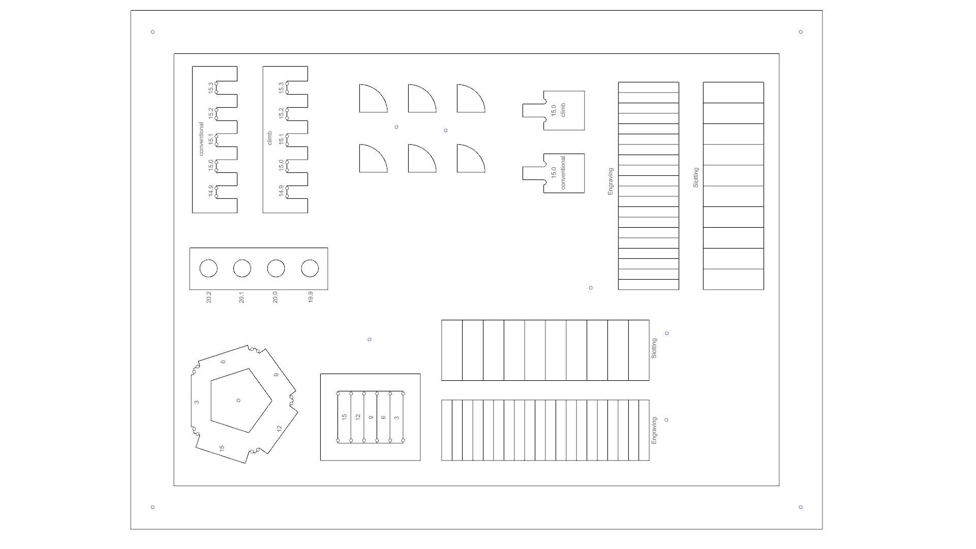
Setting Files on the Board Area
The first step was defining the material size and creating a rectangle matching the full shape of my board, along with points for screw placement.
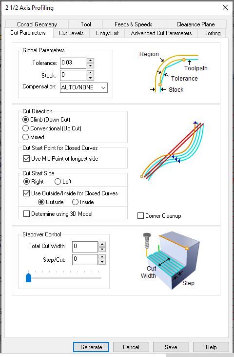
Settings for the Cut
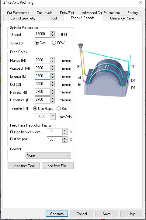
We used a ∅6 mm Down cut Flat end mill. The formula for calculating the tool’s feed and speed was:
Feed rate = N x CPT x RPM
- N: Number of flutes
- CPT: Chip load
- RPM: Spindle rotational speed
Parameters used:

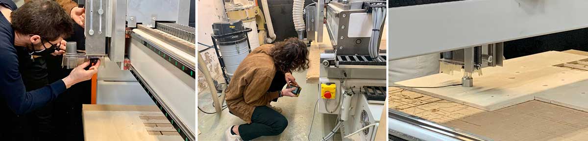
Steps to Set the Machine
- Position 0: Default at the bottom left corner; the X-axis is along the longest side of the machine.
- Tool Changes: Remove the dust collector for easier tool changes. Use the machine’s wrench and key to release the collet and holder.
- Board Setup: Avoid using the worn right corner of the bed; set the origin for X and Y appropriately. For the Z-axis, use the auto-leveler placed under the tool.
Safety Considerations
- Ensure the dust collector is on.
- Know the location of emergency buttons.
- Wear safety glasses, closed shoes, and earmuffs.
- Do not approach the machine or touch it while it is operating.
Issues encountered included weak bridges causing pieces to pop out due to board warping. We adjusted the bridges to ensure a proper cut.
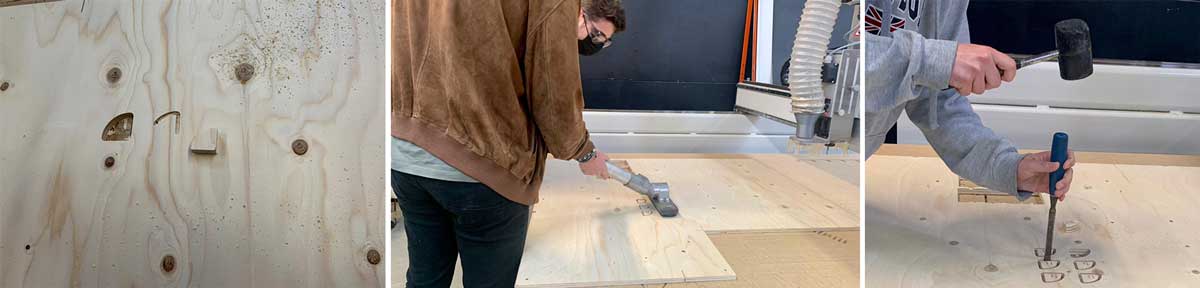
Finishing a Job
- Move the axis away to access cutout pieces.
- Turn off the machine and dust collector.
- Remove the material, using a stake and mallet if necessary.
- Clean parts with a vacuum cleaner for easier removal.
- Vacuum the area, put away the board and protective gear, and leave everything in its original state.
Speed Test
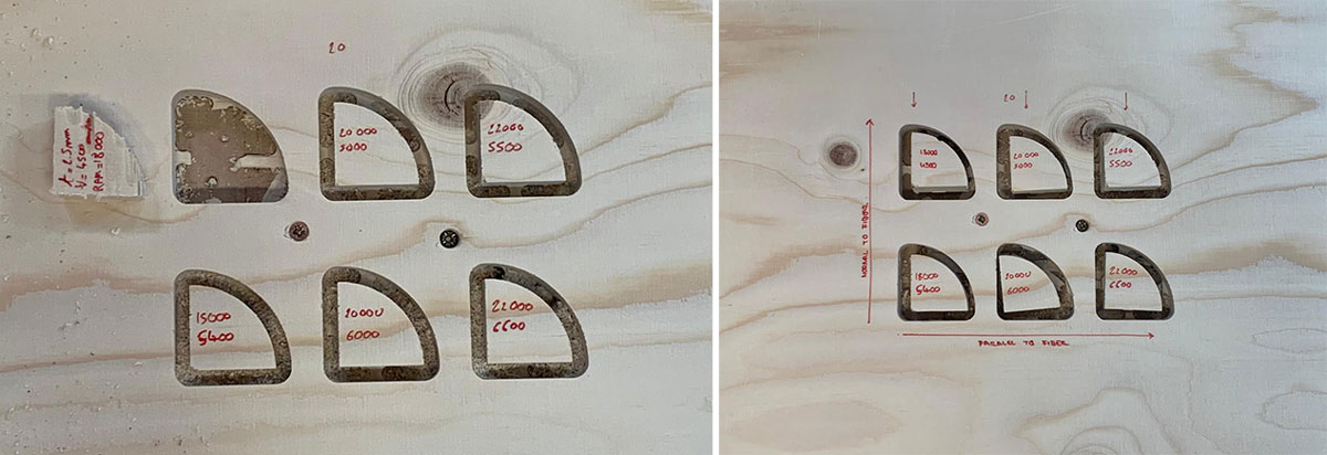
The RPM/Feed Rate test showed better results at lower speeds. We decided on a speed of 5,000mm/min at 20,000rpm, though instructors recommended a setting of 18,000rpm at 5,400mm/min.
Kerf Test
The final test included:
- Thickness of cut for fit.
- Radius for fitting a wooden rod.
- Tab ladder fit with different lengths.
- Flexible surface with plywood.
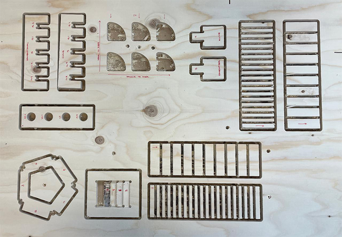
Make Something Human Scale Size
For this part of the assignment, I chose to make a stool that can also be used as a small table. The design aimed to be simple, versatile, portable, and easy to disassemble for transport.
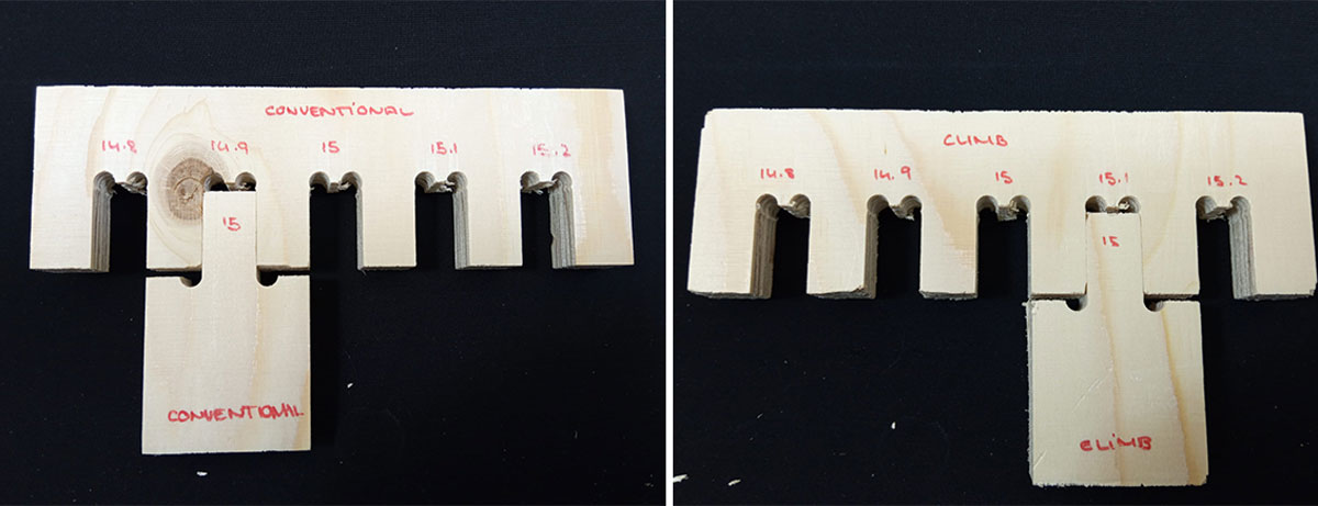
I used Rhino to design the stool and created a 3D model to ensure all parts fit together. The stool features rounded legs for a chubby appearance and a large handle. I checked the fit of all pieces with two different tolerances: a tight joint for the legs and a looser joint for the top part due to potential imperfections in the cut. The wood used was soft and easily compressed.

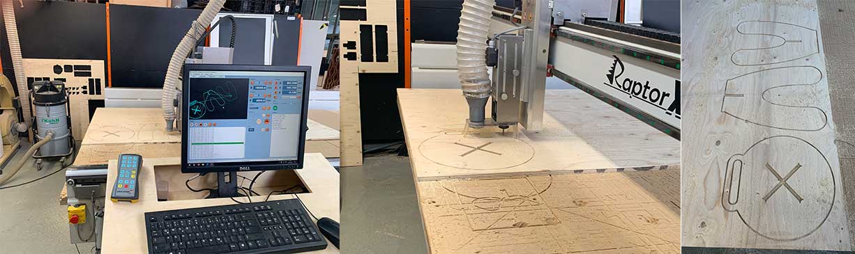
CNC - Machining
After Finishing the Design
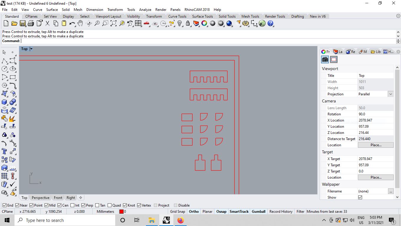
After finishing my design, I uploaded it to the cloud and reopened it from the lab’s computer, where I accessed RhinoCAM. I had forgotten some settings needed for a proper cut file, so I required a lot of help from Josep. To ensure I wouldn’t face the same issue in the future, I decided to document all the settings.
Board Preparation
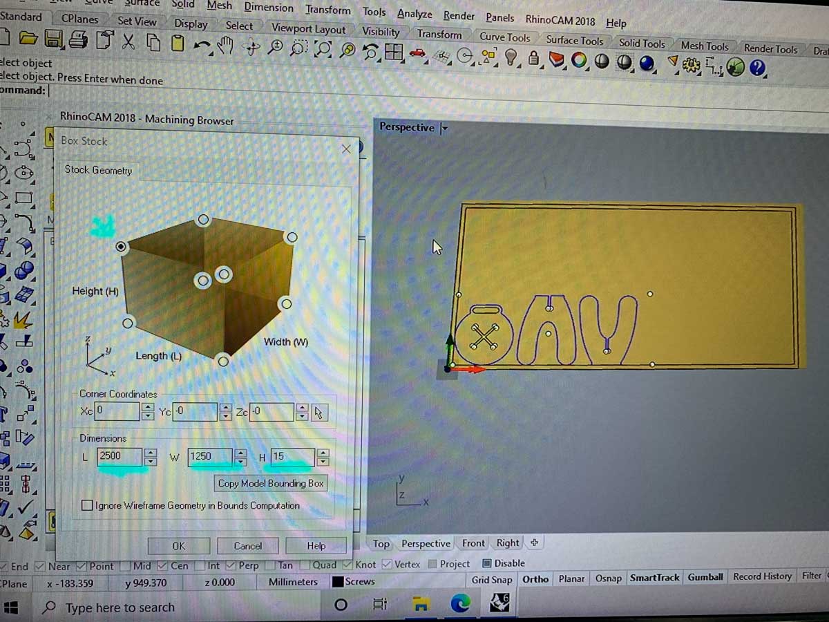
First, I measured the board to account for any thickness variations. In my case, there was a 1mm difference across the board. My stool design was small, so I fit it on one side of the board.
- Board Size: 2500 x 1250 mm
I went back to the computer, created a board in RhinoCAM, set its size, selected the top point, and created a rectangle with a 30mm offset where I would place the screws.
The distance between two parts must be greater than twice the tool diameter.
Tool Settings
I used a 6mm Flat end-mill with the following parameters:
- Holder Diameter: 30mm
- Holder Length: 45mm
- Shank Diameter: 6mm
- Tool Length: 35mm
- Shoulder Length: 27mm
- Flute Length: 27mm
-
Tool Diameter: 6mm
-
Speed: 18,000 rpm
- Direction: CW
- Plunge, Approach & Engage: 2250
- Cut: 4500
- Retract & Departure: 2250
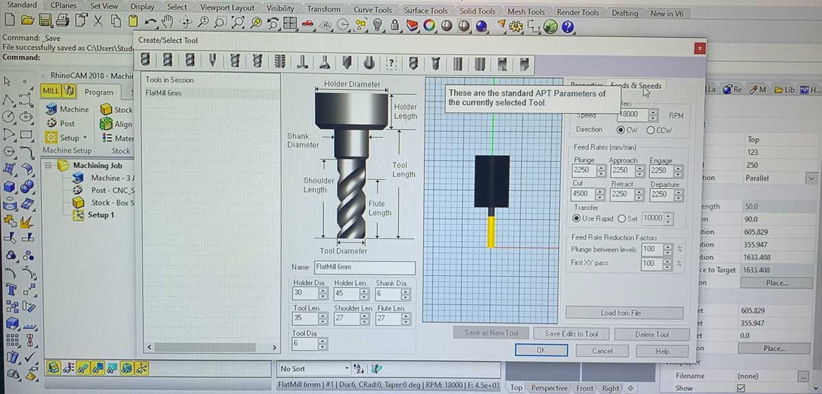
I took screenshots of all the settings for future reference, as I knew I wouldn’t remember them all.
To define the tool, I used the best test parameters from the group assignment. Josep recommended using 18,000 rpm for the speed.
To determine the correct milling parameters, we used the following equation:
chip load = SPEED (mm/min) / (RPM * Flute number)
From the chip load, RPM, and Flute number, we calculated the speed:
SPEED [mm/min] = chip load * RPM * Flute number
Screw Settings
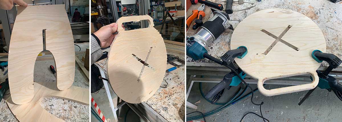
My board was slightly bent, and my stool was small, so I knew I needed additional screws. During our class demonstration, we learned that additional screws require creating a file to avoid milling over them. I used the same settings as for the test and took pictures while defining the settings, which I reviewed with Josep. This step secures the wood and ensures a safer process.
For this procedure, I needed to engrave points for the screws using the same tool as for the rest of the cut.
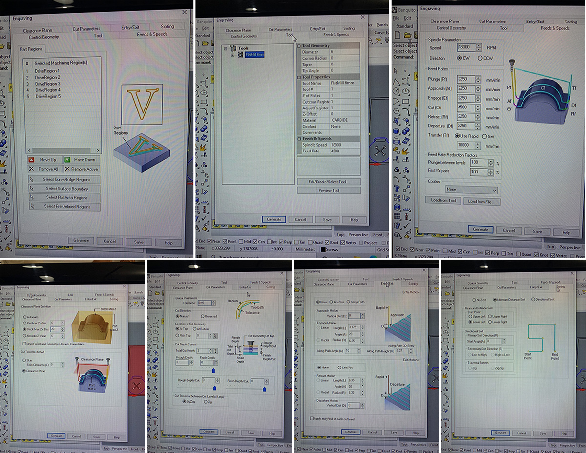
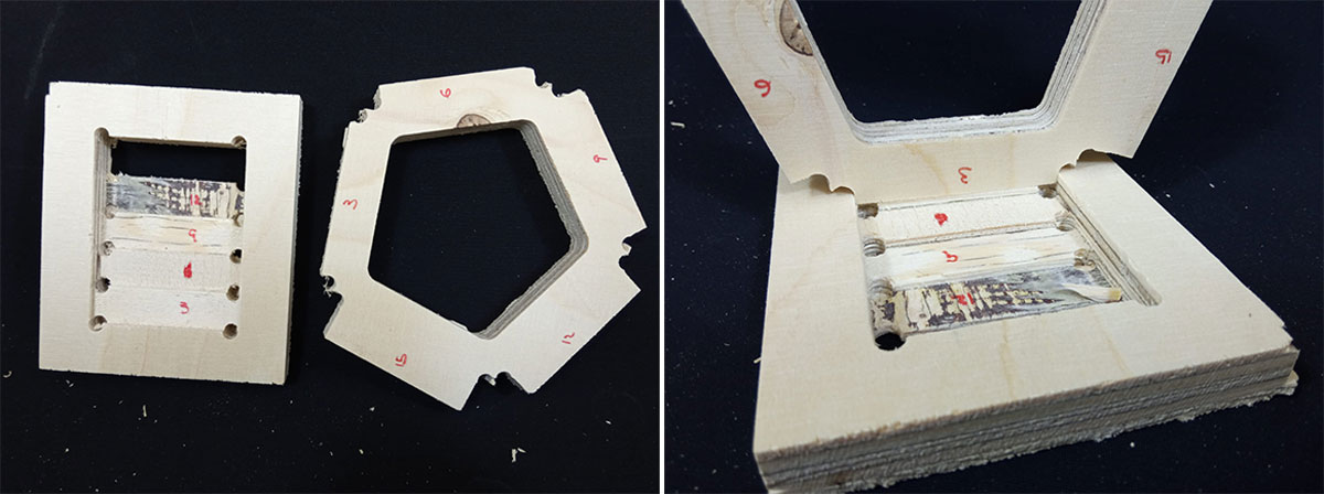
Joint Holes Settings
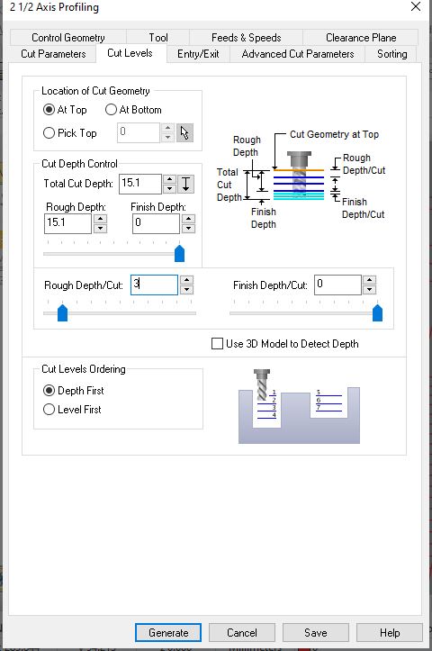
For creating joint holes, we used controlled hole cuts. The file is similar to the screws file but creates holes instead of engraving. I increased the total cut depth from 3mm to 15.2mm and lowered the Rough Depth parameter to 1/5 of the total depth for a gradual cut. This method proved to be very accurate, and everything fit perfectly.
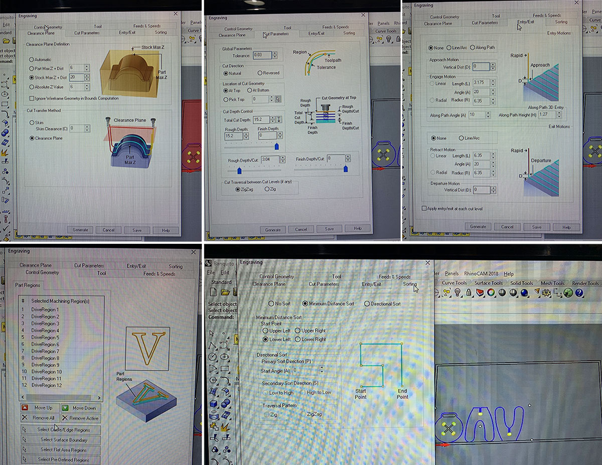
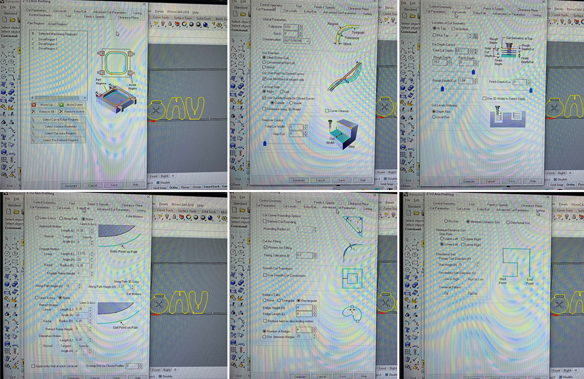
Pocket Settings
To create pockets for the wood joints, I used specific settings to ensure visibility and accuracy. I had to be very precise with tolerances.
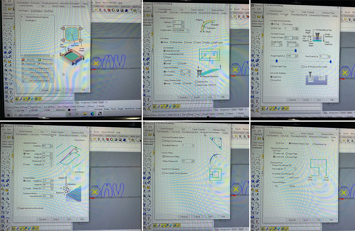
Internal Cut Settings
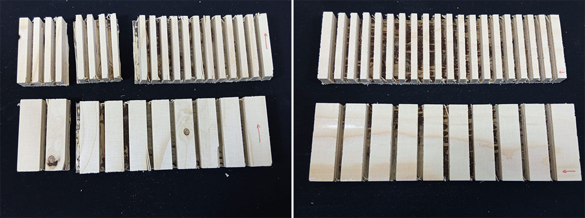
For the internal cut (the handle), I carefully set the number and size of the bridges to avoid excessive cutting or premature piece detachment. I set the bridges to 3, rectangular, with 4mm height and length.
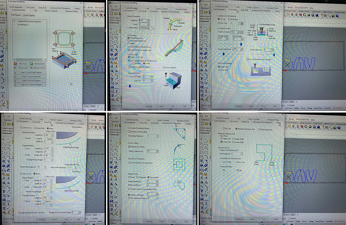
Exterior Cut Settings
For the exterior cuts, I used almost the same parameters as for the internal cuts but added one more bridge. I changed the option for Closed Curves from Inside to Outside.
File Ready to Cut
I first ran the file to set the screw points, then secured the screws on the machine bed to prevent the board from moving during cutting.
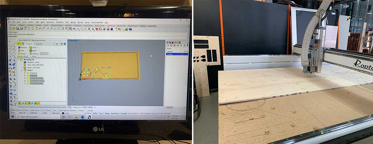
The Cut
While the machine was cutting the pieces, I monitored the process. There was a minor issue due to the board being slightly warped.
Sanding
The top piece was not perfectly cut and had a thin wood sheet on the surface. I used four sanding processes to address this:
- Manual: Sanding papers 80, 120, and 360.
- Power Tool: For borders, legs, and X shape.
- Dremel: For T-bones holes.
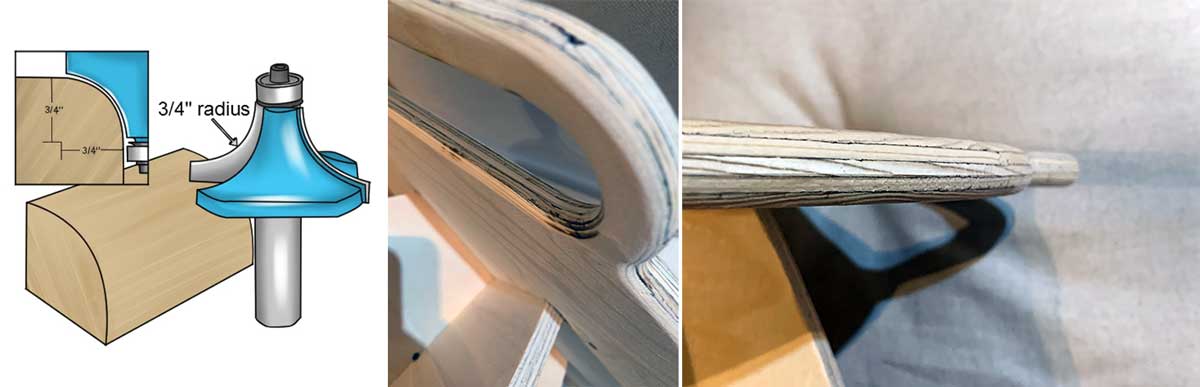
- Electric Wood Router: To round the edges of the top piece and grip.
The bullnose router bit creates a perfectly shaped half-round profile.
Additional Tools Needed:
- Wood jaws
- Sandpaper
Ensure you wear safety goggles to protect your eyes from wood trimmings. I didn’t practice beforehand and ended up burning the wood 😬
Secure the wood to minimize movement. Use wood jaws to avoid damage. Place the router on the tool, remove any previous blades, and fit the bullnose router bit. Secure it with a nut. When operating, press toward the wood edge and move at a constant speed to avoid burning. Smooth the edge with sandpaper after finishing.
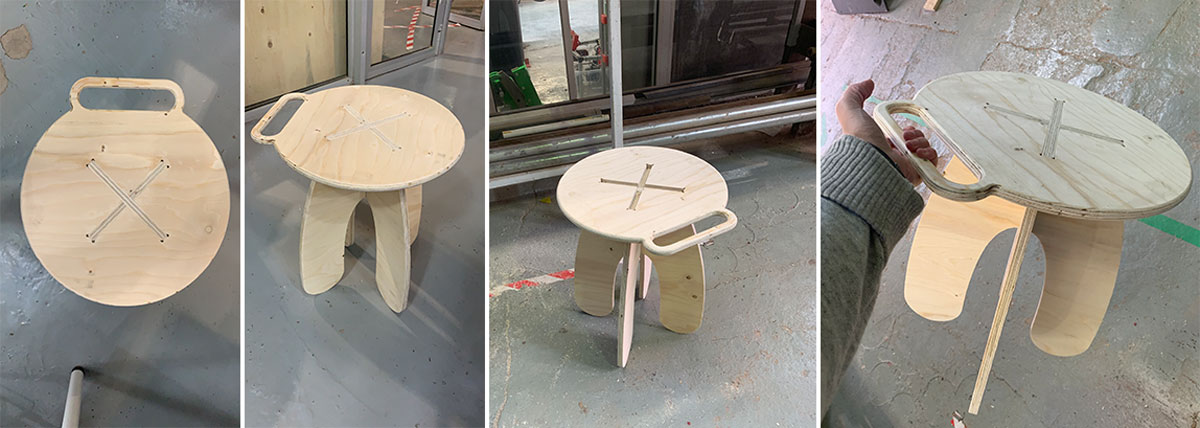
The Stool
Find All the Files Here: