13. Outputs
Week assignment
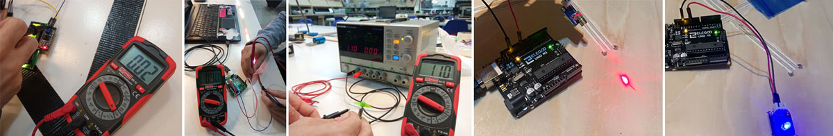
- Measuring the power consumption of an output device (in group)
- Adding an output device to my board and programming it to perform a task (individually)
Measuring Power Consumption
In our group, we measured the power consumption of various output devices and shared our findings. I chose to test a laser module and an auto-flashing LED.
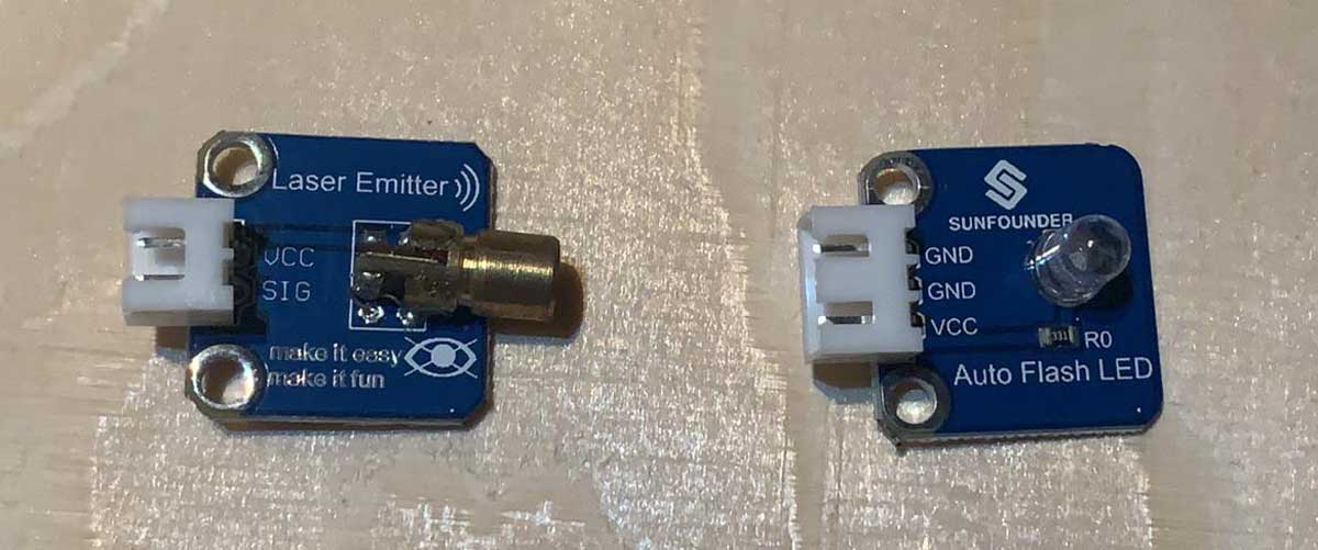
For the laser, I followed this tutorial. The project involves controlling the laser by turning it on and off at 100 millisecond intervals.
int laserPin = 10;

void setup ()
{
  pinMode(laserPin, OUTPUT);
}

void loop () {
  digitalWrite(laserPin, HIGH);
  delay(100);
  digitalWrite(laserPin, LOW);
  delay(100);
}
Measuring Power Consumption
In our group, we measured the power consumption of various output devices and shared our findings. I chose to test a laser module and an auto-flashing LED.
For the laser, I followed this tutorial. The project involves controlling the laser by turning it on and off at 100 millisecond intervals.
For the auto-flashing LED, I used this tutorial. This setup involves turning the LED on and off with 2000 millisecond intervals, causing the 7 different lights to flash simultaneously.
void setup () {
  // Initialize the digital pin as an output.
  // Pin 11 has an LED connected on most Arduino boards:
  pinMode (11, OUTPUT);
}

void loop () {
  digitalWrite (11, HIGH); // set the LED on
  delay (2000); // wait for a second
  digitalWrite (11, LOW); // set the LED off
  delay (2000); // wait for a second
}
The group also measured an LCD screen, a Small DC motor and a LED RGB (144 LEDS). I sumarized the data on this table:
| Module | Working current[mA] | Output Datasheet |
|---|---|---|
| LCD | 20 | HD44780U |
| DC motor | 1100 | DC motor 6/9V |
| LED RGB | 170-800 | SK6812 |
| Laser | 50/30 | Laser Transmitter |
| Autoflash LED | 80/40 | 7-Color Auto-flash LED |
Adding an Output Device to My Board
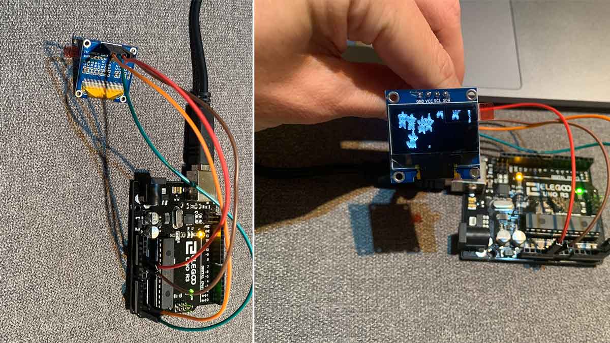
For this assignment, I continued working on my final project by integrating an OLED display into my board. I initially used the board I created during the inputs week, which had the inverted SCL and SDA pins. To test the OLED, I connected it with wires and followed the instructions.
I used Adafruit’s SSD1306 library, which is for monochrome displays, and the Adafruit GFX library for patterns, images, and text.
I attempted to use the LCD Bitmap Converter from this link but discovered it was not compatible with iOS. Instead, I used an example from the Adafruit library by following this tutorial:
- Opened the example program from File -> Examples -> Adafruit SSD1306 ->
ssd1306_128x64_i2c, since we were using an OLED display with an I2C interface and a screen size of 128x64.
However, the OLED display was not functioning. I decided to test it with an Arduino UNO to rule out the possibility that the OLED was defective. After switching the SCL and SDA pins on the Arduino to A4 and A5, respectively, the issue persisted. I then found a troubleshooting video:
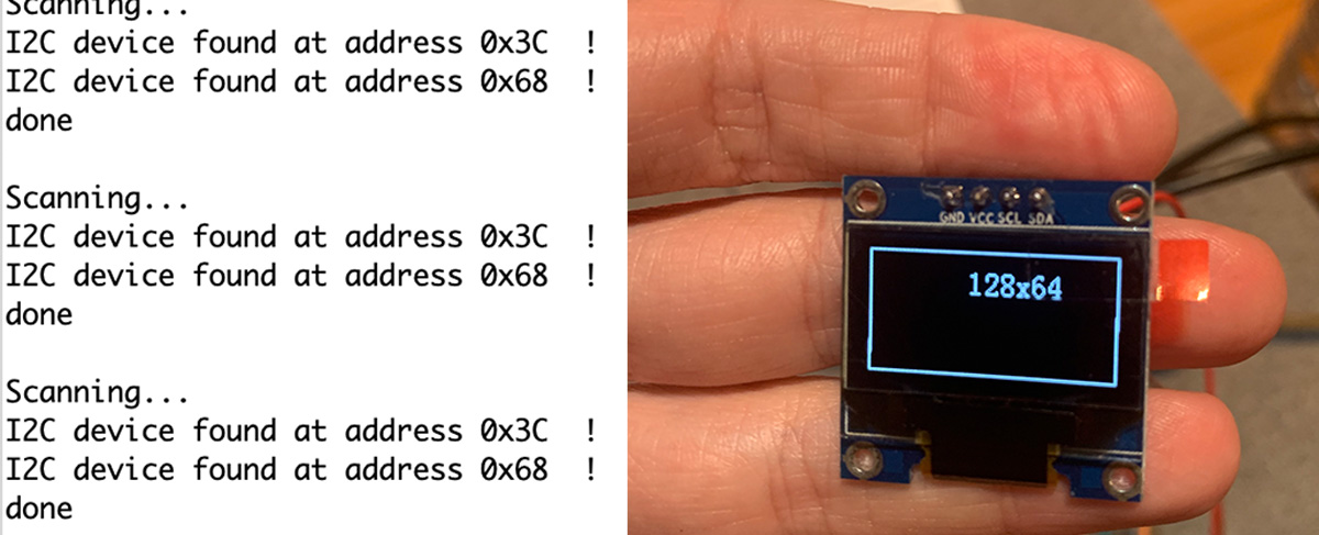
Tip: I had not checked if the OLED was 64x32 or 128x32. Changing the size in the code from ssd1306_128x64_i2c to ssd1306_128x32_i2c solved the issue temporarily. It turned out that the OLED was not actually 128x32; it was a different model with the address 0x3C instead of 0x3F. This mismatch caused the distorted image when using the 128x32 code.
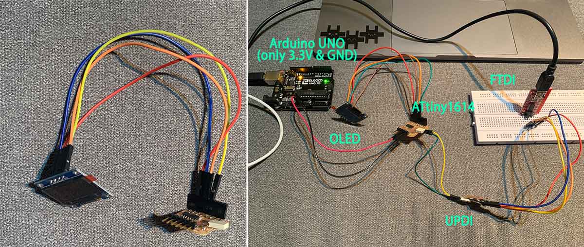
Still unsure why the OLED wasn’t working with my board, I decided to start with simpler code to better understand the process. I found this repository with a simpler approach using the Tiny4kOLED library. I installed the Tiny4kOLED library and uploaded the example code.
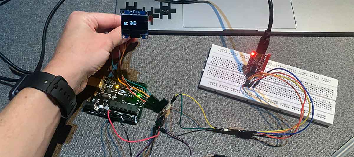
Since the OLED uses I2C communication, the wiring is straightforward: SDA, SCL, VCC, and GND. The challenge was powering the board and the OLED. I connected the board to the OLED, then to the UPDI, the UPDI to the FTDI, and the FTDI to the computer. To power both the board and OLED, I used an Arduino UNO, connecting VCC from the board to 3.3V and GND to GND.
#include <Tiny4kOLED.h>

void setup() {
  // Send the initialization sequence to the oled. This leaves the display turned off
  oled.begin();

  // Two rotations are supported,
  // The begin() method sets the rotation to 1.
  //oled.setRotation(0);

  // Two fonts are supplied with this library, FONT8X16 and FONT6X8
  // Other fonts are available from the TinyOLED-Fonts library
  oled.setFont(FONT8X16);

  // Clear the memory before turning on the display
  oled.clear();

  // Turn on the display
  oled.on();

  // Switch the half of RAM that we are writing to, to be the half that is non currently displayed
  oled.switchRenderFrame();
}

void loop() {
  updateDisplay();
  delay(50);
}

void updateDisplay() {
  // Clear the half of memory not currently being displayed.
  oled.clear();

  // Position the text cursor
  // In order to keep the library size small, text can only be positioned
  // with the top of the font aligned with one of the four 8 bit high RAM pages.
  // The Y value therefore can only have the value 0, 1, 2, or 3.
  // usage: oled.setCursor(X IN PIXELS, Y IN ROWS OF 8 PIXELS STARTING WITH 0);
  oled.setCursor(0, 1);

  // Write text to oled RAM (which is not currently being displayed).
  oled.print(F("ms: "));

  // Write the number of milliseconds since power on.
  oled.print(millis());

  // Swap which half of RAM is being written to, and which half is being displayed.
  // This is equivalent to calling both switchRenderFrame and switchDisplayFrame.
  oled.switchFrame();
}
This code worked, so I suspected there might be an issue with the previous code or the ATtiny1614 I was using. The error message I encountered when trying to upload the Adafruit code was:
Error compiling for board ATtiny1614/1604/814/804/414/404/214/204.
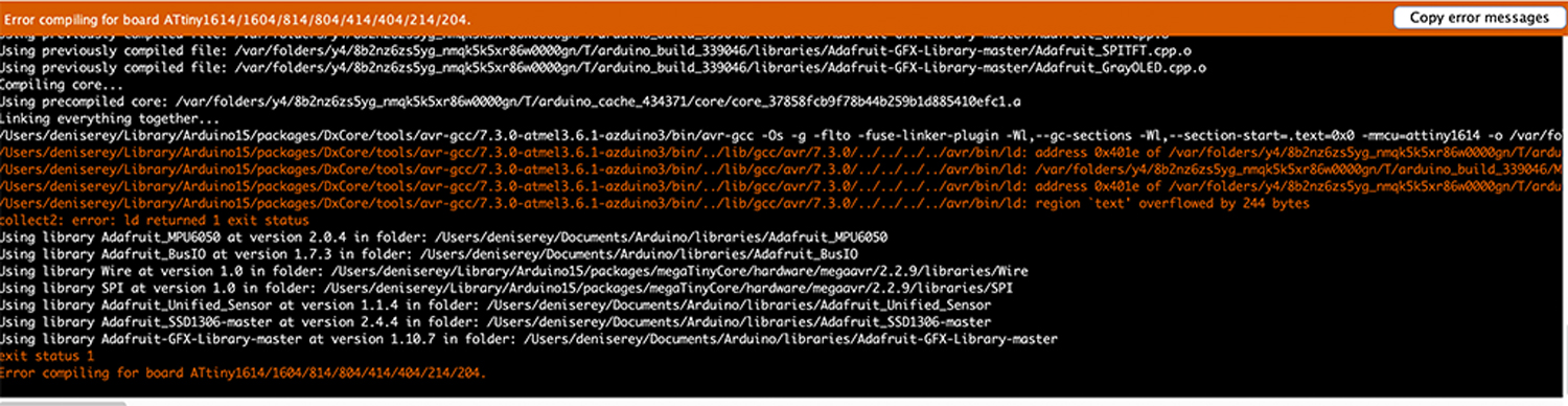
After a lot of time and frustration trying to identify the issue, I noticed that successful compilations showed the percentage of memory used:

The ATtiny1614 has 16k of memory. Edu had mentioned potential memory issues with complex graphics, but I wasn’t expecting a ‘not enough space’ error. The error I encountered was not informative.
I began commenting out sections of the Adafruit code, including the loop and setup, to isolate the problem. It became clear that the issue was with the libraries—the Adafruit libraries for the OLED were too large for the ATtiny1614.
This was definitely the most frustrating week so far. Since my goal was to run the MPU6050 with the OLED, I decided to switch to the Tiny4kOLED library and integrate the gyroscope code to display gyroscope data on the screen.
MPU6050 & OLED I2C
I used a 128x64 I2C OLED module. I2C is a serial communication protocol where data is transferred bit by bit along a single wire (the SDA line). The MPU6050 uses the same protocol.
To determine the addresses for both modules, I used this tutorial to check the address:
Using the Gyroscope on the MPU6050
The gyroscope can detect orientations. For my final project, I planned to use it to interact with the game. The accelerometer will track user movement when not playing the game. The MPU6050 sensor can detect three axes:
- X-axis = Pitch
- Y-axis = Roll
- Z-axis = Yaw
For this test, I aimed to understand the gyroscope’s functionality and display its data on the OLED screen. Both the OLED and the MPU6050 are I2C modules, which means I need only four wires to interface them with the board: GND, VCC, SCL, and SDA.
The gyroscope is complex, especially for me. To simplify it, I focused on understanding its basic functionality. The gyroscope operates using a vibrating structure to measure the rate of rotation, known as a MEMS (Micro Electro Mechanical Systems) angular rate sensor. This sensor measures angular rotation.
To get a better grasp, I read this friendly explanation.
I also found the MPU6050_light library, which simplifies the calculations needed to interpret the sensor’s data. Following this tutorial, I used the following code:
/* Get tilt angles on X and Y, and rotation angle on Z
    Angles are given in degrees
 License: MIT
 */
 #include "Wire.h"
 #include <MPU6050_light.h>
 MPU6050 mpu(Wire);
 unsigned long timer = 0;
 void setup() {
   Serial.begin(9600);
   Wire.begin();
 byte status = mpu.begin();
   Serial.print(F("MPU6050 status: "));
   Serial.println(status);
   while (status != 0) { } // stop everything if could not connect to MPU6050
 Serial.println(F("Calculating offsets, do not move MPU6050"));
   delay(1000);
   mpu.calcOffsets(); // gyro and accelero
   Serial.println("Done!\n");
 }
 void loop() {
   mpu.update();
 if ((millis() - timer) > 10) { // print data every 10ms
     Serial.print("X : ");
     Serial.print(mpu.getAngleX());
     Serial.print("\tY : ");
     Serial.print(mpu.getAngleY());
     Serial.print("\tZ : ");
     Serial.println(mpu.getAngleZ());
     timer = millis();
   }
 }
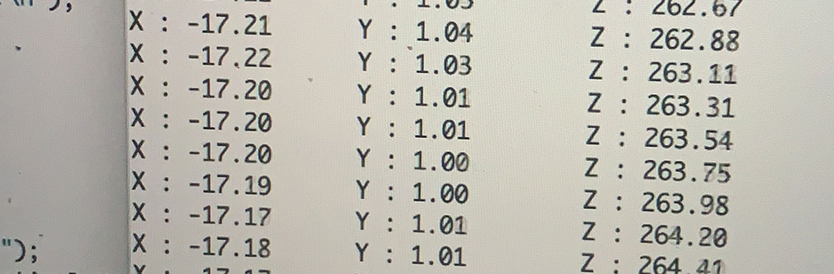
!!!! note I discovered that there is an auto-calibration feature that activates when flashing the board. I need to investigate this further for my final project, as it may impact the performance of my device.
When turning the sensor to the left, the numbers decreased, and when turning it to the right, they increased. The next step was to integrate parts of the gyroscope code with the OLED code.
For the initial test, I copied the gyroscope code into the OLED code, resulting in the following:
While the gyroscope data was being displayed on the serial monitor, the OLED was showing unrelated data. My goal for the final project is to use the Y-axis position of the gyroscope to control a digital character. To achieve this, I needed to experiment with merging the two codes so that the gyroscope data could be properly displayed on the OLED.
Given my previous struggles with getting the ATtiny to work with the OLED, this task seemed relatively straightforward. I began by copying and pasting code from one sketch to another until I achieved a working integration.
// Choose your I2C implementation before including Tiny4kOLED.h

#include <Tiny4kOLED.h>
#include <Wire.h>
#include <MPU6050_light.h>

MPU6050 mpu(Wire);

void setup() {
  // Send the initialization sequence to the oled. This leaves the display turned off
  oled.begin();

  // Two fonts are supplied with this library, FONT8X16 and FONT6X8
  // Other fonts are available from the TinyOLED-Fonts library
  oled.setFont(FONT8X16);

  // Clear the memory before turning on the display
  oled.clear();

  // Turn on the display
  oled.on();

  // Switch the half of RAM that we are writing to, to be the half that is non currently displayed
  oled.switchRenderFrame();

  Serial.begin(9600);
   Wire.begin();
 byte status = mpu.begin();
   Serial.print(F("MPU6050 status: "));
   Serial.println(status);
   while (status != 0) { } // stop everything if could not connect to MPU6050
 Serial.println(F("Calculating offsets, do not move MPU6050"));
   delay(1000);
   mpu.calcOffsets(); // gyro and accelero
   Serial.println("Done!\n");
}

void loop() {

  mpu.update();

     Serial.print("X : ");
     Serial.print(mpu.getAngleX());
     Serial.print("\tY : ");
//   Serial.print();
     Serial.print("\tZ : ");
     Serial.println(mpu.getAngleZ());

  delay(50);
  updateDisplay(mpu.getAngleY());
}

void updateDisplay(float angleY) {
  // Clear the half of memory not currently being displayed.
  oled.clear();

  // Position the text cursor
  // In order to keep the library size small, text can only be positioned
  // with the top of the font aligned with one of the four 8 bit high RAM pages.
  // The Y value therefore can only have the value 0, 1, 2, or 3.
  // usage: oled.setCursor(X IN PIXELS, Y IN ROWS OF 8 PIXELS STARTING WITH 0);
  oled.setCursor(0, 1);

  // Write text to oled RAM (which is not currently being displayed).
  oled.print(F("ms: "));

  // Write the number of milliseconds since power on.
  oled.print(mpu.getAngleY());

  // Swap which half of RAM is being written to, and which half is being displayed.
  // This is equivalent to calling both switchRenderFrame and switchDisplayFrame.
  oled.switchFrame();
}
Explanation of the code
I used the following libraries. To Tiny4kOLED I added Wire, MPU6050_light
#include <Tiny4kOLED.h>
#include <Wire.h>
#include <MPU6050_light.h>
As both modules uses Wire.h I had to declare that it was only for the accelerometer (this is probably not the technical way to say this). I added this:
MPU6050 mpu(Wire);
This runs all for the OLED first. The OLED is inicialliced with oled.begin.
  // Send the initialization sequence to the oled. This leaves the display turned off
  oled.begin();

  // Two fonts are supplied with this library, FONT8X16 and FONT6X8
  // Other fonts are available from the TinyOLED-Fonts library
  oled.setFont(FONT8X16);

  // Clear the memory before turning on the display
  oled.clear();

  // Turn on the display
  oled.on();

  // Switch the half of RAM that we are writing to, to be the half that is non currently displayed
  oled.switchRenderFrame();

  ```

Only then, the MPU6050 is iniciallized. The MPU6050 is inicialliced with Wire.begin.
Then, I defined the data that I wanted from the MPU6050. I just wanted to show the data in Y.
// measures the gyro data with a dealy of 50 milliseconds delay(50); // This is the only mesure that will be shown in the OLED updateDisplay(mpu.getAngleY()); ```
So, by using the function updateDisplay(mpu.getAngleY()) and the parameter float angleY saying that the number is a decimal.
// Create a function that recieves the value to display
  void updateDisplay(float angleY) {
  // Clear the half of memory not currently being displayed.
  oled.clear();

  // Position the text cursor
  // In order to keep the library size small, text can only be positioned
  // with the top of the font aligned with one of the four 8 bit high RAM pages.
  // The Y value therefore can only have the value 0, 1, 2, or 3.
  // usage: oled.setCursor(X IN PIXELS, Y IN ROWS OF 8 PIXELS STARTING WITH 0);
  oled.setCursor(0, 1);

  // Write text to oled RAM (which is not currently being displayed).
  oled.print(F("ms: "));

  // Write the number of milliseconds since power on.
  oled.print(mpu.getAngleY());

  // Swap which half of RAM is being written to, and which half is being displayed.
  // This is equivalent to calling both switchRenderFrame and switchDisplayFrame.
  oled.switchFrame();
}
Download file here: