11. Input Devices
Week Assignment
-
This week’s assignment involved adding a sensor to a microcontroller board I designed and reading its output.
-
Probe and measure the input device’s analog levels and digital signals (group work).
Sensors
Sensors acquire a physical quantity and convert it into an electrical signal suitable for processing.
- Sensors: Input is a physical quantity, and output is electrical.
- Actuators: Input is electrical, and output is a physical quantity.
Analog vs Digital Sensors
I decided to compare an analog temperature sensor with a digital temperature sensor.
Before the test, I researched the differences between analog and digital sensors and their operation here.
An analog signal can take on any value within a range, while a digital signal has only two states: HIGH and LOW. Analog sensors require an analog-to-digital converter (ADC) to read their output.
- Analog Signal: Can vary continuously (e.g., 0 to 255).
- Digital Signal: Has discrete steps, making it simpler to use.
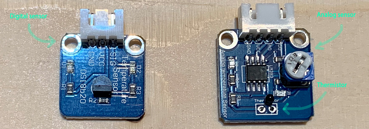
Analog Temperature Sensor
An analog temperature sensor measures temperature and converts it into an output signal. It uses an NTC (Negative Temperature Coefficient) thermistor, which decreases in resistance as temperature increases.
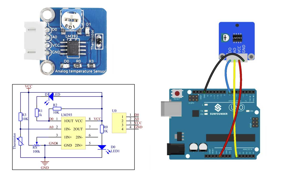
For this test, I used an Arduino UNO board with an analog temperature sensor module to observe how the value on A0 changes when I touch the sensor. I monitored these values on the serial monitor.
I uploaded the following code to the Arduino UNO and used the LiquidCrystal_l2C library, which I found here. To install the library:
- Open Arduino IDE > Sketch > Include Library > Add ZIP Library.
- Locate and select the
LiquidCrystal_l2CZIP file within the Sensor Kit V2.0 for Arduino. - Click “Open,” and you should see the message “Library added to your libraries.”
- Confirm the library appears under Tools > Include Library.
I then copied the provided code into the Arduino IDE, selected the appropriate board and port, verified the setup, and clicked upload.
//Analog Temperature Sensor
const int digitalPin = 7;     // Analog Temperature Sensor pin D0 to pin7
int analogPin = A0;           // Analog Temperature Sensor pin A0 to pin A0
const int ledPin =  13;      // pin 13 built-in LED light

// variables will change:
boolean Dstate = 0;          // variable for reading status of D0
int Astate = 0;            // variable for reading status of A0
void setup()
{
  pinMode(ledPin, OUTPUT); // initialize the LED pin as an output:
  pinMode(digitalPin, INPUT);  // initialize Analog Temperature Sensor D0 pin as an input
  Serial.begin(9600); // initialize serial communications at 9600 bps

}

void loop()
{
  Astate = analogRead(analogPin);  // read Analog Temperature Sensor A0 value (set point)
  Dstate = digitalRead(digitalPin);  // read state of Analog Temperature Sensor D0
  Serial.print("D0: ");
  Serial.println(Dstate);//print the value of D0
  Serial.print("A0:");
  Serial.println(Astate);//print the value of A0
  // check if the pushbutton is pressed.
  // if it is, the buttonState is HIGH:
  if (Dstate == HIGH)    // check if Analog Temperature Sensor D0 is HIGH
  {
    // turn LED on:
    digitalWrite(ledPin, LOW);
  }
  else
  {
    // turn LED off:
    digitalWrite(ledPin, HIGH);
  }
  delay(1000);                // controls speed of Analog Temperature Sensor and Serial Monitor display rate
}
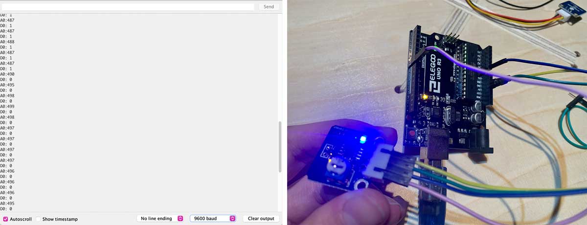
- When touching the sensor, indicating an increase in temperature, the value on A0 decreases, and D0 changes from 0 to 1. The LED on pin 13 also turns off.
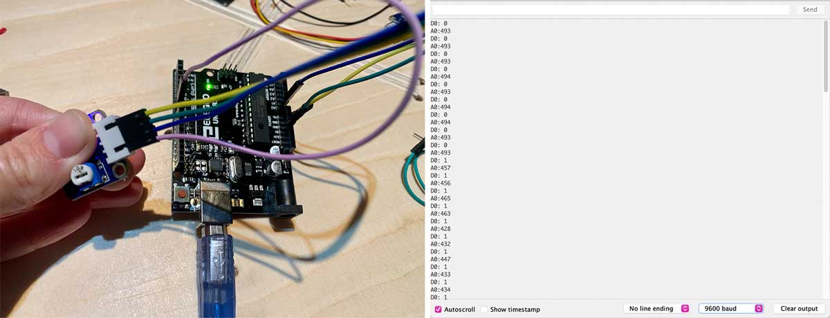
- When releasing the sensor, meaning the temperature decreases, the value on A0 increases, and D0 changes from 1 to 0 again, causing the LED on pin 13 to turn on.
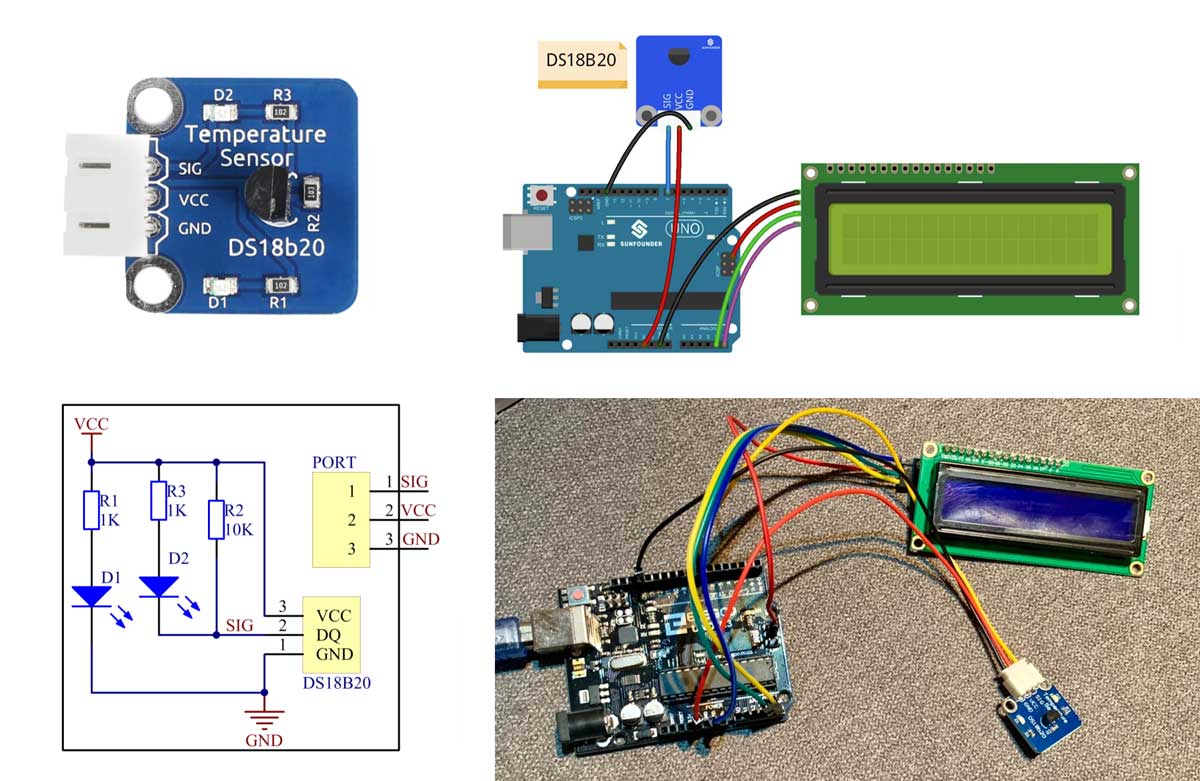
Digital Temperature Sensor
The DS18B20 digital temperature sensor requires only one pin for two-way communication with the microprocessor.
I used the following code and added the necessary libraries, following the same installation steps as for the analog sensor.
/****************************************************
name:Digital Temperature Sensor-ds18b20
function:you can see the value of current temperature displayed on the LCD.
****************************************************/
//Email:support@sunfounder.com
//website:www.sunfounder.com

/****************************************/
#include <OneWire.h>
#include <DallasTemperature.h>
#include <LiquidCrystal_I2C.h>
#include <Wire.h>
LiquidCrystal_I2C lcd(0x27,16,2);  // set the LCD address to 0x27 for a 16 chars and 2 line display
#define ONE_WIRE_BUS 7 //ds18b20 module attach to pin7
// Setup a oneWire instance to communicate with any OneWire devices (not just Maxim/Dallas temperature ICs)
OneWire oneWire(ONE_WIRE_BUS);
// Pass our oneWire reference to Dallas Temperature.
DallasTemperature sensors(&oneWire);

void setup(void)
{

  // start serial port
  Serial.begin(9600);
  sensors.begin(); // initialize the bus
  lcd.init(); //initialize the lcd
  lcd.backlight(); //turn on the backlight
}
void loop(void)
{
  // call sensors.requestTemperatures() to issue a global temperature
  // request to all devices on the bus
  Serial.print("Requesting temperatures...");
  sensors.requestTemperatures(); // Send the command to get temperatures
  lcd.setCursor(0, 0);
  lcd.print("TemC: "); //print "Tem: " on lcd1602
  lcd.print(sensors.getTempCByIndex(0));//print the temperature on lcd1602
  Serial.print("Tem: ");
  Serial.print(sensors.getTempCByIndex(0));
  Serial.println(" C");
  lcd.print(char(223));//print the unit" ℃ "
  lcd.print("C");
  lcd.setCursor(0, 1);
  lcd.print("TemF: ");
  lcd.print(1.8*sensors.getTempCByIndex(0) + 32.0);//print the temperature on lcd1602
  lcd.print(char(223));//print the unit" ℉ "
  lcd.print(" F");
  //Serial.print("Tem: ");
  //Serial.print(1.8*sensors.getTempCByIndex(0) + 32.0);
  //Serial.println(" F");
  //Serial.println("");
  //Serial.print("Temperature for the device 1 (index 0) is: ");
  //Serial.println(sensors.getTempCByIndex(0));  //print the temperature on serial monitor
}
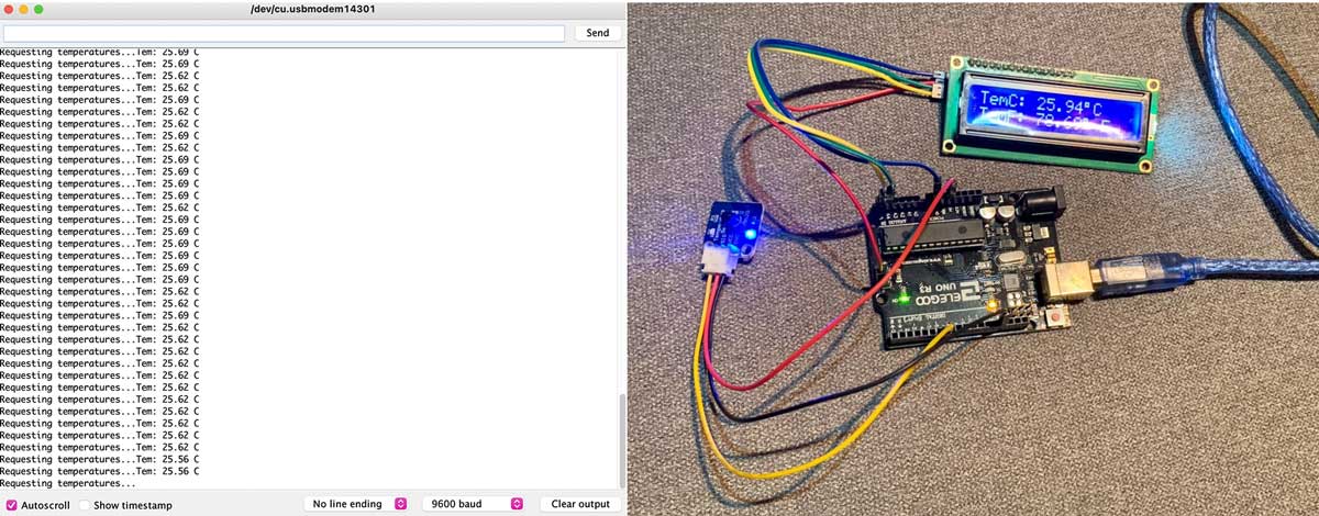
- When touching the sensor, the temperature increases. This is much simpler than the analog sensor output.
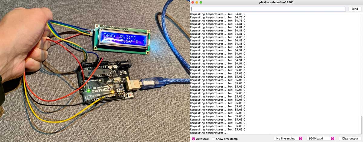
- When releasing the sensor, the temperature decreases.
Probe an Input Device’s Analog and Digital Signals
Digital Temperature Sensor
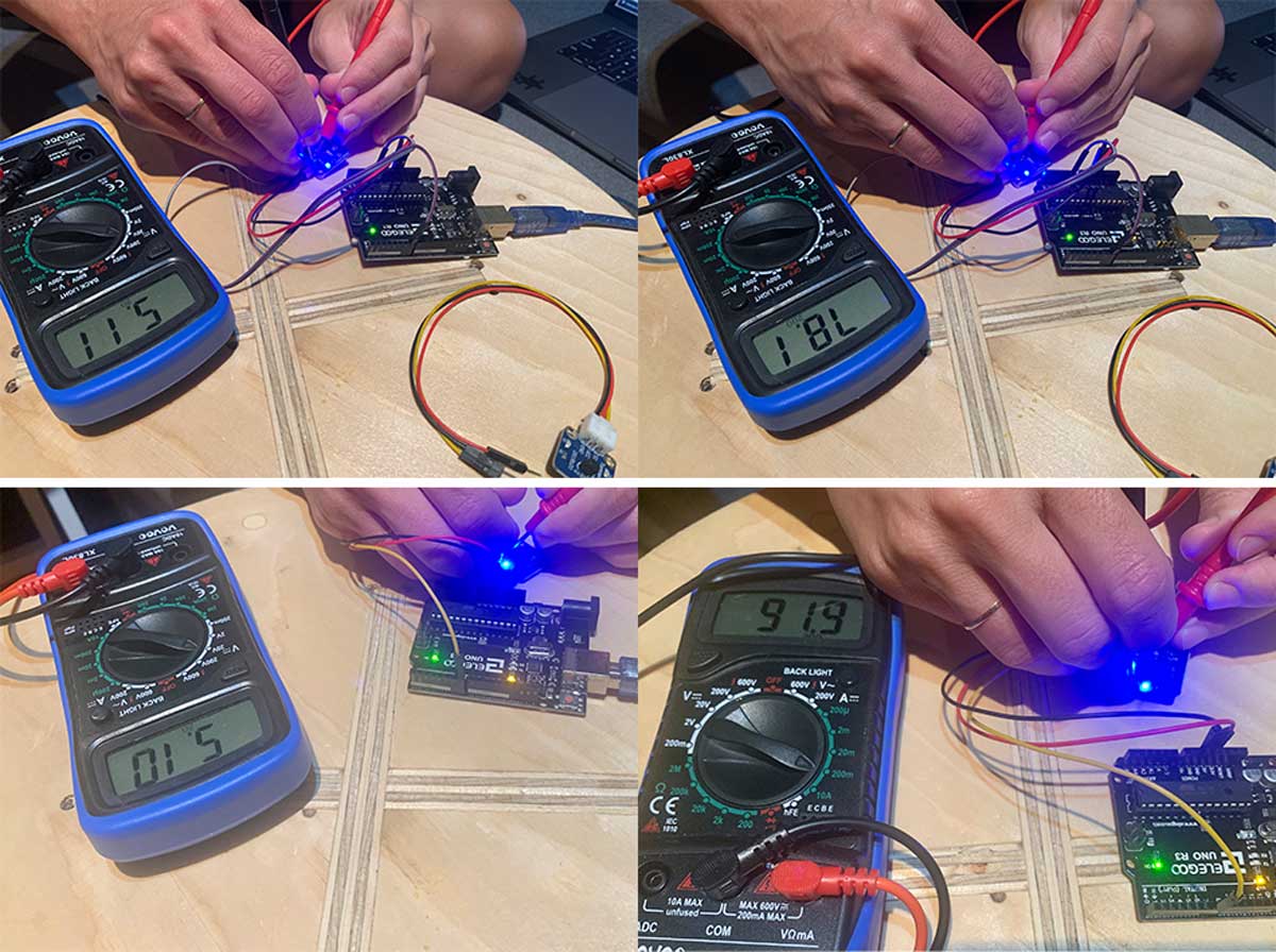
The DS18B20 is a 1-Wire digital temperature sensor from Maxim IC. It reports degrees in Celsius with 9 to 12-bit precision, ranging from -55 to 125°C (±0.5°C). Each sensor has a unique 64-bit serial number etched into it, allowing for a large number of sensors to be used on a single data bus.
- Working Voltage: 3V–5.5V
I connected the sensor to an Arduino UNO and measured the following: - Voltage: 5.11V - Current: 78.1 mA
Analog Temperature Sensor
An analog temperature sensor module typically includes an NTC thermistor, resistor, and capacitor. The NTC thermistor’s resistance decreases with increasing temperature, making it widely used for temperature detection. The temperature threshold can be adjusted using a potentiometer. When the temperature exceeds the threshold, the D0 pin outputs low, and the corresponding LED lights up.
- Working Voltage: 3.3V–5V
I connected the sensor to an Arduino UNO and measured the following: - Voltage: 5.10V - Current: 91.9 mA
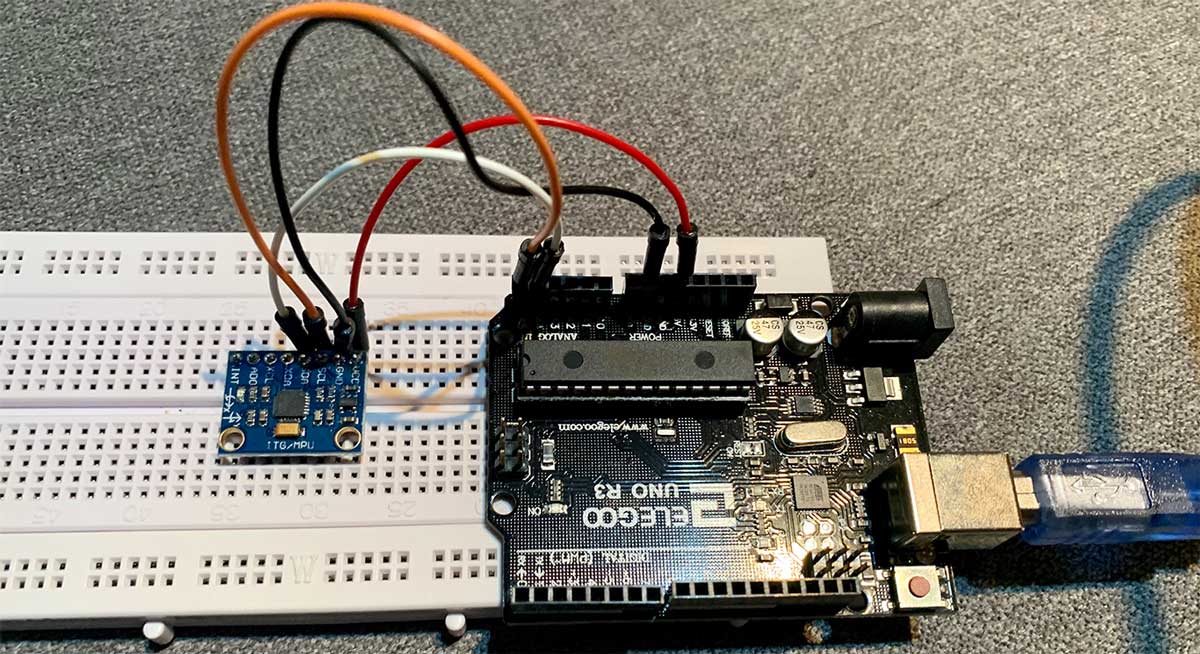
Accelerometer
The MPU6050 IMU integrates a 3-axis accelerometer and a 3-axis gyroscope on a single chip. This combination is frequently referred to as an IMU (Inertial Measurement Unit). It has 6 outputs: 3 from the accelerometer and 3 from the gyroscope.
- Accelerometer: Measures gravitational acceleration along 3 axes, allowing calculation of the sensor’s angle using trigonometric math.
- Gyroscope: Measures the rate of change of angular position over time along the X, Y, and Z axes. The outputs are in degrees per second, and the angle can be determined by integrating the velocity.
I followed this page to experiment with the accelerometer.
Connection to Arduino
For this test, I used the I2C protocol for communication with the Arduino, requiring only two wires for data communication, plus two additional wires for power.
I reviewed the Data sheet of the sensor and read about how the accelerometer works.
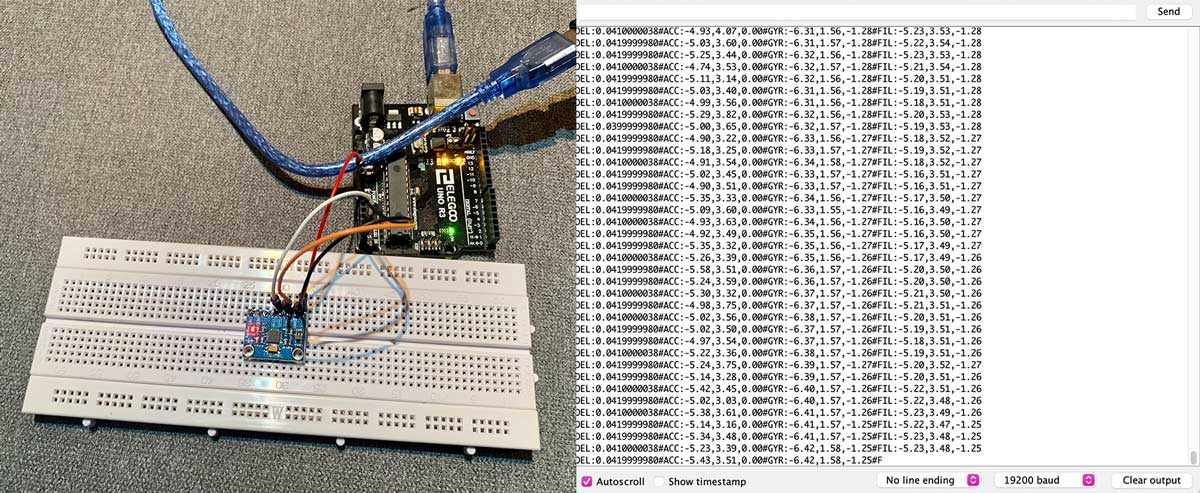
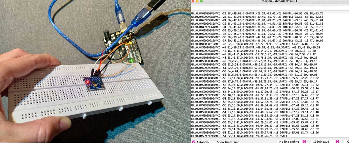
I uploaded this code to the Arduino to test the accelerometer. You can find the code here, which I sourced from the MPU-6050 Accelerometer + Gyro section of the Arduino Playground website.
The Board
First Attempt
After conducting some research and consulting with instructors, I decided to use the 6-axis accelerometer + gyroscope board on the FabAcademy inputs week site as an example. Instead of using the LSM6DS33 sensor, I opted for the MPU-6050 sensor.
I started creating my schematic using KiCad, following the documentation from week 07. Everything appeared to be correct, so I saved my file as an .svg, imported it into Inkscape, and created the interior and traces .png files. I then used ModsProject to generate files for the milling machine. However, I did not double-check if the pin positions matched the sensor’s pins. They did not align correctly, and I only realized this after soldering the board and attaching the sensor.
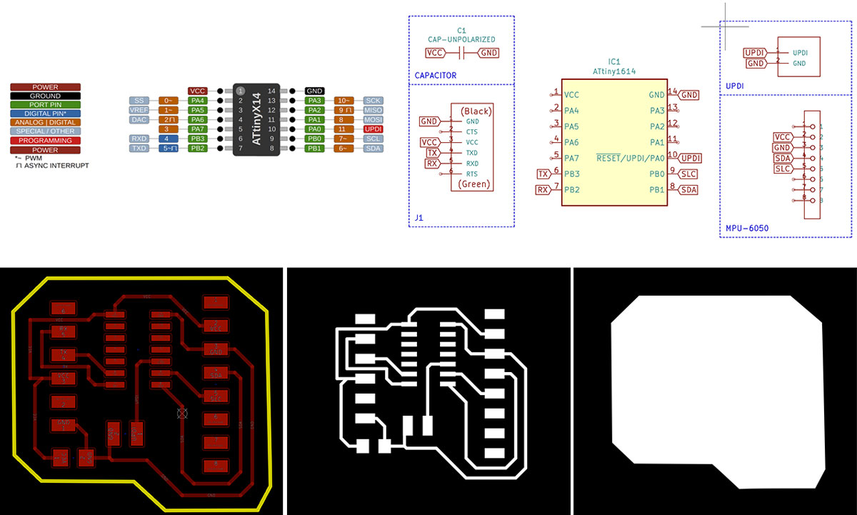
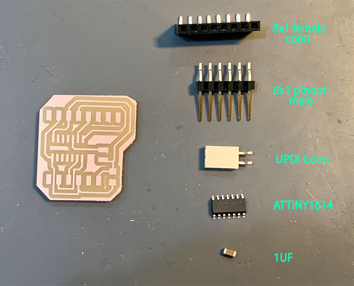
Board components
| Components | Description | Quantity |
|---|---|---|
| ATTINY1614 | 8-bit tinyAVR® 1-Series Microcontroller | 1 |
| UPDI connector | Female connector pinout UPDI | 1 |
| 1UF | Multilayer Ceramic Capacitors MLCC - SMD/SMT 50V 0.1uF | 1 |
| Male pin h | 1x6 Male Pin Header | 1 |
| MPU-6050 | MEMS accelerometer and a MEMS gyro in a single chip | 1 |
Find the fail-files here:
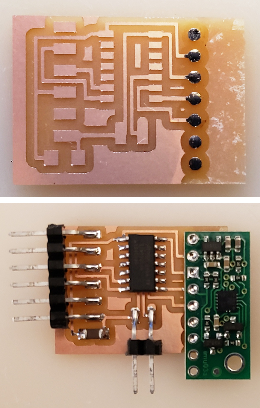
### Final Board
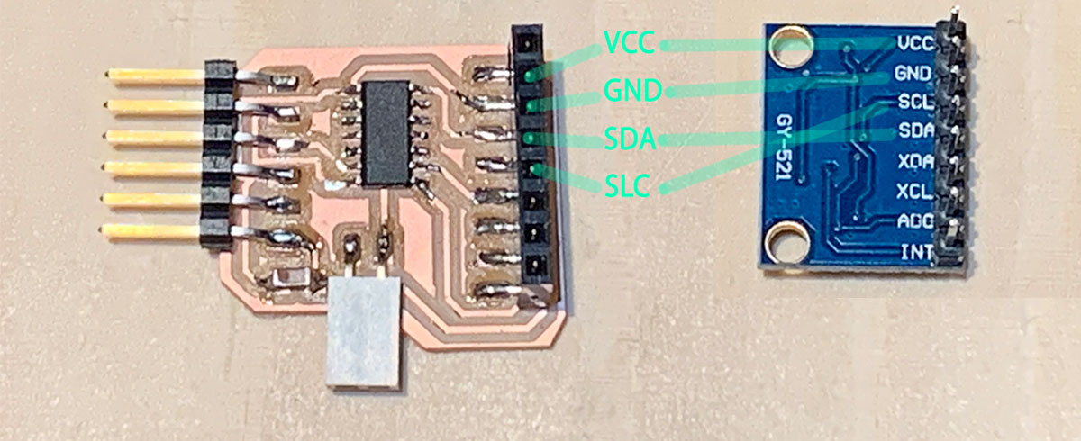
I redesigned the board to correctly align with the accelerometer's pins and repeated the entire process.
Here are the .png files that I used with ModsProject to generate the milling machine files:

You can see the difference between the new board and the old one here:

The new board ended up being smaller than expected, which is advantageous. Since the sensor board has an LED, it was not necessary to add one to the main board.

I encountered an issue with the connection. I mistakenly connected RX to RX and TX to TX instead of RX to TX and TX to RX. After resolving this with Josep, the connections worked fine.

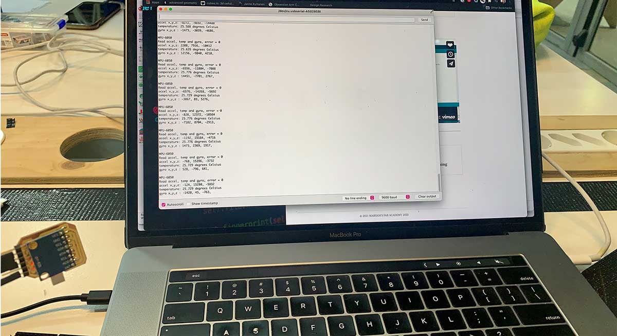
To test the board, I used the same code I had for the Arduino UNO. Carla recommended using the "Upload Using a Programmer" option, and it worked.

I need to clean up this code for the final project, but for now, it was functional and correctly sensing the inputs.
Find the final files here: