9. Embedded Programming
Week Assignment
- Compare the performance and development workflows for different microcontroller families (group).
- Read the datasheet for the microcontroller I’m programming (individually).
- Program the board I made to perform a task, using as many different programming languages and environments as possible (individually).
The Basics
Syntax
Syntax refers to the arrangement of words and symbols used to create code. These rules are essential for writing code that runs correctly. Syntax is similar to grammar in programming; it helps us structure our instructions so that the computer can understand and execute them.
Variable
A variable is a container that holds a piece of information. Different types of variables are used for various kinds of data, and there are general-purpose variables that can hold a variety of values.
int age = 14;

//
int is the data type
age is the variable
14 is the value

"int" data type means that the variable can only hold INTegers.
"double" should be use if we have to store decimals and exponentials
"const" for varialbes that can not be changed
- A variable name can contain only letters, numbers, and underscores (
_). - A variable name cannot start with a number.
- Variable names should not begin with an uppercase letter.
- A variable name cannot be a keyword. For example,
intis a keyword used to denote integers.
Fundamental Data Types
| Data Type | Meaning | Size (in Bytes) | Example |
|---|---|---|---|
| int | Integer | 2 or 4 | int age = 20; |
| float | Floating-point | 4 | float area = 64.74; |
| double | Double Floating-point | 8 | double volume = 134.64534; |
| char | Character | 1 | char test = ‘h’; |
| wchar_t | Wide Character | 2 | wchar_t test = L’ם’ //storing Hebrew character; |
| bool | Boolean | 1 | bool cond = false; //has one of two possible values: true or false. |
| void | Empty | 0 | cannot declare variables. It means “nothing” or “no value”. |
Control Structure
A control structure is a block of code that makes decisions based on variables or other conditions. It allows the code to execute different actions depending on the current state or situation.
if (condition) {
    // Execute this block of code
}
Data Structure
Data structures determine how we store and organize information. Common data structures include lists and arrays.
- Array: An array is a data structure that holds a collection of elements, each identified by an index.
- Array indices start at 0, so
x[0]refers to the first element. - For an array with size
n, the last element is at indexn-1. - Array elements are stored in contiguous memory locations.
- Array indices start at 0, so
Compiling
Compiling is the process of converting your source code into machine code that the computer can execute. This step is crucial for translating high-level programming instructions into a format that the hardware can understand and act upon.
Function
A function is a reusable block of code that can be invoked from multiple locations within a project. Functions encapsulate a set of operations, which means they operate within their own scope and can affect other elements only if explicitly stated. They can accept inputs and return outputs. Functions can be included from external files to reuse code across different parts of a project.
Libraries
Libraries are collections of pre-written code that provide common functionalities and can be reused across multiple projects. They help to avoid duplication of code and simplify complex tasks by providing standard solutions.
Init
Initialization involves setting up the necessary elements before any code execution. This stage is crucial for defining data structures and variables, and assigning them initial values. All essential configurations and declarations should be completed during initialization to ensure smooth operation of the code.
Arduino IDE Basic Steps
- Download the latest version of the Arduino IDE from the Arduino website.
- Open the IDE, navigate to Tools, and select the appropriate board.
- Connect the board to your computer, then go to Tools and select the correct port. Connecting and disconnecting the board may help you identify the correct port.
Sketch
A sketch is the code that you write and upload to the board. Each sketch begins with two built-in functions that are empty by default:
- Setup: This function runs once and is used for initializing settings and configurations for the project, such as pin modes (inputs/outputs).
- Loop: This function runs repeatedly and contains the main code that will be executed continuously.
Variables and data structures should be declared above these two functions to ensure they are properly defined before the setup function is executed.
Programming the Board with Arduino
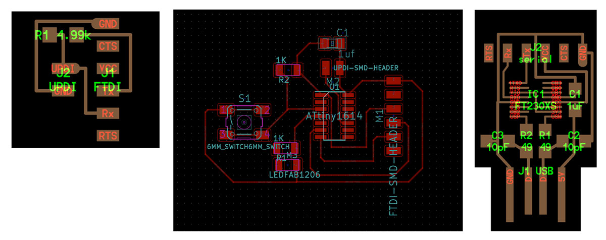
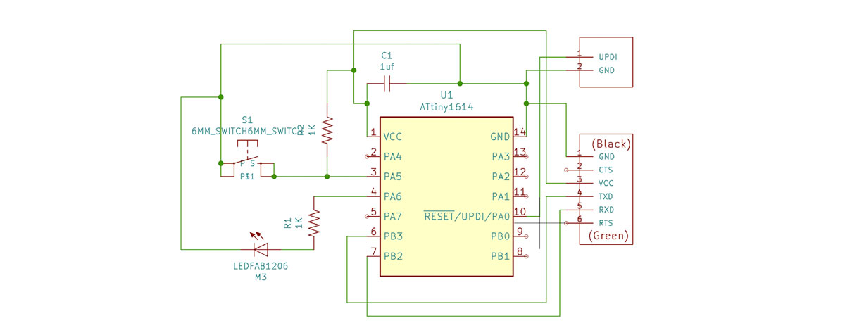
For this assignment, I will use the board I created during the Electronics Design week, which includes an LED and a button. The goal is to turn on the LED when the button is pressed, demonstrating a basic input-output interaction.
I began by reviewing my board and the additional ones (UPDI and FTDI) I developed during the Electronics Production week.
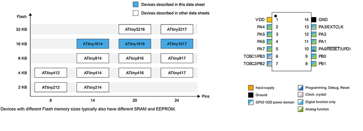
Next, I referred to the datasheet for the ATtiny 1614 microcontroller I used.
What I’ve Learned from the Microcontroller Datasheet
From reading the datasheet, I discovered that this microcontroller has limited memory and a small number of pins, but it’s sufficient for simple projects.
- Number of pins: 14
- Memory: 16 KB
- Clock speeds: 16 MHz and 20 MHz
- Maximum voltage: 6V
An important detail was identifying pin positions. The microcontroller features a small circle engraved on one corner, which is marked as a black circle on the datasheet. This marking helps in correctly orienting the microcontroller.
I utilized the pin map to accurately identify the pin numbers on the microcontroller.
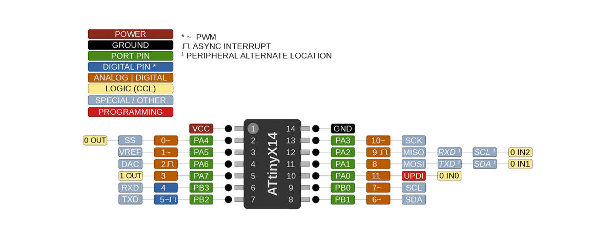
Switch = PA5 = pin 1
LED = PA6 = pin 2
Fortunately, both pins are capable of analog and digital functions. Since I only required digital functionality for an on/off signal, this setup was adequate.
My UPDI connection is on pin 11.
The board connections were made as follows: - TDX (Transmit Data) = PB3 = Digital pin 4 (RXD on the ATtiny 1614) - RXD (Receive Data) = PB2 = Digital pin 5 (TDX on the ATtiny 1614)
RxD stands for Receive Data, and TxD stands for Transmit Data. I mistakenly swapped these connections. However, since I had already uploaded code during the Electronics Design week, I decided to test it as is. If it didn’t work, I would use an Arduino Nano instead.
In order to get the Attiny 1614 board in my Arduino IDE I followed this tutorial and installed the MegaTinyCore package.
/* Test 1
turn on a LED when the button is pressed
turn it off when the button is not pressed (or released)
*/
int pinButton = 1; //the pin where connected to the button
int LED = 2; //the pin connected to the LED

void setup() {
   Serial.begin(9600);
  pinMode(pinButton, INPUT); //set the button pin as INPUT
  pinMode(LED, OUTPUT); //set the LED pin as OUTPUT
}

void loop() {
  int stateButton = digitalRead(pinButton); //read the state of the button if it's press or not
  Serial.println(stateButton); // in order to understand which the values of the button
  if(stateButton == 1) { //if is pressed
     digitalWrite(LED, HIGH); //write 1 or HIGH to led pin
  } else { //if not pressed
     digitalWrite(LED, LOW);  //write 0 or low to led pin
  }
}
With this code, the LED remains on all the time and turns off when I press the button. It seems I inverted the LOW and HIGH values in the code.
/* Test 1
turn on a LED when the button is pressed
turn it off when the button is not pressed (or released)
*/
int pinButton = 1; //the pin where connected to the button
int LED = 2; //the pin connected to the LED

void setup() {
  Serial.begin(9600);
  pinMode(pinButton, INPUT); //set the button pin as INPUT
  pinMode(LED, OUTPUT); //set the LED pin as OUTPUT
}

void loop() {
  int stateButton = digitalRead(pinButton); //read the state of the button if it's press or not
  Serial.println(stateButton); // in order to understand which the values of the button
  if(stateButton == 1) { //if is pressed
     digitalWrite(LED, LOW); //write 1 or HIGH to led pin
  } else { //if not pressed
     digitalWrite(LED, HIGH);  //write 0 or low to led pin
  }
}
I was struggling with Mac and Arduino IDE, but after installing MegaTinyCore and rebooting the computer, everything worked fine. You can follow the installation instructions for megaTinyCore.
Arduino + PyUPDI
I decided to experiment with programming the board using Python. Here’s what I did:
- Opened the terminal and wrote:
 python --version

// and then

 pip install https://github.com/mraardvark/pyupdi/archive/master.zip
pip is a program that lets you install python packages
so I used this command to install pip
sudo easy_install pip
Then I tryed again with
pip install https://github.com/mraardvark/pyupdi/archive/master.zip
brew install python
Then I entered
pip3 install https://github.com/mraardvark/pyupdi/archive/master.zip
pip3 install intelhex pylint pyserial
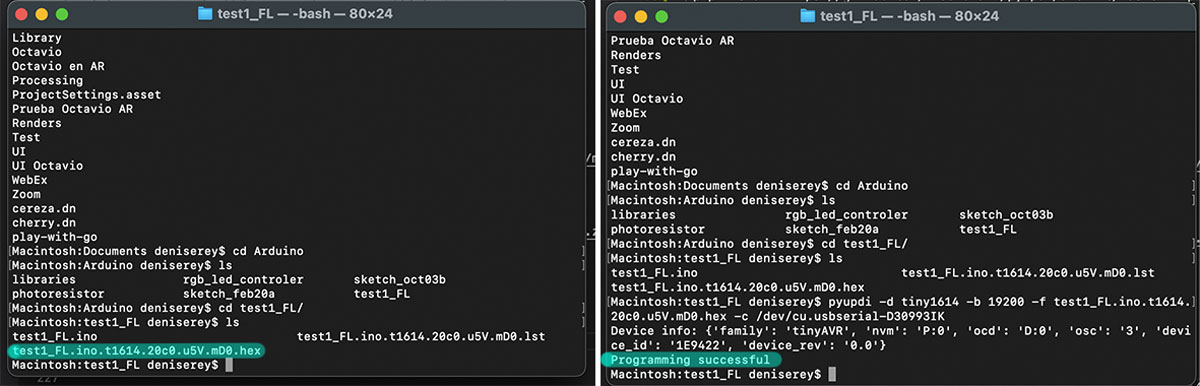
pyupdi lets you interact with the board, so I entered the following line to upload my code to the board.
test1_FL deniserey$ pyupdi -d tiny1614 -b 19200 -f test1_FL.ino.t1614.20c0.u5V.mD0.hex -c /dev/cu.usbserial-D30993IK
I also experimented with Microsoft MakeCode but had trouble finding the option to change the board. Despite this, I found MakeCode to be more intuitive than the Arduino Sketch environment, especially with its ‘Advanced’ features.
Programming My Board with Plain C
To compile and generate the .hex file for uploading to the controller, I followed this tutorial.
Initially, I wrote the following code to make the LED on my board blink:
#define F_CPU 3333333
#include <avr/io.h>
#include <util/delay.h>

#define LED PIN6_bm // Define LED pin
#define DELAY 500 // Define waiting time

int main(){

    PORTA.DIR |= LED; // Define the led port as output

    while(1){
        PORTA.OUT |= LED; // LED ON
        _delay_ms(DELAY); // Wait half a second

        PORTA.OUT &= ~LED; //LED OFF
        _delay_ms(DELAY); // Wait half a second
    }

    return 0;
}
Then, I used the following line to compile the C code for the Attiny microcontroller:
avr-gcc -Wall -g -Os -mmcu=attiny1614 -o main.bin main.c
This line generates the .hex file to upload the controller:
avr-objcopy -j .text -j .data -O ihex main.bin main.hex
Last but not least, the following command uploads the code to the microcontroller:
python3 -u /megaTinyCore/hardware/megaavr/2.2.9/tools/prog.py -t uart -u /dev/cu.usbserial-A50285BI -d attiny1614 -v --fuses 2:0x02 6:0x04 8:0x00 -f ./main.hex -a write
I’ve learned that handling the states of the microcontroller requires understanding bitwise operations. For example, using PORTA.OUT |= LED; // LED ON can control the state of a pin directly. Initially, I didn’t grasp why this works as it does, which made me appreciate the convenience of the Arduino IDE even more.
Basics on How to Choose a Microcontroller
-
Bits: Microcontrollers come in various bit rates, such as 8-bit, 16-bit, and 32-bit. The number of bits refers to the size of the data lines, which influences the amount of data that can be processed. Most Arduino boards use an 8-bit AVR microcontroller from Atmel. More bits generally mean better performance, but they also increase cost and power consumption.
-
Frequency: This refers to the speed at which the microcontroller operates.
-
Clock Speed: This is the rate at which the development board processes data. For instance, the Arduino Uno operates at a clock speed of 16 MHz. A higher clock speed improves performance for time-sensitive or data-intensive tasks, but also increases power consumption. For battery-powered projects, choosing a microcontroller with a lower clock speed is advisable.
-
Number of I/O Pins: Consider the number of input and output ports and pins required for your project.
-
RAM: This is where the microcontroller stores variables and arrays (DATA).
-
Energy Consumption and Requirements: Different microcontrollers operate at different voltages, such as 5V or 3.3V. Lower voltage microcontrollers generally consume less power.
-
Memory: Various types of memory are used in microcontrollers:
- Flash Memory: Where the code (Arduino sketch) is stored. The size of the program is shown in the IDE notification window after uploading.
- SRAM (Static Random Access Memory): Used for variables and data manipulation while the sketch is running. For instance, each pixel on an OLED display requires 3 bytes of SRAM for color information. A 128x64 monochrome display needs 1KB of SRAM due to its high resolution.
-
EEPROM (Electrically Erasable Programmable Read-Only Memory): Used for storing long-term information that needs to persist across power cycles.
-
Communication: USART (Universal Synchronous/Asynchronous Receiver/Transmitter) facilitates communication via a serial port using the RS-232C protocol. Some ATtiny microcontrollers lack a hardware USART module, limiting their serial communication capabilities. For detailed comparison, refer to this useful Attiny Chart.
Compare Two Microcontroller Families
For this part of the assignment, I decided to compare the ESP32 and the ATtiny1614. The ATtiny1614 is part of the 8-bit AVR microcontroller family, while the ESP32 is a series of System on Chip (SoC) devices. Below are some key differences and features of each:
ATtiny1614
- Family: 8-bit AVR microcontroller
- Processor: ATtiny1614 features an 8-bit AVR processor.
- Clock Speed: Typically up to 20 MHz.
- Memory: 16 KB Flash memory for storing code, 2 KB SRAM for runtime data.
- I/O Pins: 14 I/O pins.
- Communication: Limited to USART, SPI, and I2C.
- Power Consumption: Low power consumption, suitable for battery-operated projects.
- Special Features: Simple and cost-effective for basic applications. Ideal for projects requiring straightforward I/O and low processing power.
ESP32
- Family: System on Chip (SoC)
- Processor: Dual-core Tensilica Xtensa LX6 microprocessor.
- Clock Speed: Up to 240 MHz.
- Memory: Typically 4 MB Flash memory and 520 KB SRAM.
- I/O Pins: Up to 34 GPIO pins.
- Communication: Extensive communication options including WiFi, Bluetooth (Classic and BLE), USART, SPI, I2C, and more.
- Power Consumption: Low power consumption with multiple sleep modes, though higher than ATtiny1614 due to additional features.
- Special Features: Integrated WiFi and Bluetooth, high processing power, suitable for complex applications requiring wireless communication and high performance.
Summary: The ATtiny1614 is a good choice for simple, cost-effective projects with basic I/O needs and low power requirements. In contrast, the ESP32 offers high performance, extensive connectivity options, and is suitable for more complex applications requiring wireless communication and significant processing power.
| Specifications | ESP 32 | Attiny1614 |
|---|---|---|
| Type | 32 bit | 8 bit |
| Data memory | 4Mb | 256b |
| ADC | 18 | 10 |
| GPIO | 34 | 12 |
| Flash Memory | 16Mb | 16Mb |
| SRAM | 520kb | 2 KB |
| f_CPU (max) | 240MHz | 20 MHz |
Flash Programming and Debugging Protocols
-
ATtiny1614: Programmed via the UPDI (Unified Program and Debug Interface) protocol. UPDI uses a single bi-directional wire that acts as a serial port. The reserved UPDI pin on the ATtiny1614 triggers a reset when the voltage is set to 0V.
-
ESP32: Can be programmed in two main ways:
- Serial Port 0: Connects directly to the ESP32’s serial port for programming.
- Over the Air (OTA): Allows programming over WiFi. The ESP32 opens a web socket when connected to WiFi, handling the transfer and flashing process.
I followed these steps when programming the Barduino for Mechanical & Machine Design week.
Check Mechanical & Machine Design week for an example of how to program the ESP32.
Check Electronics Design for an example of how to program the ATtiny1614.
Tip
Throughout the process, one of the most important things I learned is that memory is crucial for handling graphics due to their large size. Additionally, be mindful of the size of libraries, as they can be quite heavy. Prototyping with breadboards and carefully selecting libraries can save space and energy.
Personally, I found that while the ESP32 offers significantly more power than the ATtiny1614, it’s important to assess the project’s needs. Using a more powerful microcontroller like the ESP32 can lead to higher energy consumption, requiring larger batteries. Choosing the appropriate microcontroller based on the project requirements can help save space and energy.