Final Project - Tracking Page
This is the page for tracking my final project: Cultural Memory Globe
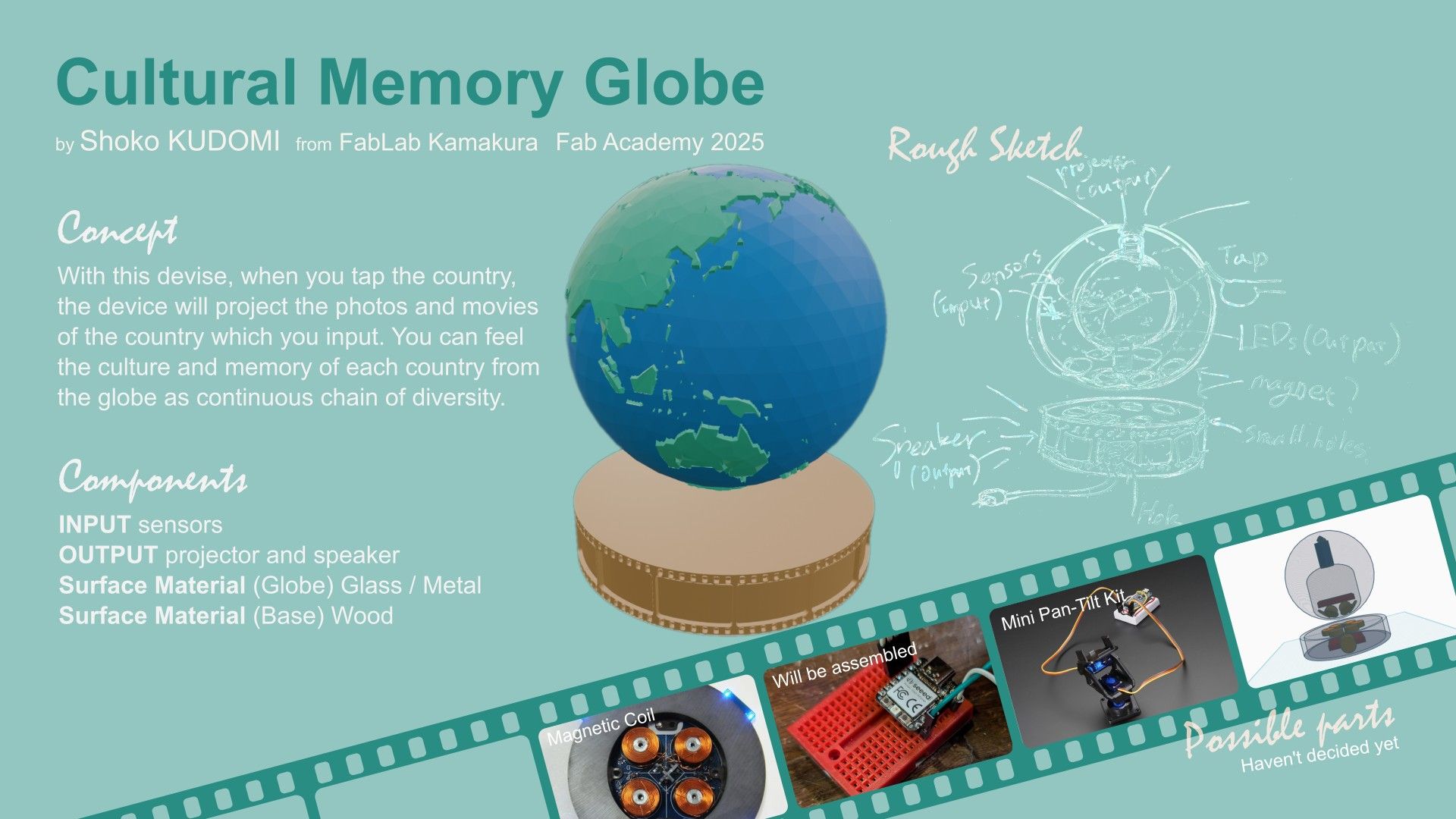
About My Final Project: Cultural Memory Globe
I love traveling. Why? It is because I like to feel the difference of each unique local nature, culture, and people’s lives of each places. These days we can learn differences between different areas of the earth through the internet or SNS, and feels as if we know about it. However, once I visit the place actually, I really understand what is the place like. Through the final project, I would like to create something make you feel uniqueness of each places and cultural graduation of the world. This would be also nice to record my travel memories with actual feeling.

Contents
Planning
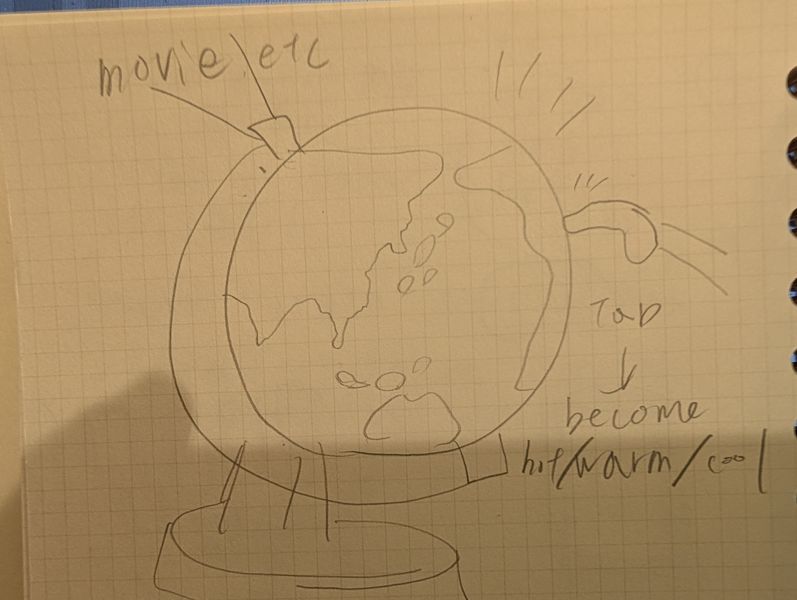
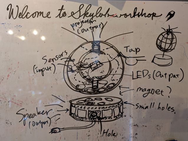
First Sketch
This is my first sketch of the device.
Features
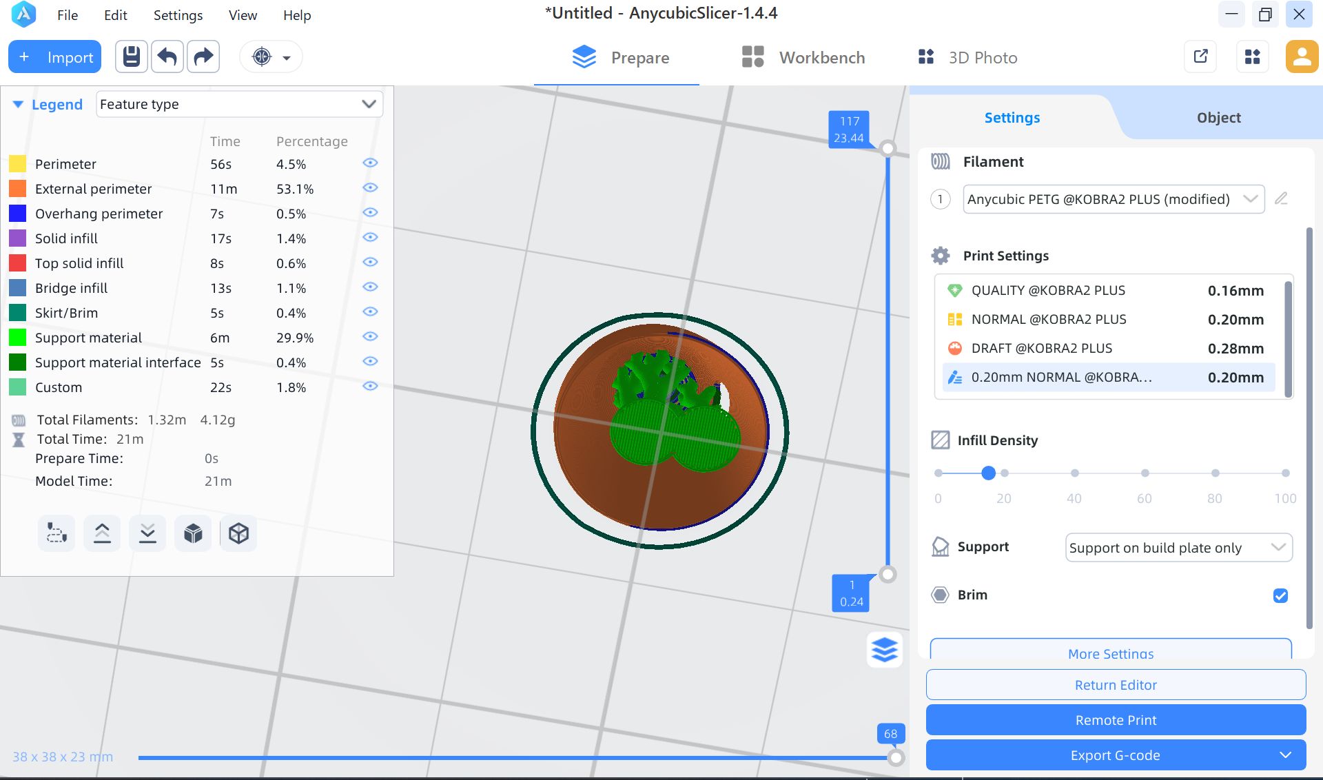
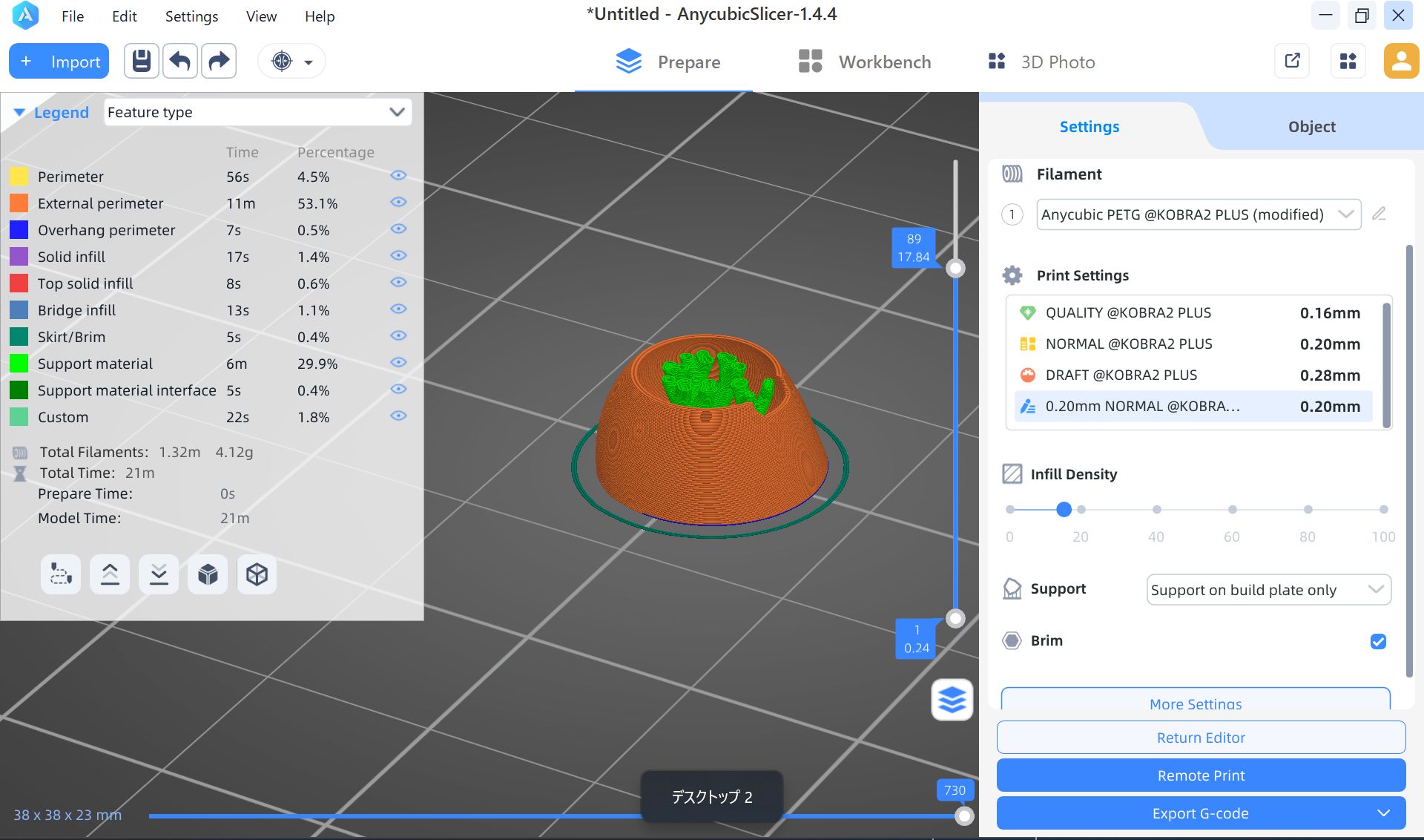
Basically, this device consists of 2 parts: globe and base. When you choose the country on the globe, the device will project the photos/videos of the country, and also, if possible, it shows the temperature of the place with LEDs or heat.Basic Function
- INPUT : Tap a country you want
- OUTPUT :project the photos/videos of the country/change temperature of the device
- Surface Material (Globe): Not decided(Glass or metal?)
- Surface Material (Base): Wood
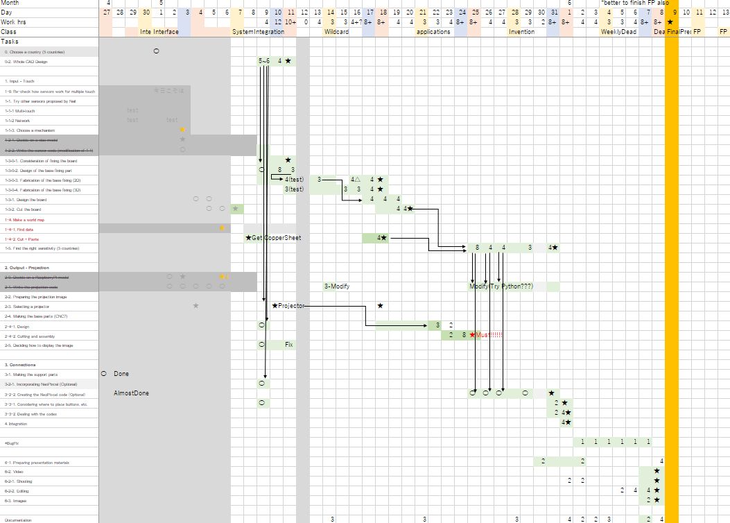
Schedule
Then, I made plan for each week (Just in case my job get too much busy).| # | M | D | Class | Plan |
|---|---|---|---|---|
| 1 | Jan | 22 | principles and practices, presentations, introductions, project management | Finish my rough sketch |
| 2 | 29 | computer-aided design | Model the device | |
| 3 | Feb | 05 | computer-controlled cutting | Try to make/think about base part |
| 4 | 12 | embedded programming | Try to program the function of tap and glow | |
| 5 | 19 | 3D scanning and printing | Try to make inside of the device / print out glove part | |
| 6 | 26 | electronics design | design the electronics of the device | |
| 7 | Mar | 05 | computer-controlled machining | - (Make something big) |
| 8 | 12 | electronics production | Cut/print the electronics of the device | |
| 9 | 19 | input devices | Try to make sensor parts | |
| 10 | 26 | output devices | Try to make speaker/projector parts | |
| 11 | Apr | 02 | networking and communications | Try to make signals between globe part and base part |
| 12 | 09 | mechanical design、machine design | - (group assignment week) | |
| 13 | 23 | molding and casting | Try to create a mold for casting the globe | |
| 14 | 30 | interface and application programming | Try to make app which can add/manage photos | |
| 15 | May | 07 | system integration | Try to make it integrated |
| 16 | 14 | wildcard week | Try to cast the globe part with (possibly) glass? | |
| 17 | 21 | applications and implications,project development | - | |
| 18 | 28 | invention, intellectual property, and income | - | |
| 19 | Jun | 06 | weekly assignments deadline | - |
| 09- | final project presentations | - |
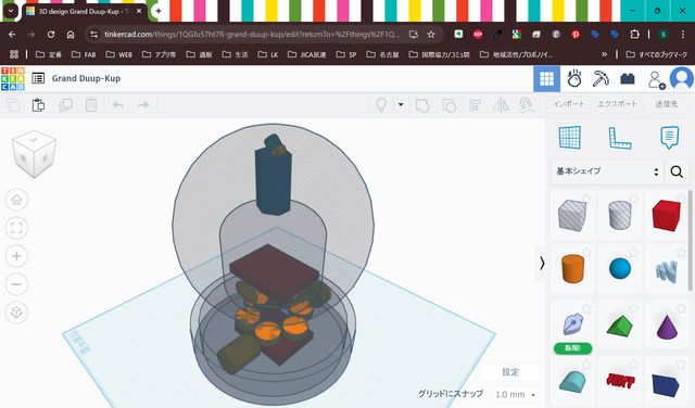
3D Modeling(Week2)
In week 2, I tried modeling of the device. First, I mage a rough sketch for modeling.
Then, I model it as follows:
- Think and design overall structure of the device with Tinker Cad
- Modeling for ‘Globe’ part with Blender
- Modeling for ‘Base’ part with Fusion
- Combine Globe and Base in Blender
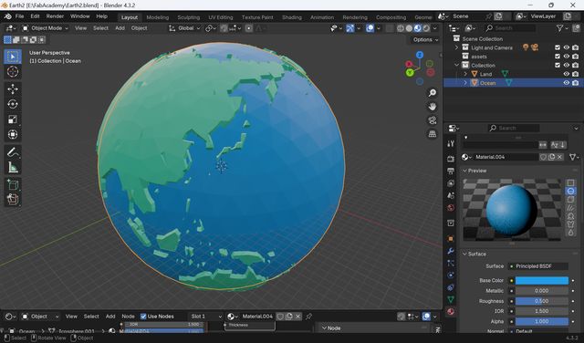
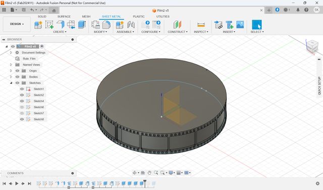
For the details, please see Week2 Computer-Aided Design page.
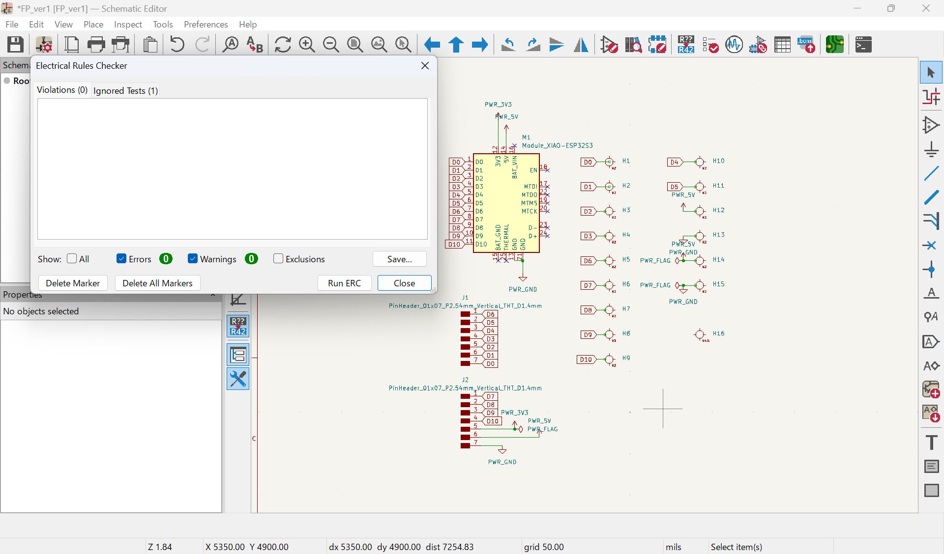
Electronics
Electronics Design(Week6)
In week 6 I searched about possible processors/microcontroller and configurations.
| Board | ESP32 | Seeed Studio XIAO ESP32S3 | Seeed Studio Xiao ESP32C3 | Seeed Studio XIAO ESP32C6 | Arduino Nano | Raspberry Pi Zero W (Projection) |
|---|---|---|---|---|---|---|
| Microcomputer | ESP32 | ESP32S3 | ESP32C3 | ESP32C6 | ATmega328P | RP3A0 |
| Datasheet | esp32_datasheet_en.pdf | esp32-s3_datasheet.pdf | esp32-c3_datasheet_en.pdf | esp32-c6_datasheet_en.pdf | A000005-datasheet.pdf | https://www.raspberrypi.com/products/raspberry-pi-zero-w/ |
Final configuration plan at week 6
During the Lab session, I was advised that if touch + projection is required, the following configuration example would be good. As expected, a Raspberry Pi is required instead of a microcontroller to project videos.
| Application | Microcontroller | Input | Output |
|---|---|---|---|
| Touch input detection | xiao (RP2040 or ESP32) |
step response (need to decide numbers) |
- |
| Projection | Raspberry Pi | - | projector (need to be chosen) |
Input - Step Response(Week9)
In week 9, I try out various types of touch sensors.
- Processor (xiao ESP32S3)
- 1 pin with Resistor (xiao RP2040)
- 2 pin (xiao RP2040)
- MPR121 (xiao ESP32C3)
Results
The results for xiao ESP32S3 are as follows:
| Pin | Figure |
|---|---|
| T1 | 28600 |
| T2 | 27500 |
| T3 | 32000 |
| T7 | 30700 |
| T8 | 29100 |
The results for 1 pin with Resistor are as follows:
Horizontal: Length of wire × Vertical: Size of resistor
*I couldn't figure out the N/A part very well.
| No wire(board direct) | 25cm(thick) | 25cm(0.2㎜²) | ||
|---|---|---|---|---|
| 1 | 100k | 7500-15000 | 500 | 200 |
| 2 | 100k | ~15000 | 1000 | 200 |
| 3 | 1M | N/A | N/A | N/A |
| 4 | 1M | ~10000 | 6-700 | 400 |
| 5 | 2M | 8000~20000 | N/A | 500 |
For the details, please see Week9 Input Device page.
Progress after week 9
After Neil's feedback from week11 class time, I also tried various step response
options for add more pins(=countries).
I tried:
- MultiTouch
- Networking
Touchpad
Capacitive Multitouch
FabLabKamakura Document
After consideration, as for 1st spiral, I decided to use XIAO ESP32S3 for basic
function.
It function well(send/receive) with only 1 pin, and Arduino code is also easy to
understand for me.
I would like to add more pins(= countries) for 2nd/3rd spiral.
For the board making, please see Fabricationsection.
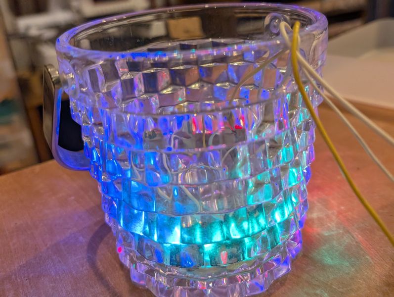
Output - NeoPixels(Week10)
For this week, I try to use Neopixels to light up the sphere.
First I connected it to the S3 and tested it.
It worked fine at first, but then it stopped working, so I used the C3 to test
different ways of
lighting it up.
I also thought about how to display it.
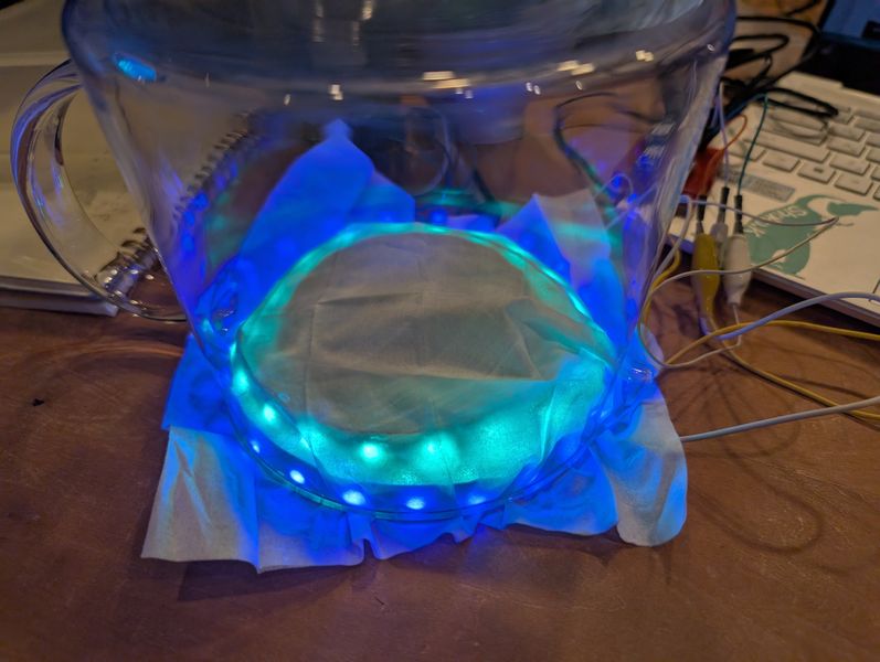
For the details, please see Week10 Output Device page.
Progress after week 10
I made various rainbow design for NeoPixel animation. (Please see programmingsection)
Also, after few trial, I decided to use RP2040 to control NeoPixels because:
- It seems XIAO ESP32S3 doesn't work well with NeoPixel
- I would like to use as many pins as possible as touch sensors
Communication - I2C(Week11)
For week 11, I tried some communication especially for FP:
1. Use xiao ESP32C3 as WiFi server
2. Communicate with Raspberry Pi with I2C
3. Projection test for Raspberry
NeoPixel - On/off with browser
I tried to turn on and off NeoPixel from the browser.
I made it from ”SimpleWiFiServer” test code and the code I made last week for
NeoPixel.
Code is on week 11 page
It worked!
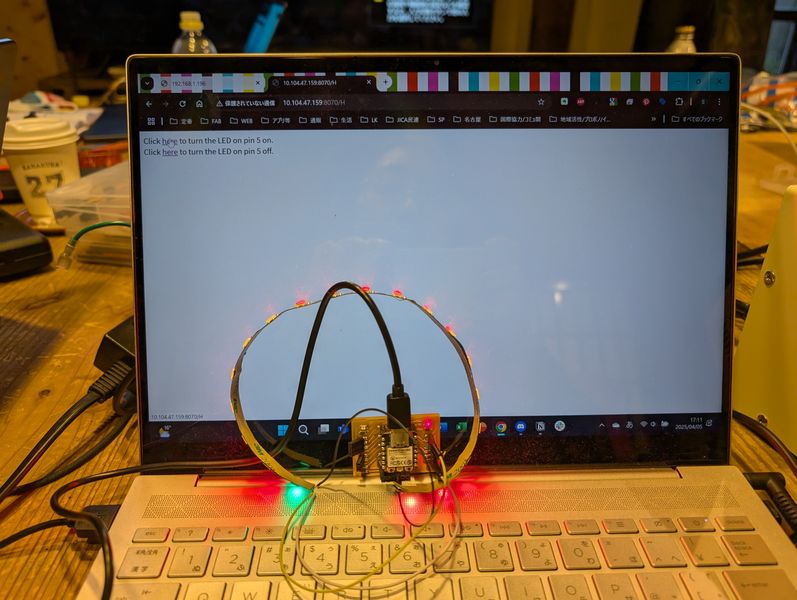
However, the NeoPixel were lighting up a little strangely. This will need to be adjusted if I use it finally.
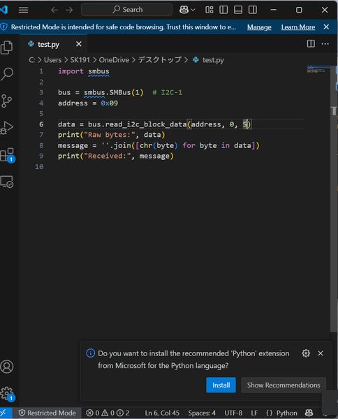
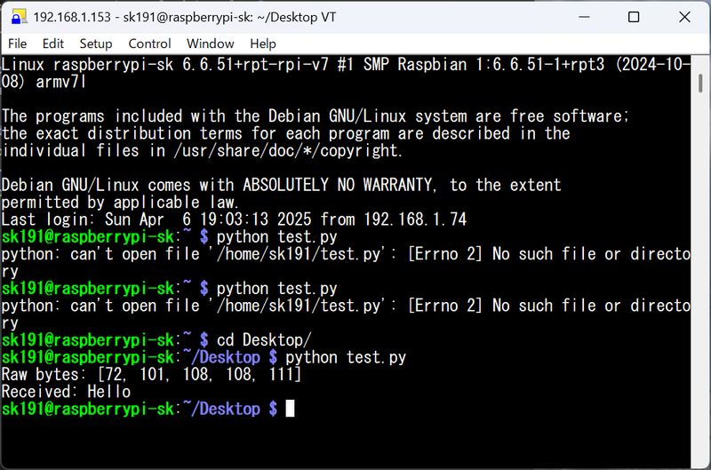
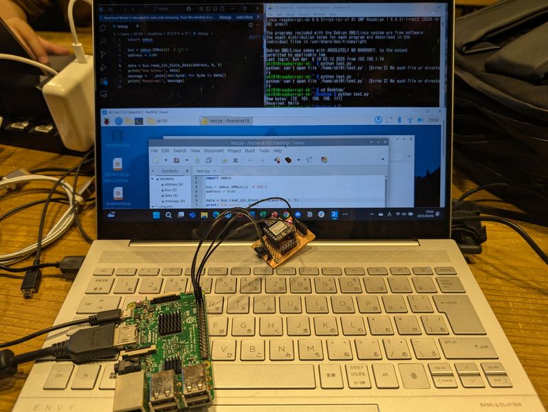
2.I2C - Raspberry Pi(Master)-ESP32C3(Slave)
In the Final Project, I want to use a Raspberry Pi for projection, so I tried
communicating with
Raspberry Pi.
Load the slave code into Xiao. I used the code provided by Maki-san. (code is on week 11 page)
Check the connection with “i2c detect” command
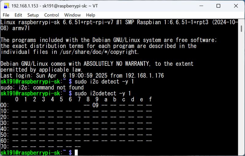
Make master code into python (helped by Tsuchiya-san). The behavior differed slightly depending on the library, and it was difficult to get it to respond properly, but after adjusting various things, I was able to get it to work well with the following code.
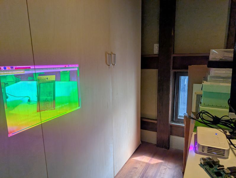
Testing video processing capabilities by version
I sent video data to Raspberry Pi and did a playback test.
Raspberry Pi Zero → Not smooth
Raspberry Pi 3 → Somewhat not smooth
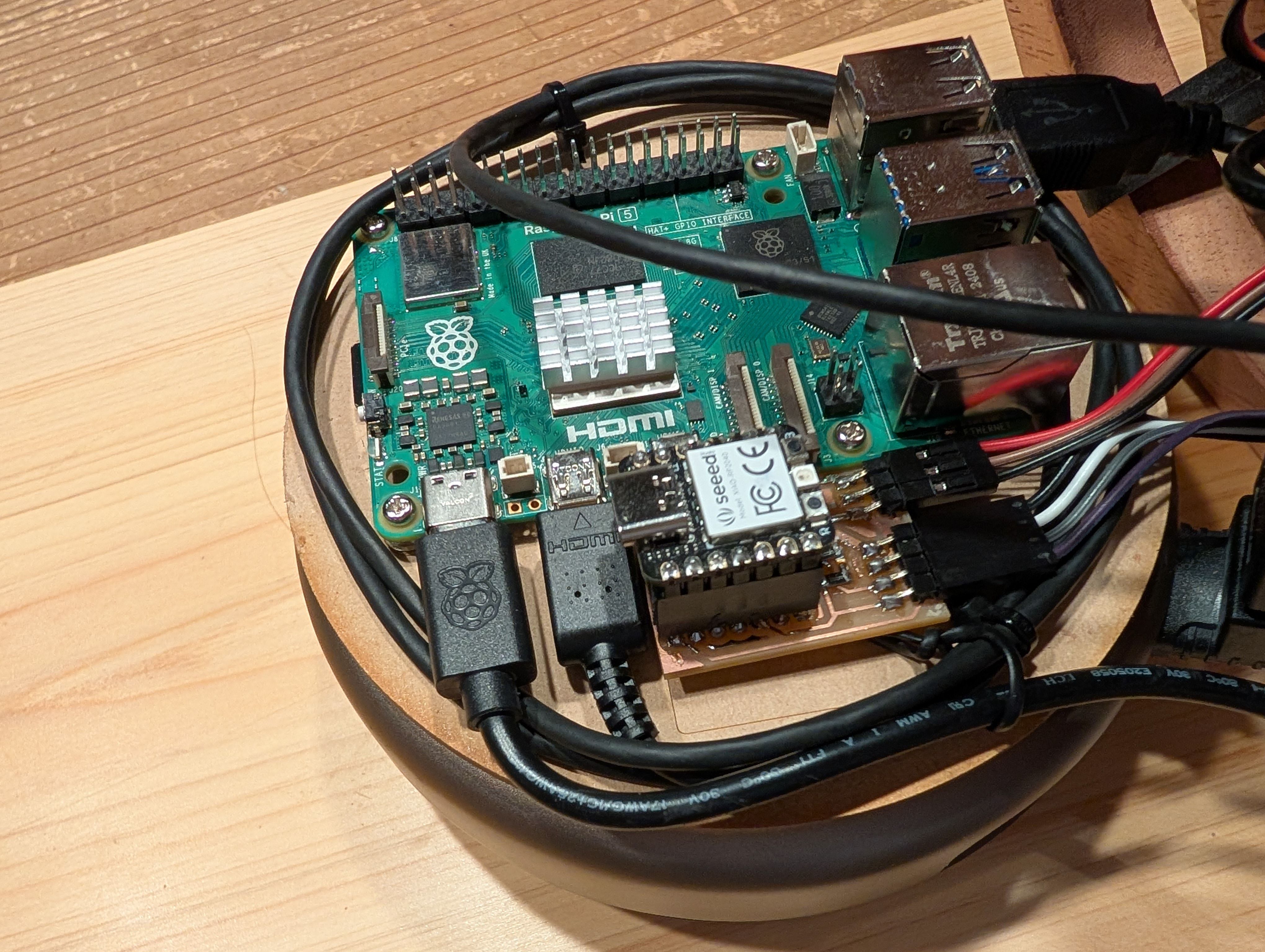
Raspberry Pi 4 → OK
Raspberry Pi 5 → Super smooth
Progress after week 10
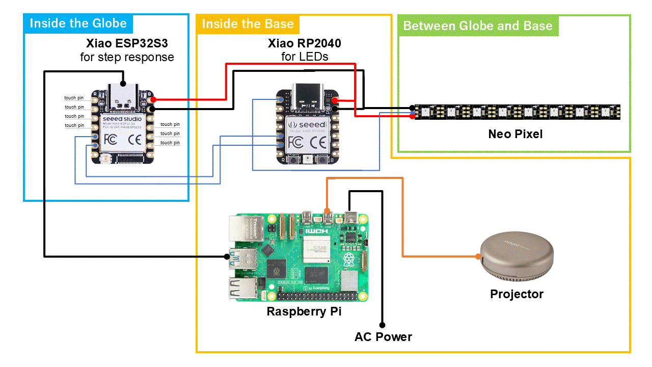
Finally, I decided to use I2C for connecting XIAO ESP32S3(for step response)as Prime
and XIAO RP2040(for NeoPixels) as Secondary.
I also use serial communication between XIAO ESP32S3 and RaspberryPi 5(for
projection) with Processing.
(For more details, please see programmingsection)
Set up for Raspberry Pi
- Installing the Raspberry Pi OS
- How to control it remotely
- How to set up WiFi
- How to send files
- How to enable I2C
I worked on these with the help of Tsuchiya-san
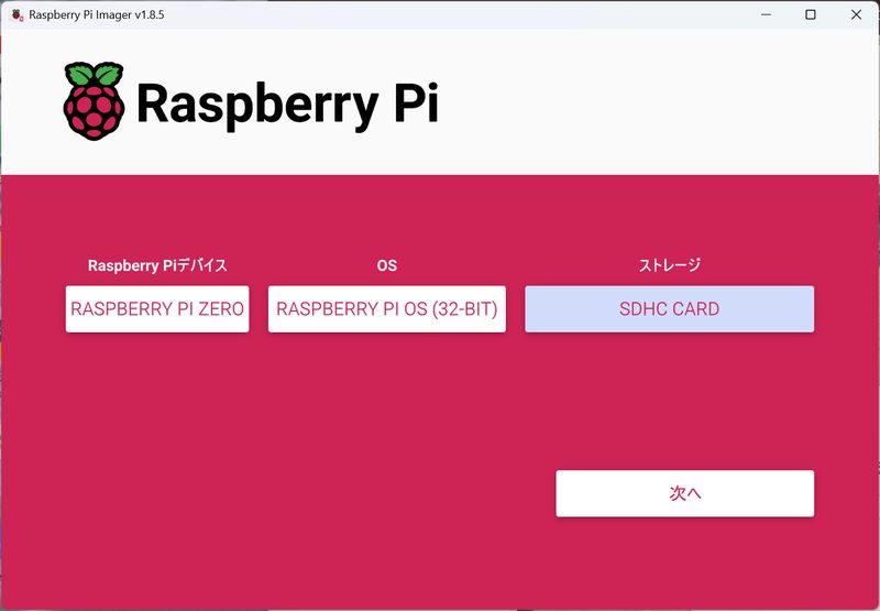
Installing the Raspberry Pi OS
Download OS from here: https://www.raspberrypi.com/software/Install OS to SD card
Reference:
https://pages.switch-science.com/Pi400GS/3_installing_raspberry_pi_os.html
https://raspi-school.com/getting-started-with-raspberrypi/
https://raspi-school.com/getting-started-with-raspberrypi/
Settings: Choose OS (filtered by device), and select SD card as strage
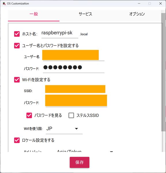
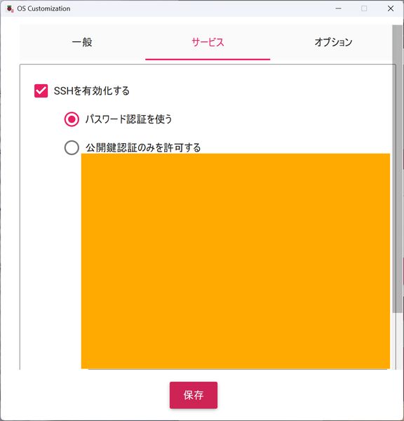
How to control it remotely
To connect remotely, the following Wi-Fi settings are required during the OS installation phase.- set host name, user name and password
- set Wi-Fi
- Enable SSH
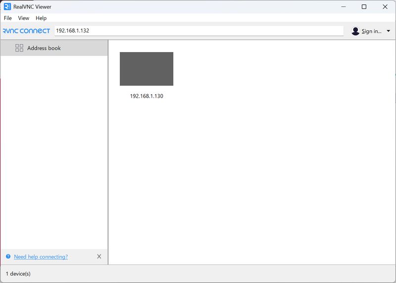
Remotely connect to the Raspberry Pi from the terminal (you can connect with a
username and IP address)
VNC settings (allow remote access)
Open the VNC viewer and enter the IP address to access
*Do not disconnect the WiFi connection when you want to connect remotely!!!
You can also add new WiFi
*You should download VNC viewer for remote desktop:
Open VNC Viewer, and set Username and pass
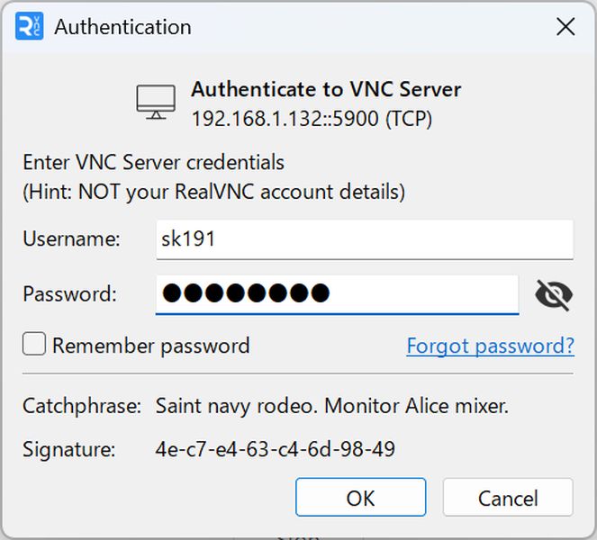
Choose address, and you can operate Raspberry Pi remotely
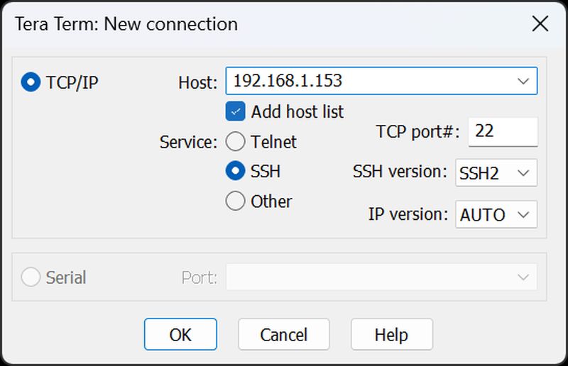
*Above is GUI, but you can also control it with CUI
I used Tera Term
https://teratermproject.github.io/
https://github.com/TeraTermProject/teraterm/releases
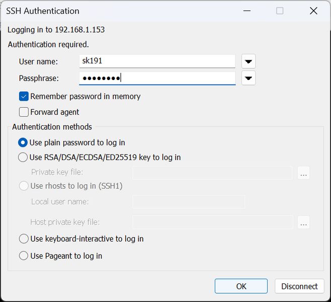
Choose TCP/IP, set Host as Raspberry Pi address, select SSH and connect
How to set up WiFi
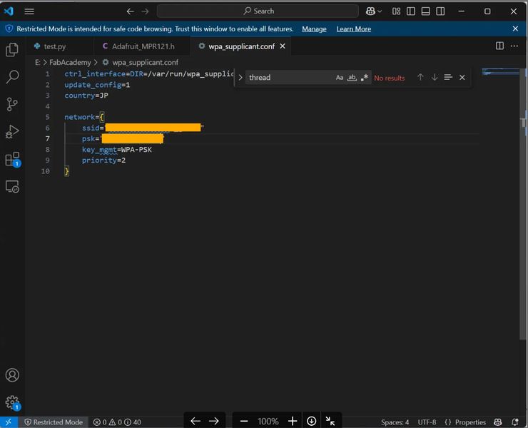
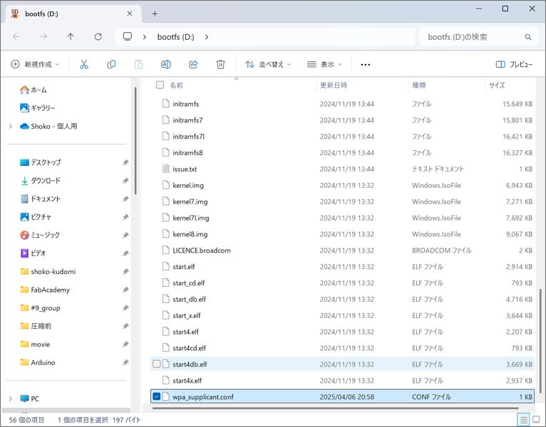
- Create “wpa_supplicant.conf” file.
- Load the created file onto the SD card with the OS.
- Connections are made in order from the top. List the primary at the top.
- The file will disappear after being loaded once. It is loaded into the system.
- When new connection destinations are added, the file will be recreated and loaded again.
Reference: https://qiita.com/otibosi/items/115d4b85d386fa670a58
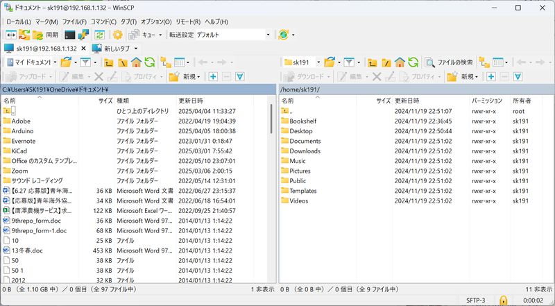
How to send files
Put files into Raspberry Pi via SFTP connection
Install FTP software (winSCP)
https://forest.watch.impress.co.jp/library/software/winscp/download_10950.html
login and connect to the address with SFTP
You can now send and receive files between your PC and Raspberry Pi.
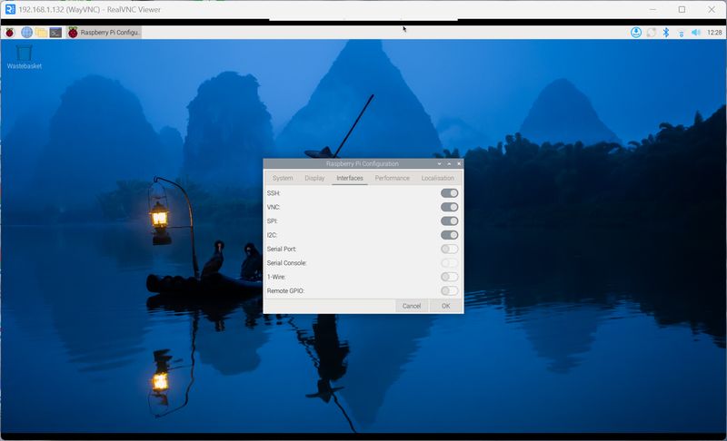
How to enable I2C
Open Raspberry Pi Config and enable I2c.
For the details, please see Week11 Networking and Communications page.
Midterm
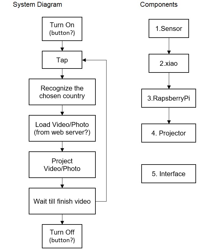
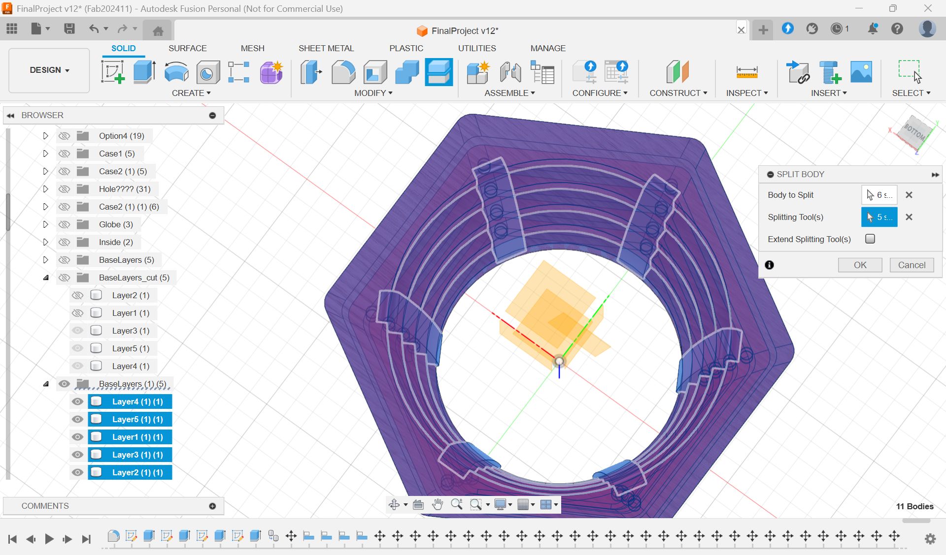
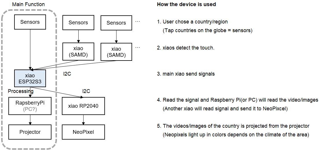
System Diagram
Task List
- 0. Choose Country for 1st spiral
- 1-1. Try other sensors suggested by Neil
- 1-2. Choose the mechanism
- 2-1. Make code for sensors
- 2-2. Find the right sensitivity
- 2-3. Decide xiao model
- 3-1. Decide RaspberryPi Model
- 3-2. Make code for projection
- 4-1. Choose projector
- 4-2. Decide how to show the images
- 5-1. Make Globe parts(Sandblasting?)
- 5-2. Make Base parts(CNC?)
Schedule for the remaining week
Fabrication
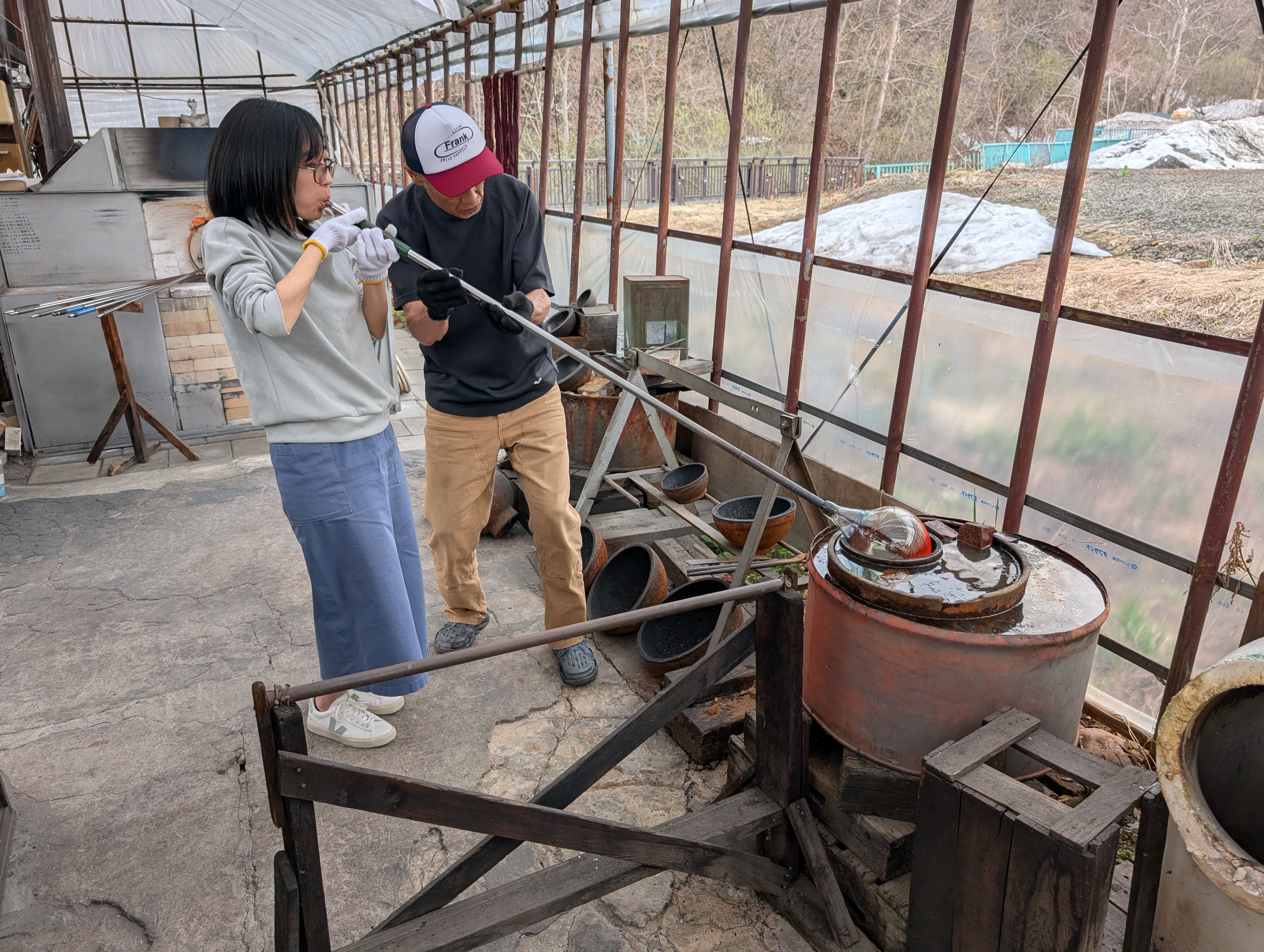
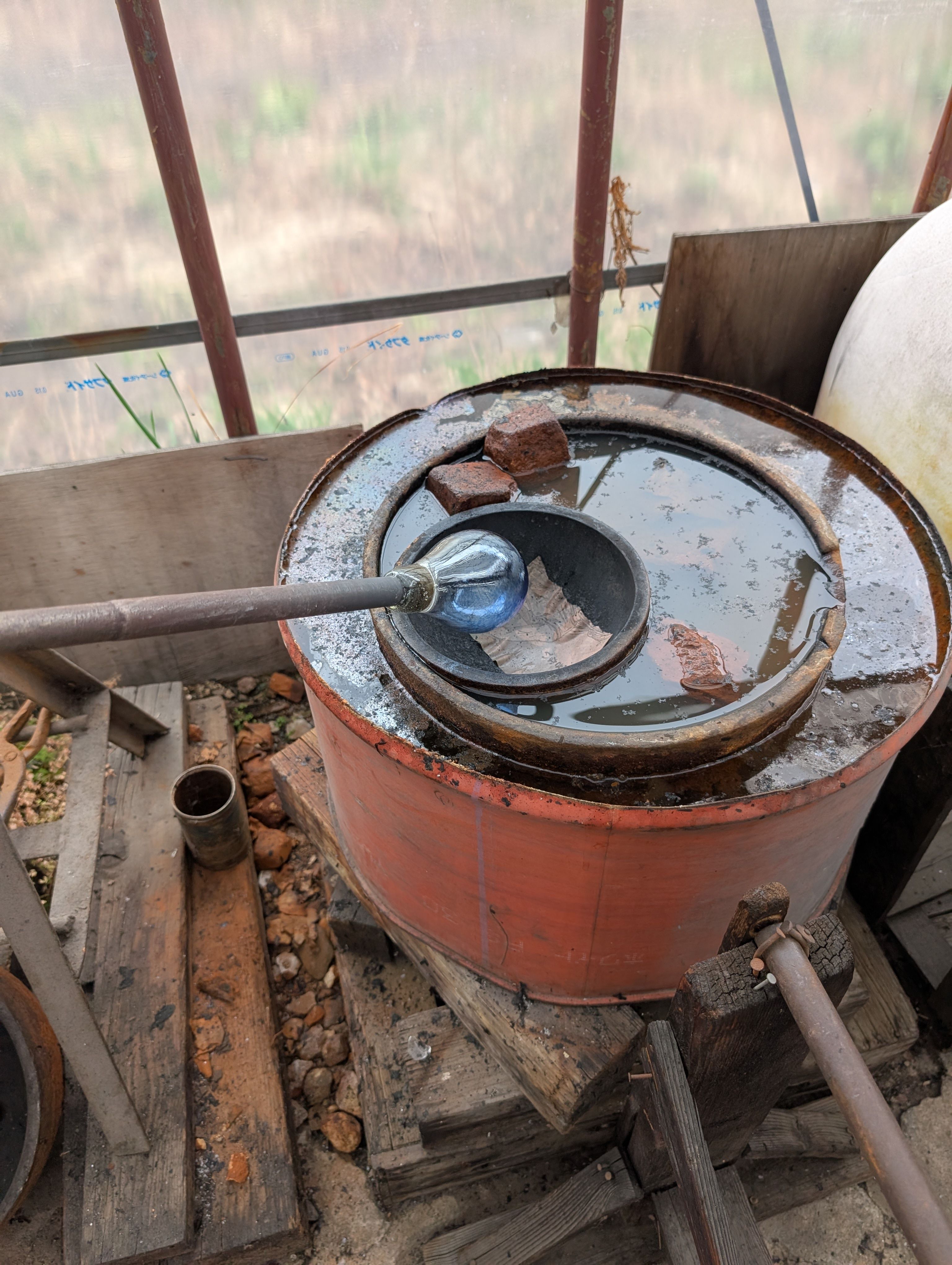
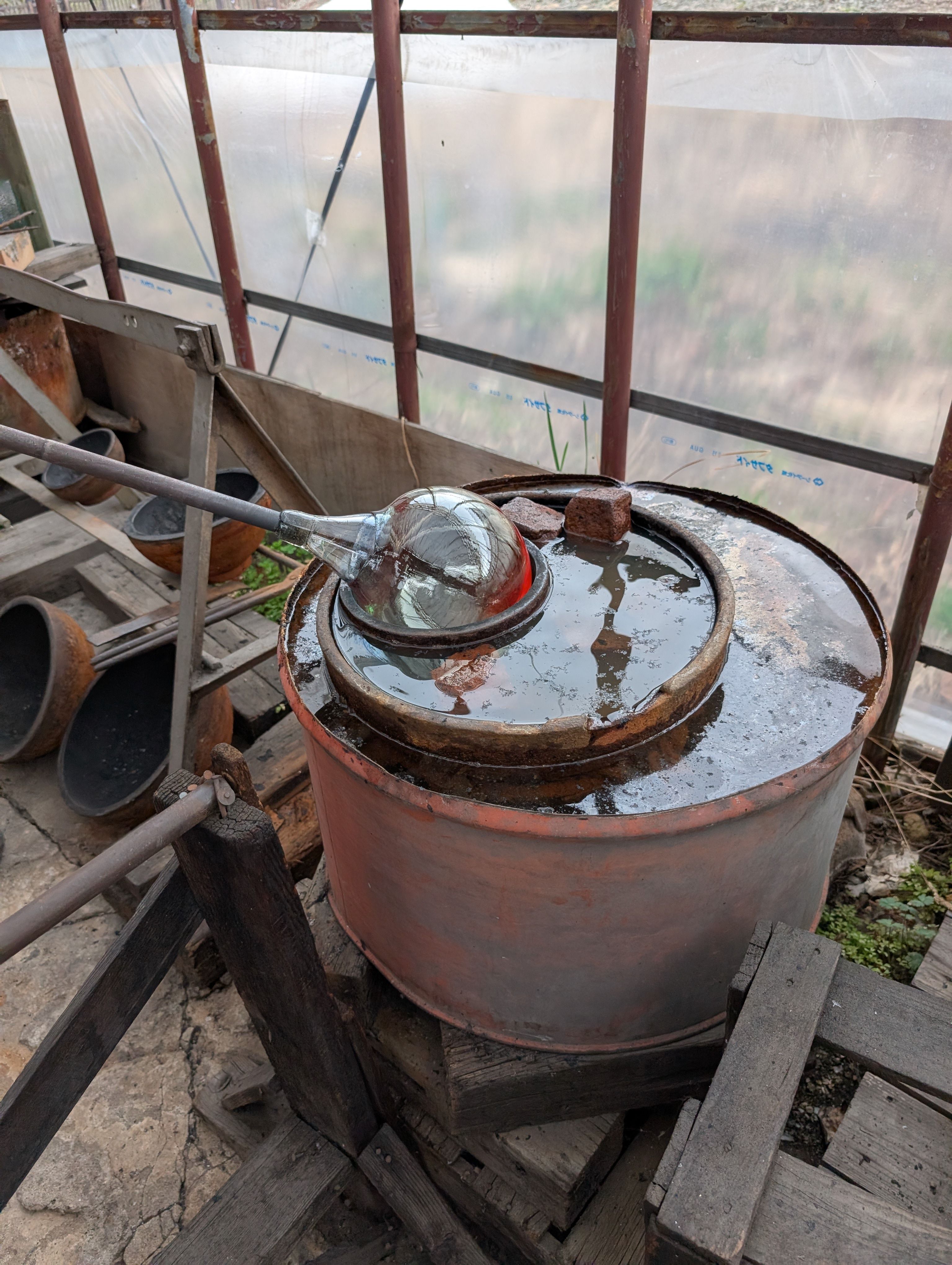
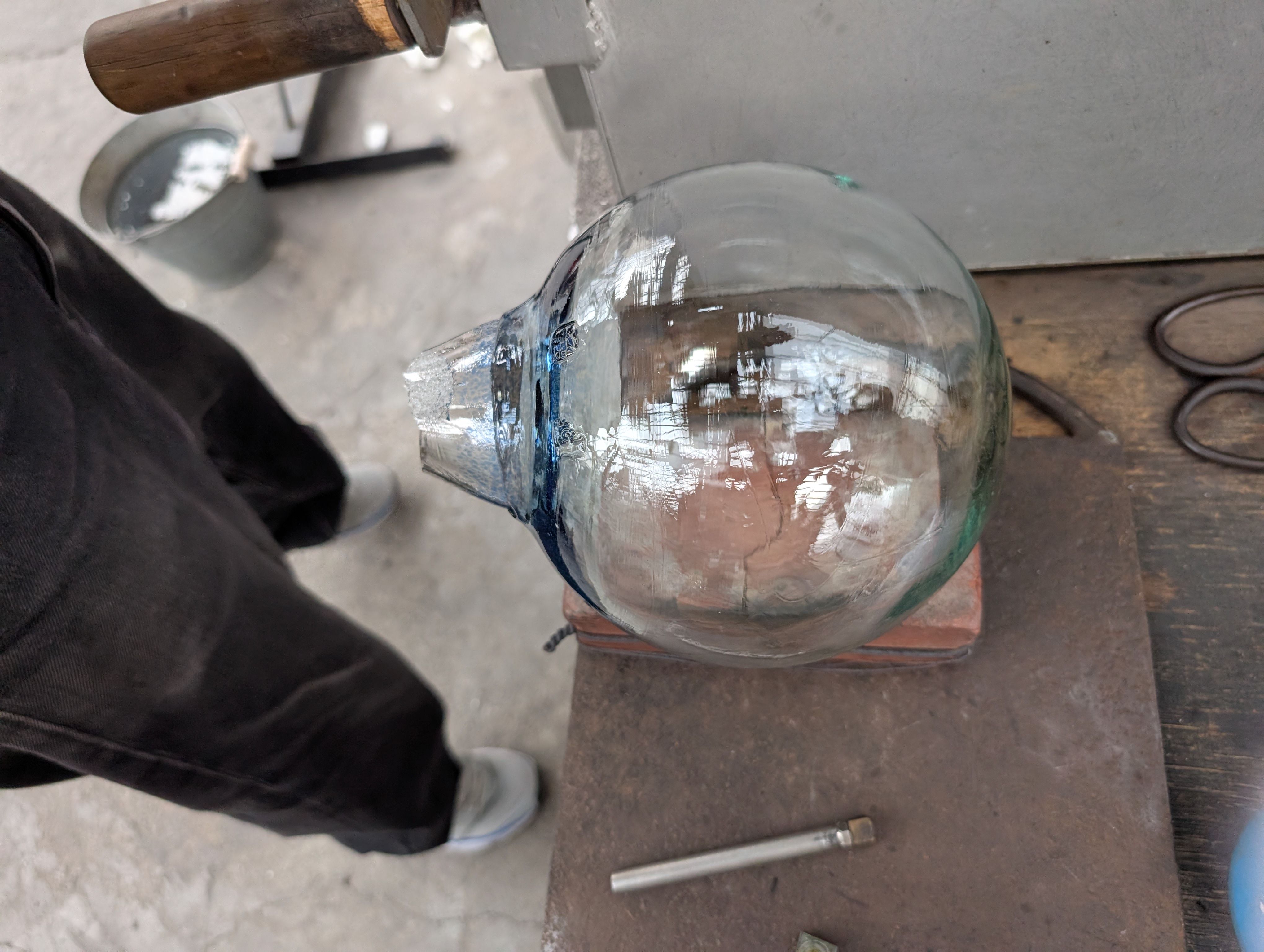
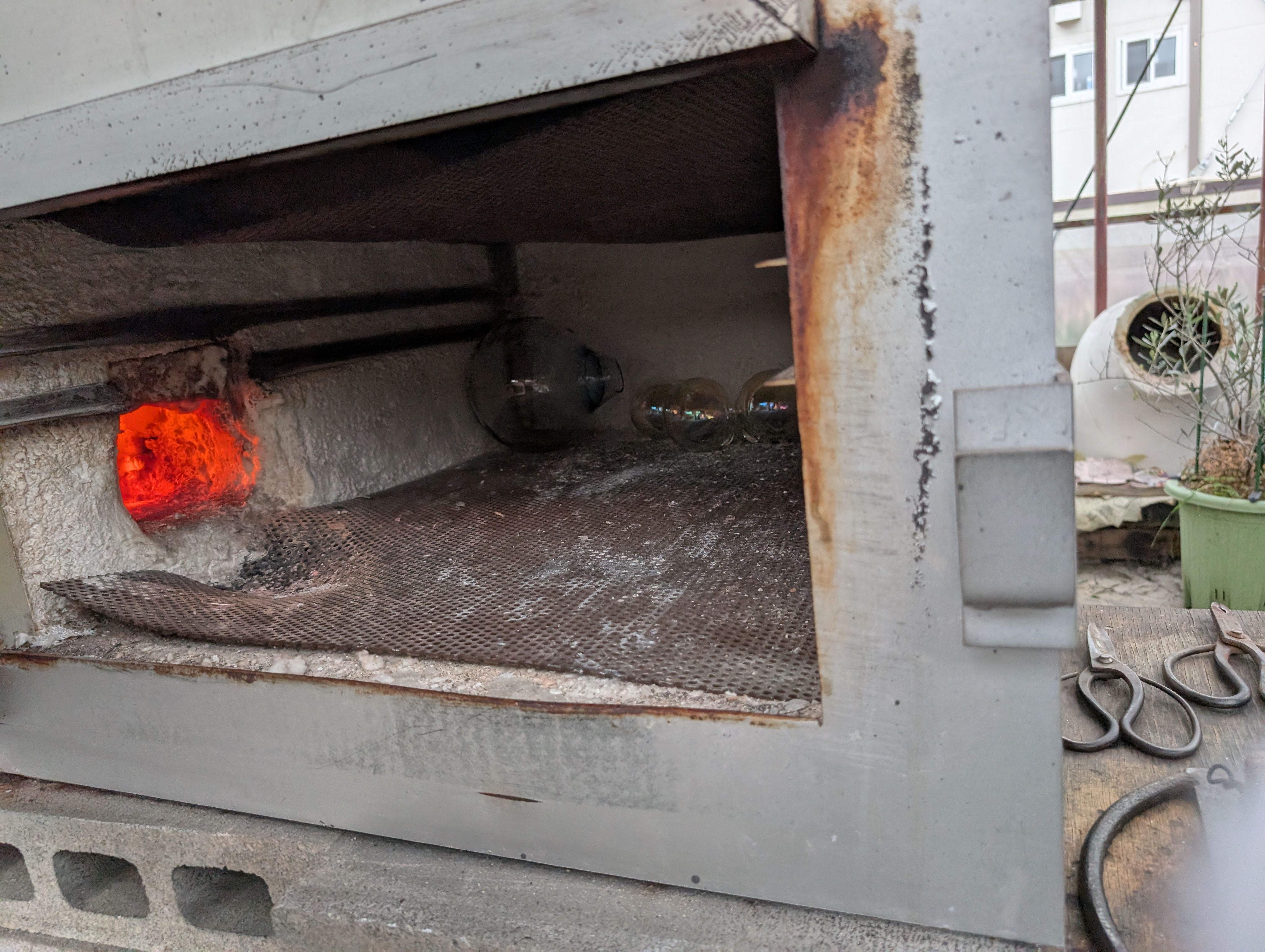
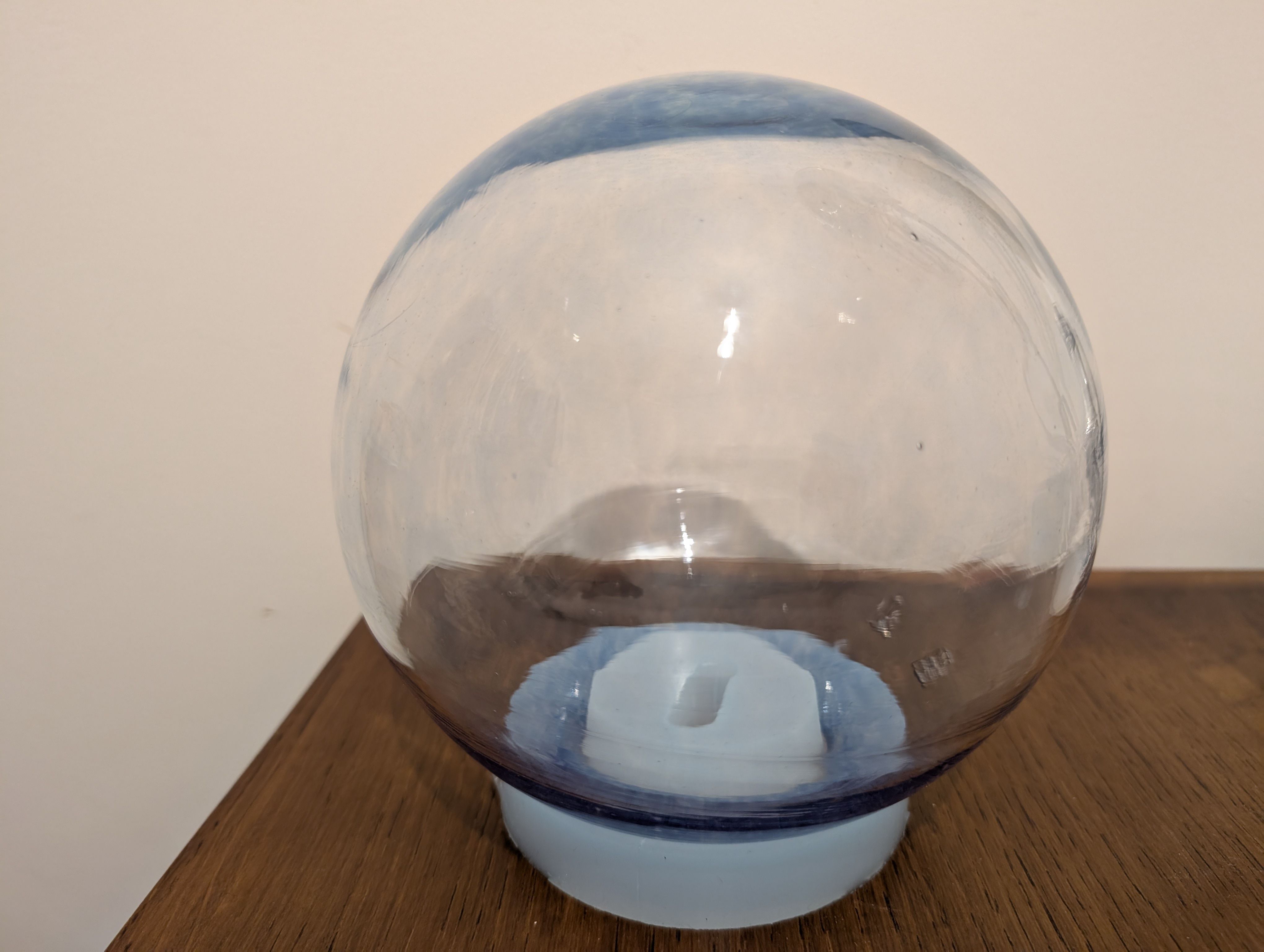
Globe Parts - Glass Blowing
(Visit to a floating ball production studio
in Hokkaido, Japan)
The ball is rotated on a mold and breathed into the mold.
In this case, an
existing mold was used for the sphere, but various shapes are possible
by creating a digital mold.
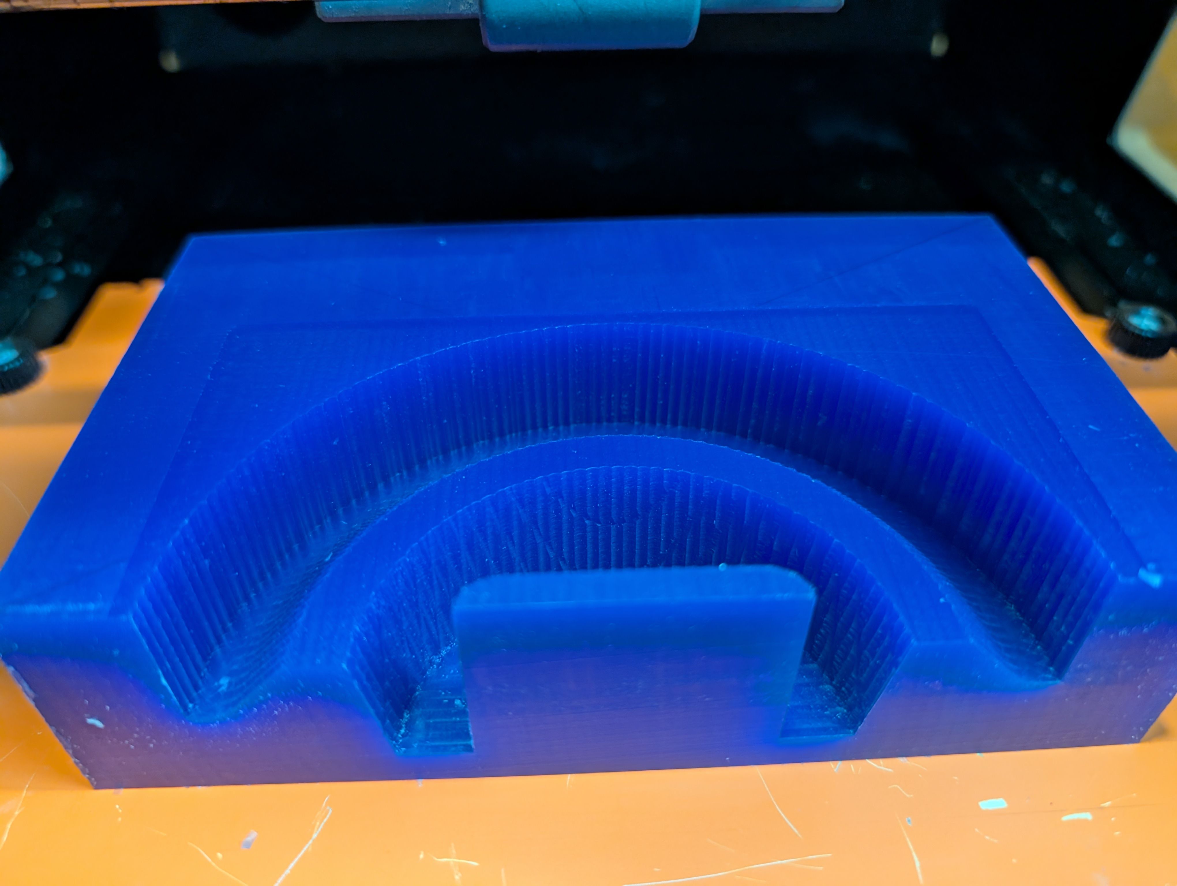
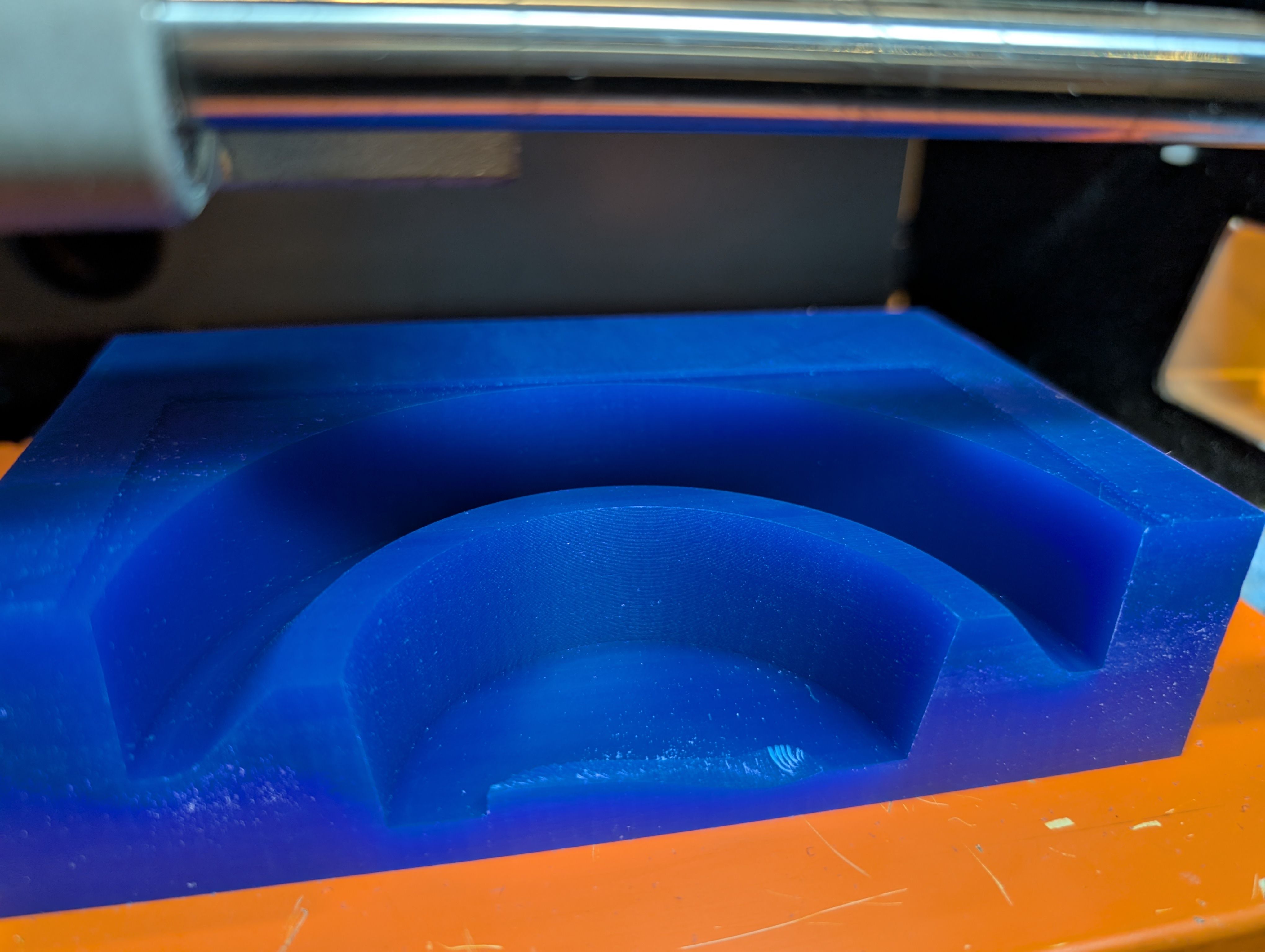
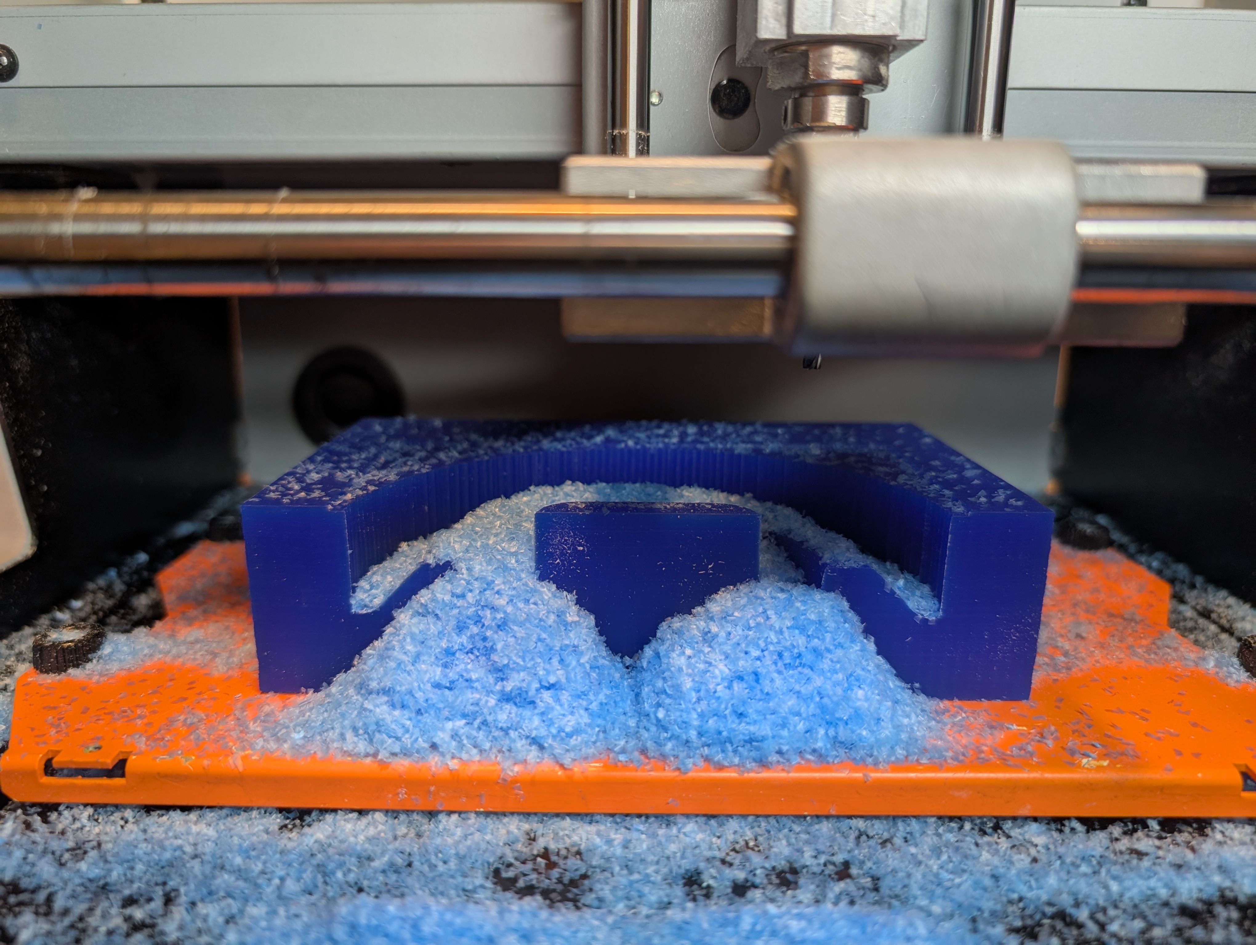
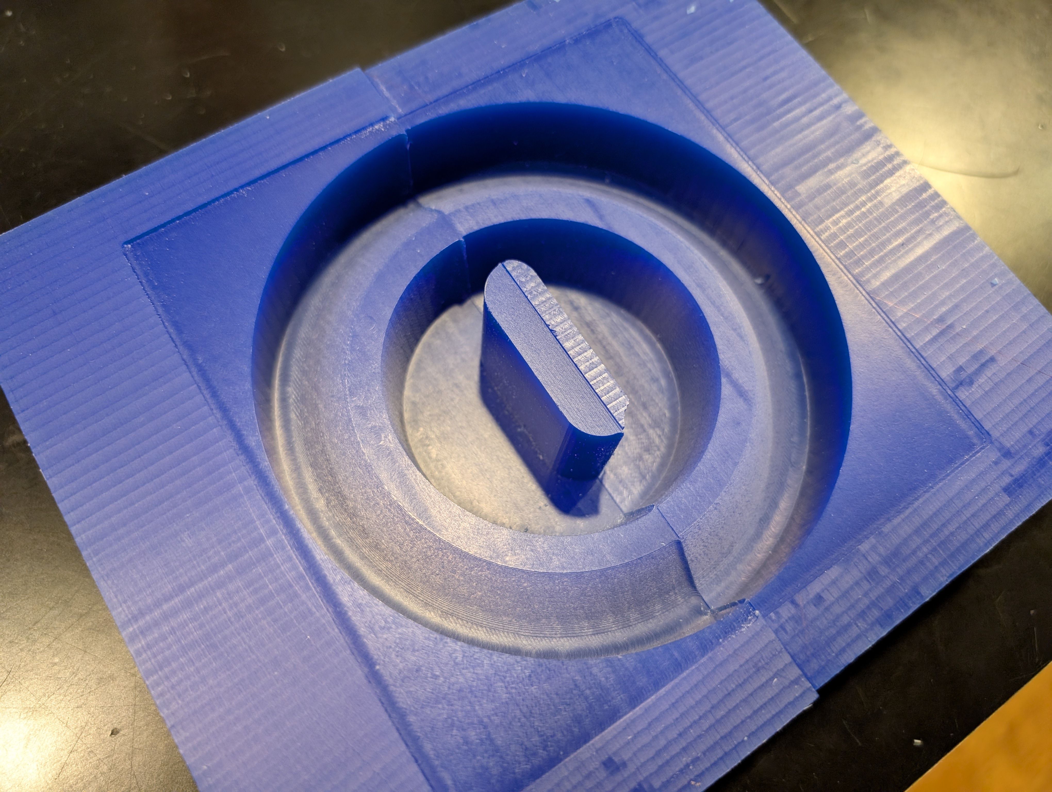
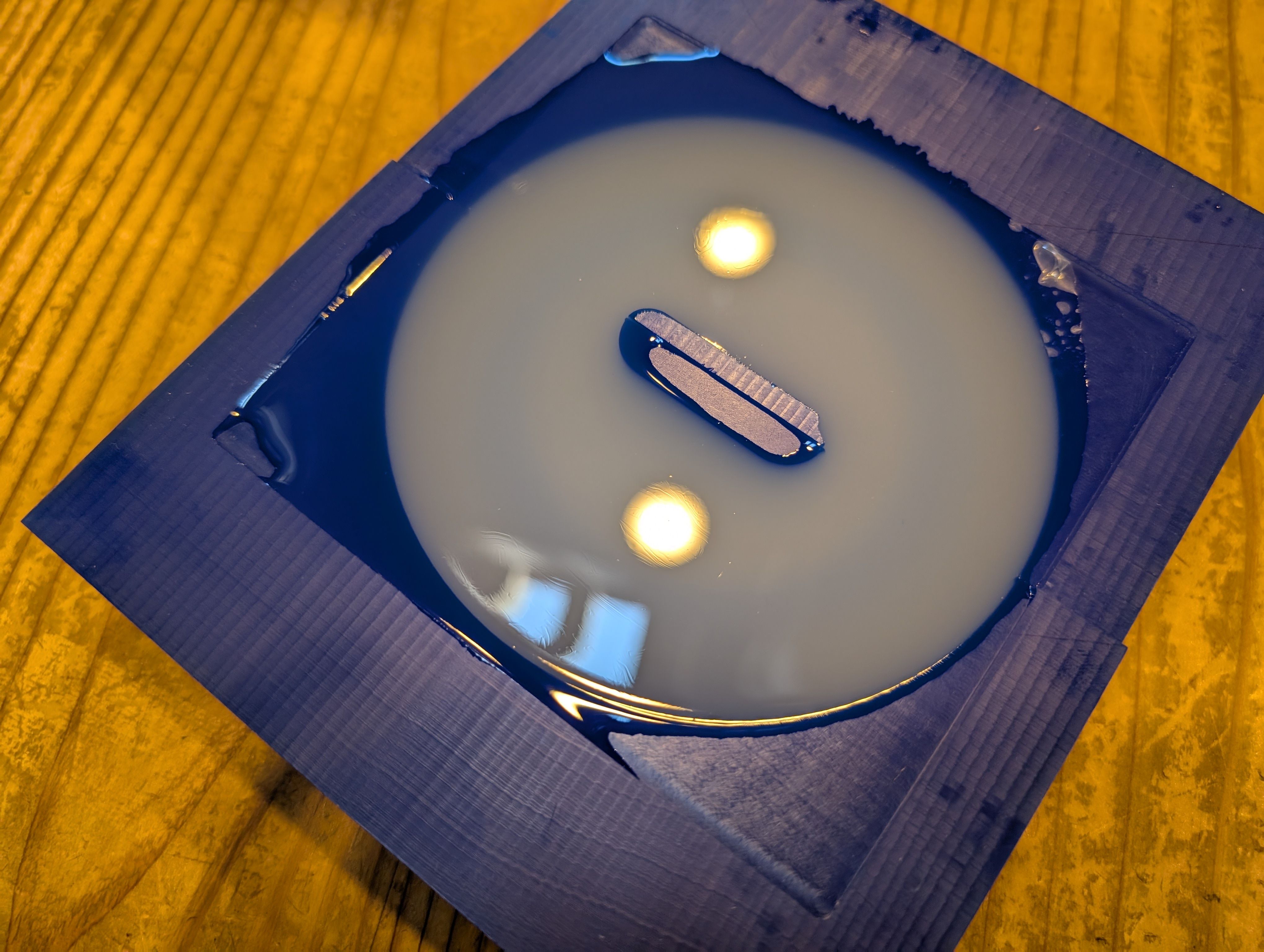
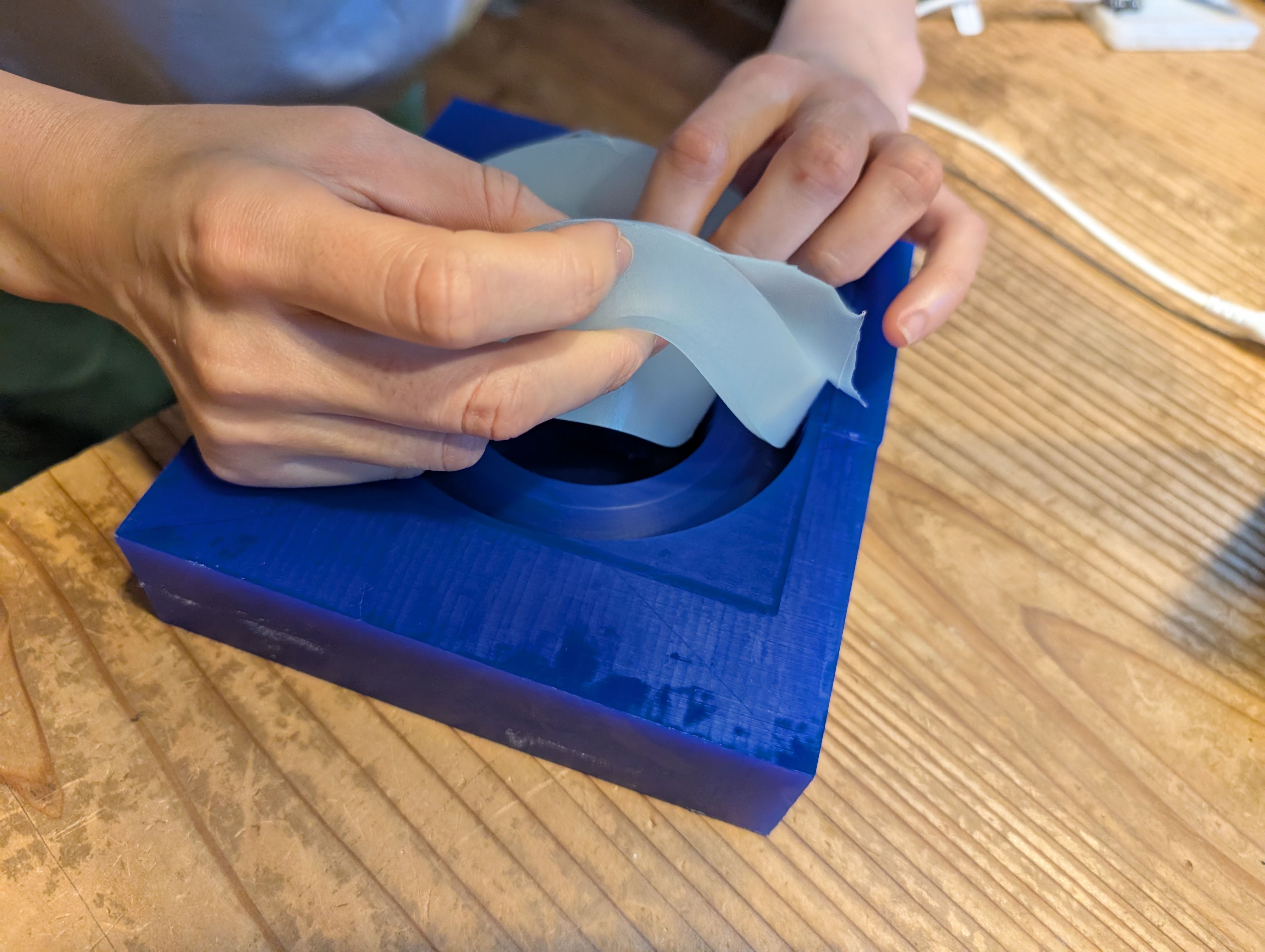
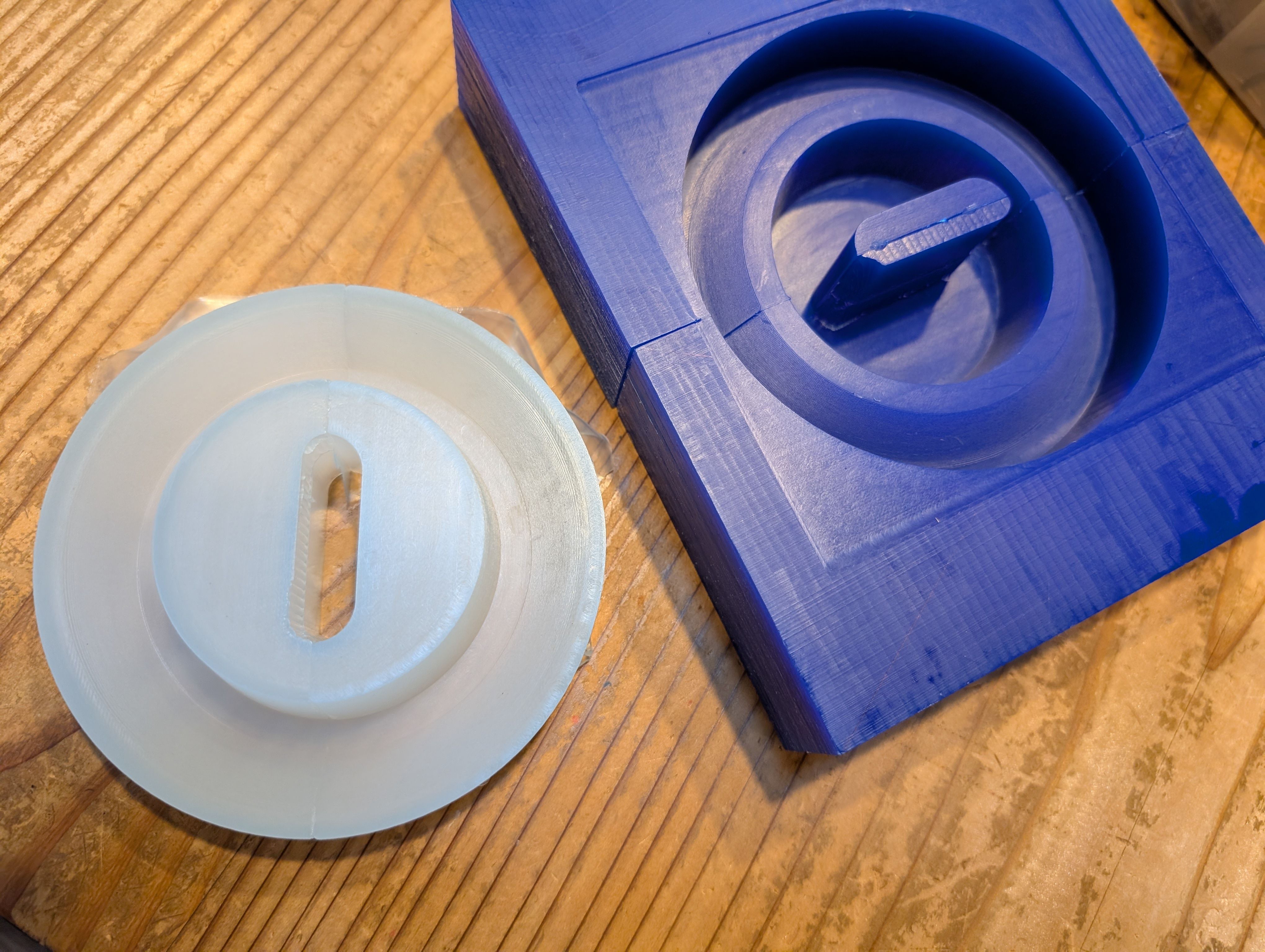
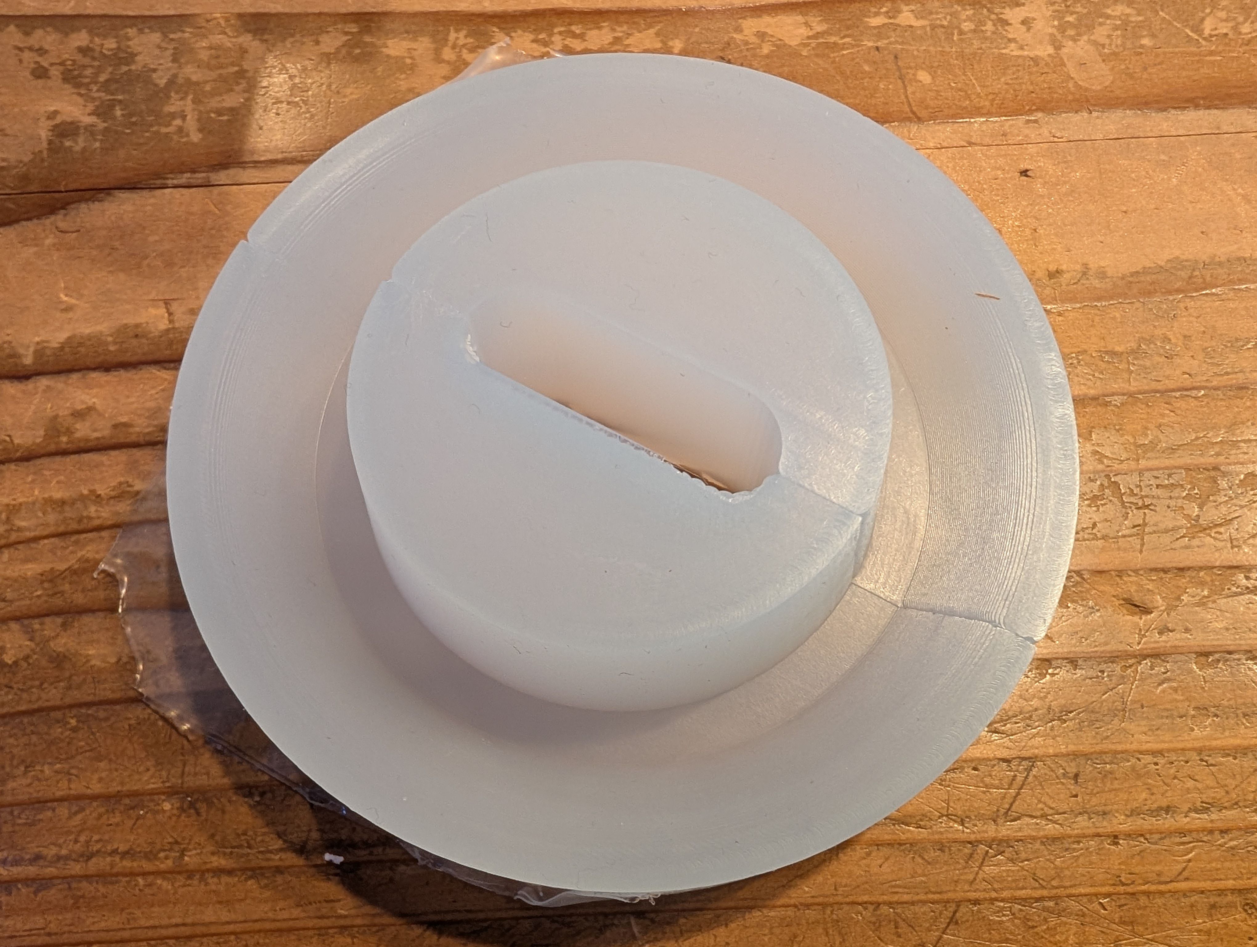
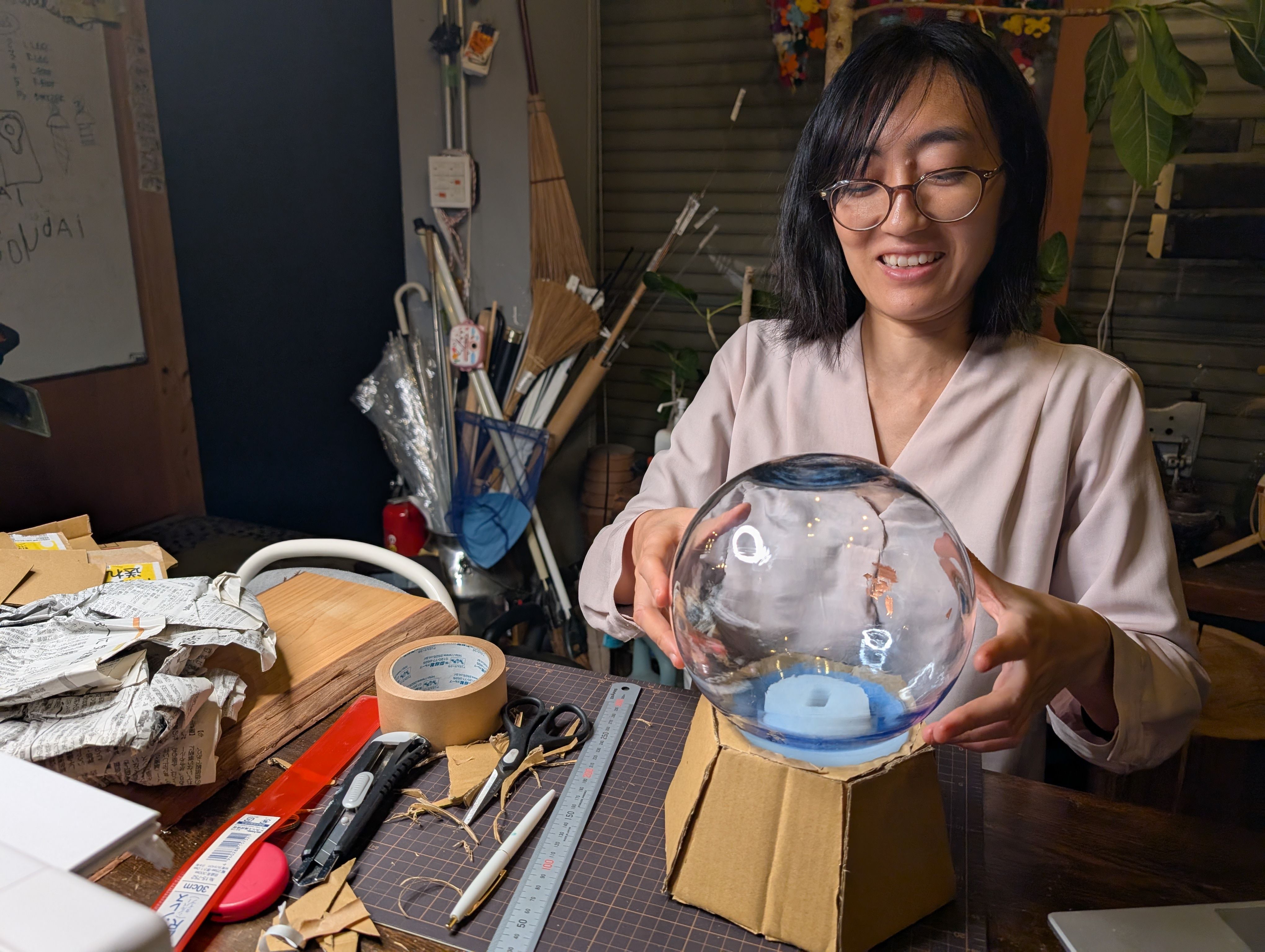
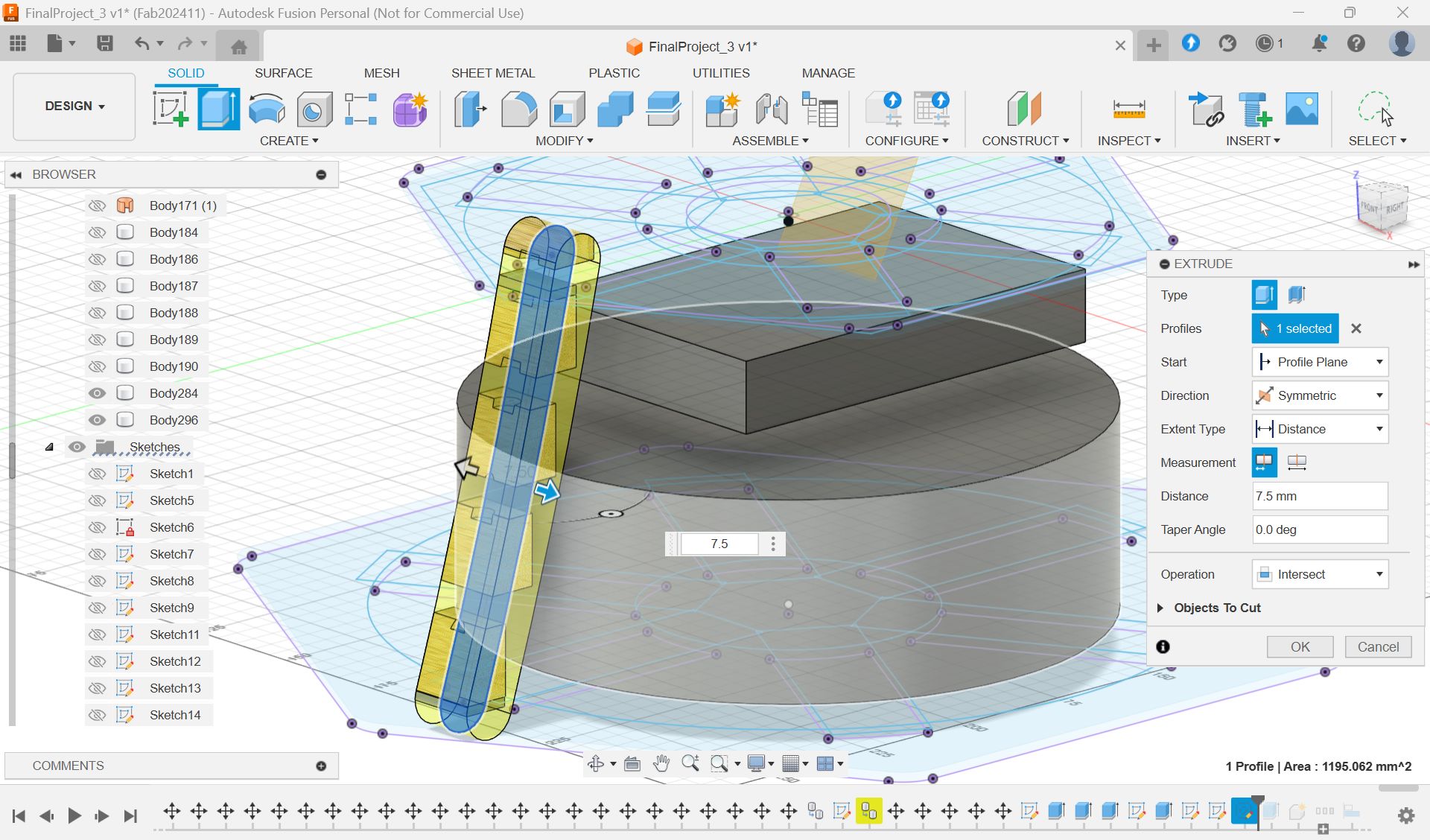
Glass support - Molding and Casting(Week 13)
In week 13, I try to make base parts for the glass globe.
It would be nise if this support part is soft enough to protect the glass. So I
wanted to use silicon.
*My first plan was float the globe, but it seems no time to do it for 1st spiral…So
this new part is needed.
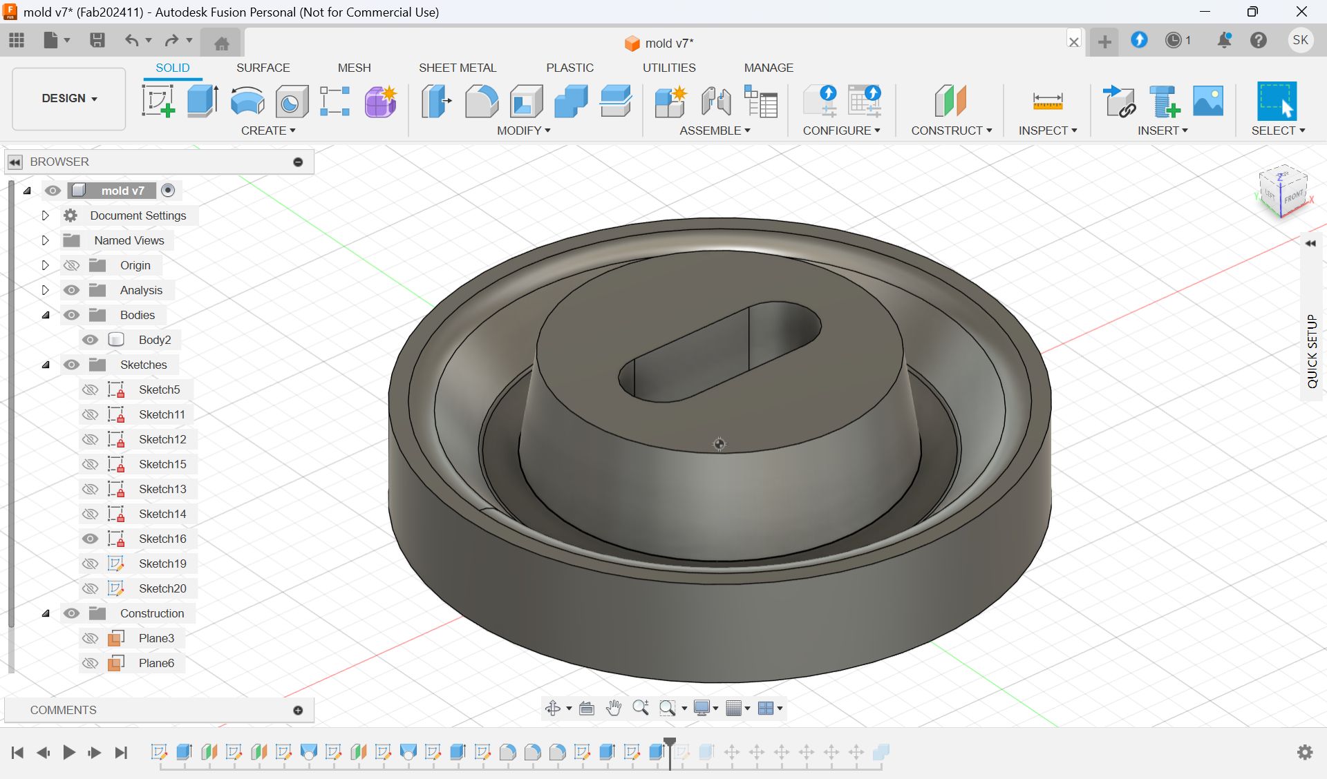
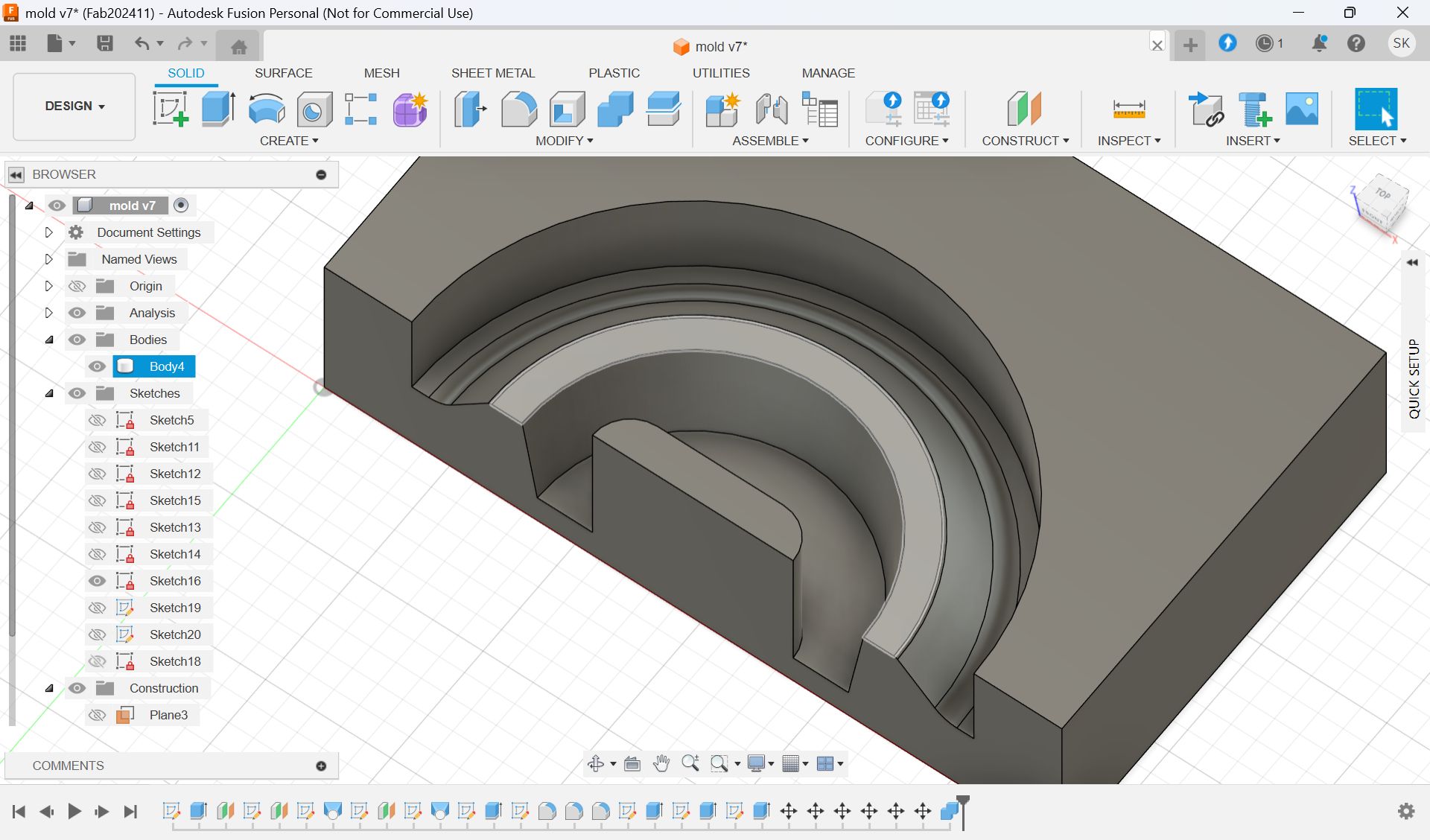
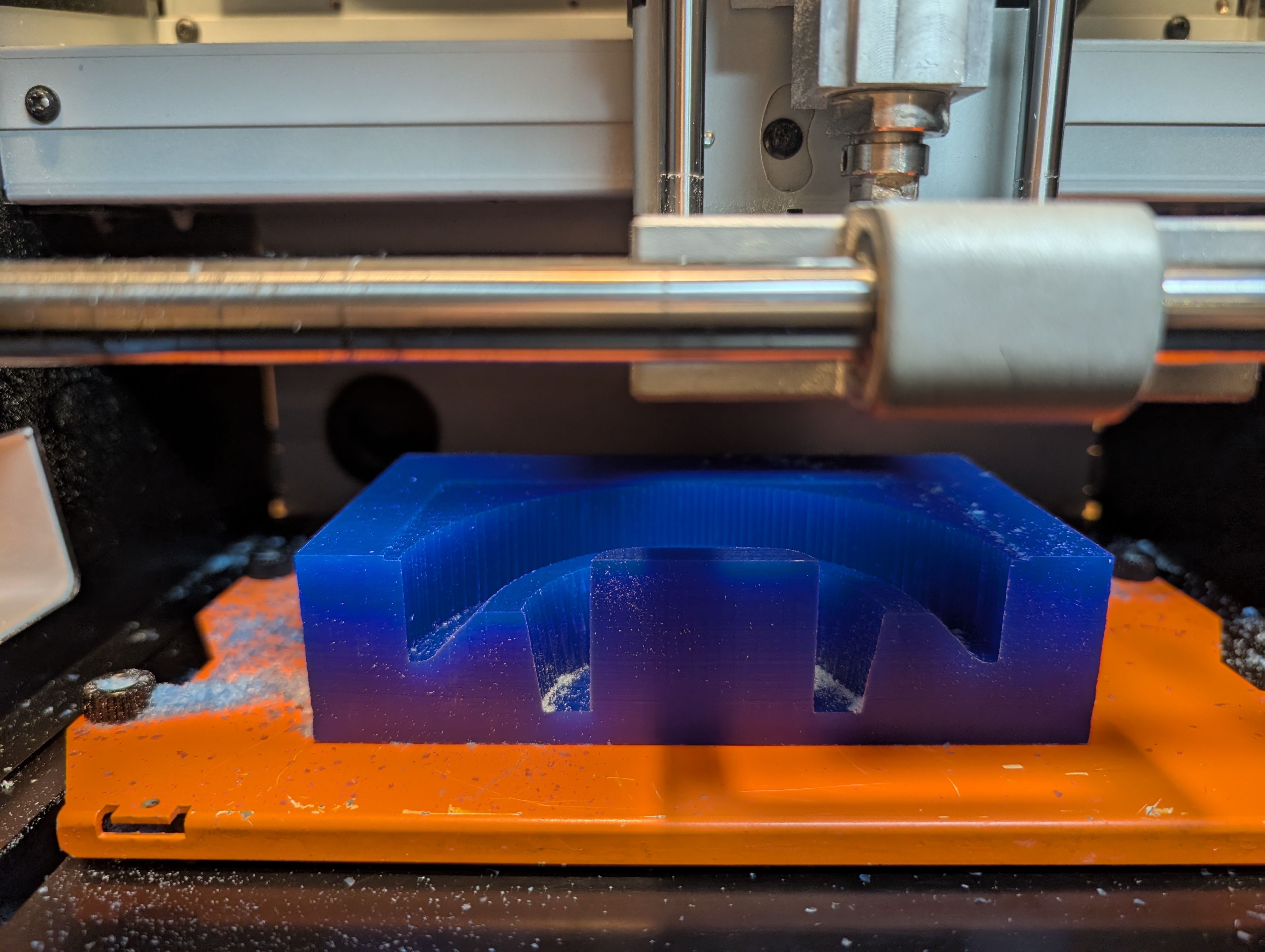
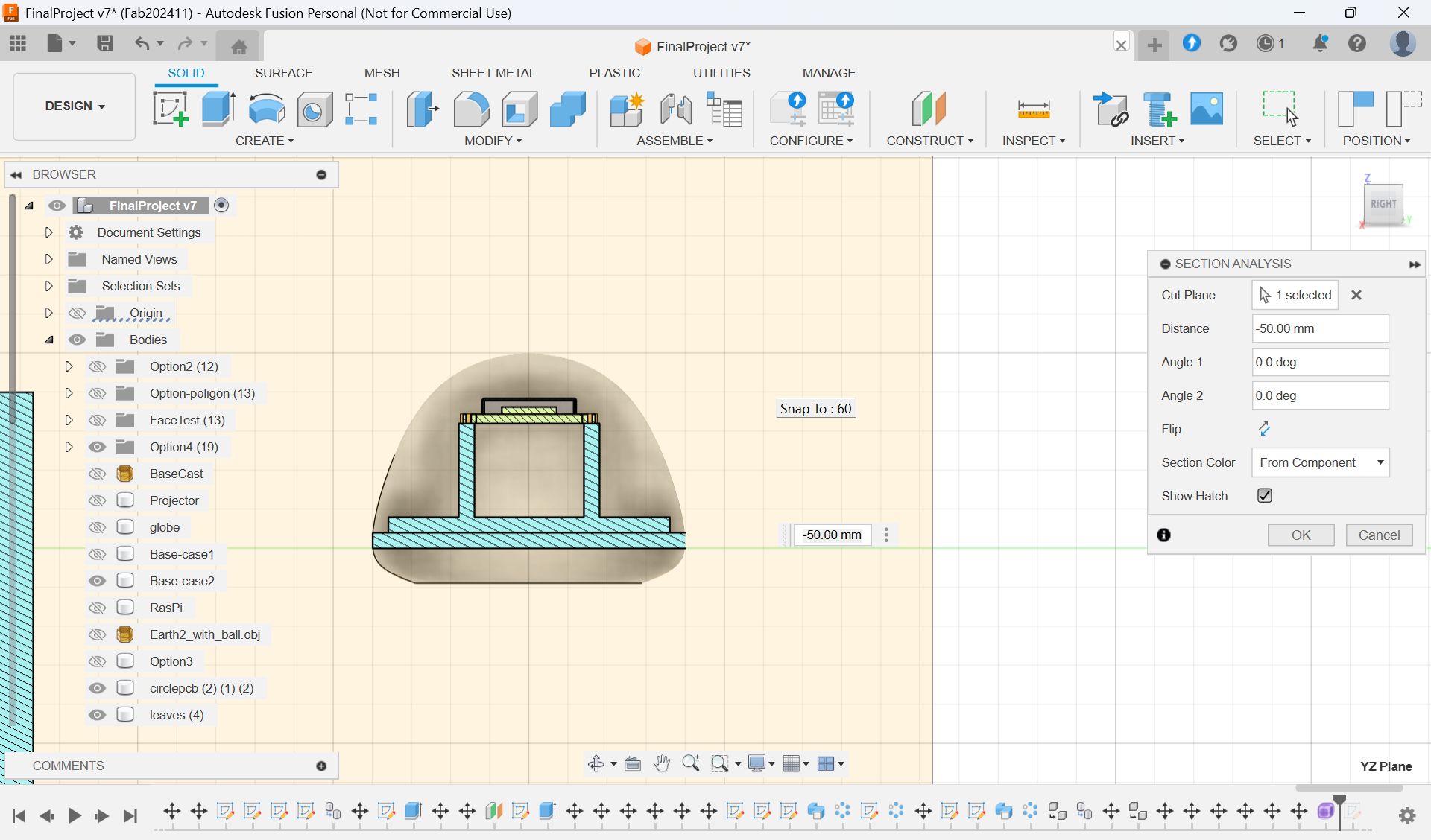
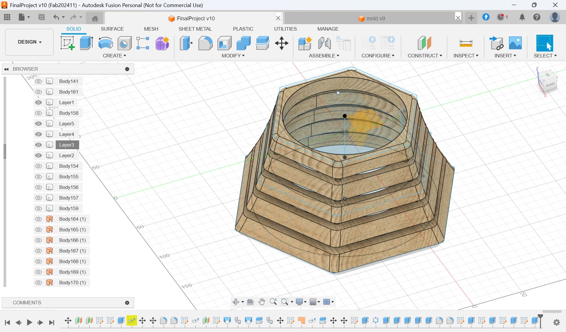
Modeling - Fusion
I scaled the glass and decide the number
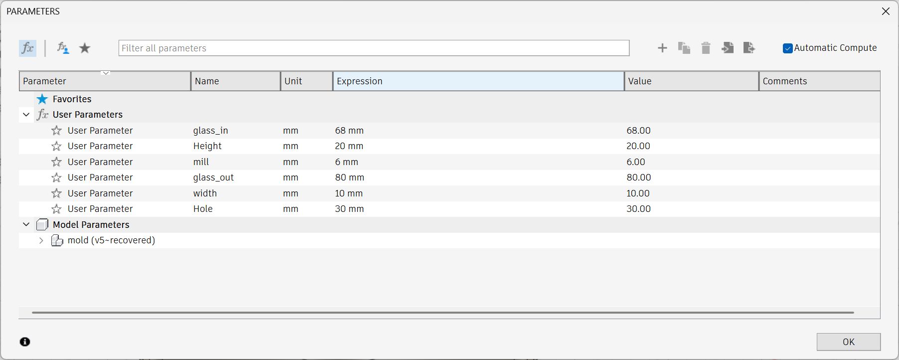
Parameter for final model
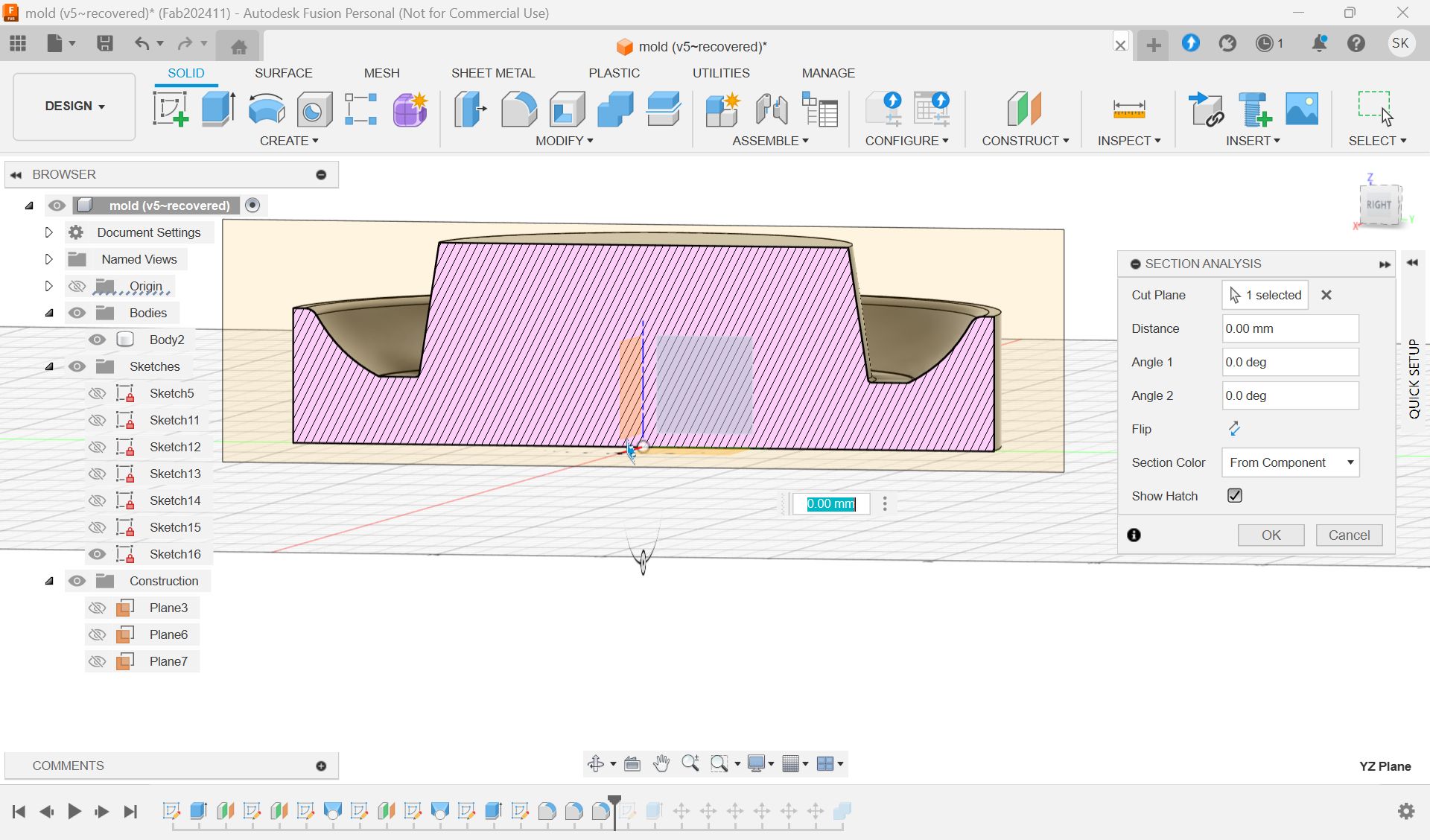
Check the cross section
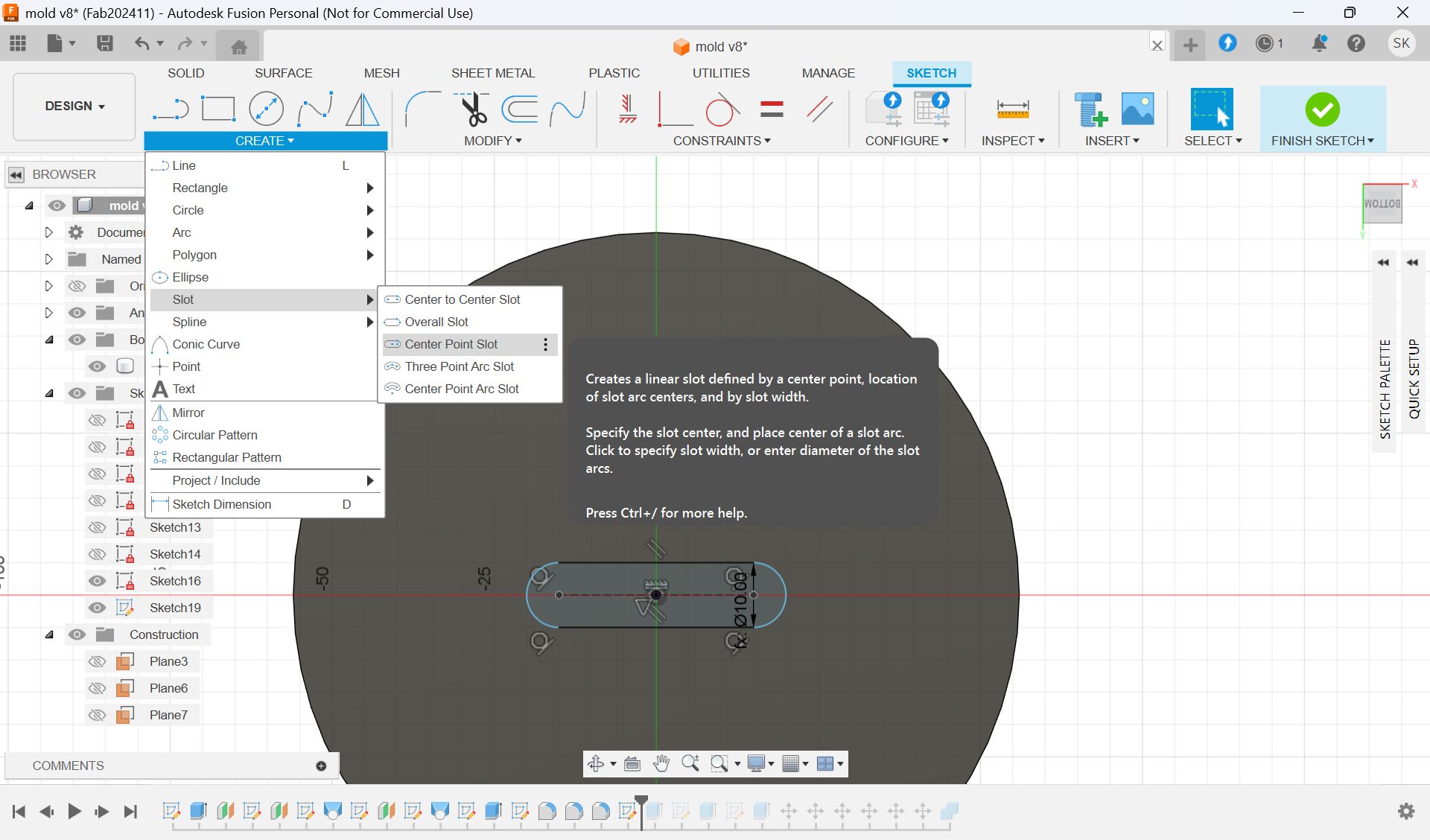
I wanted to add a hole for cables.
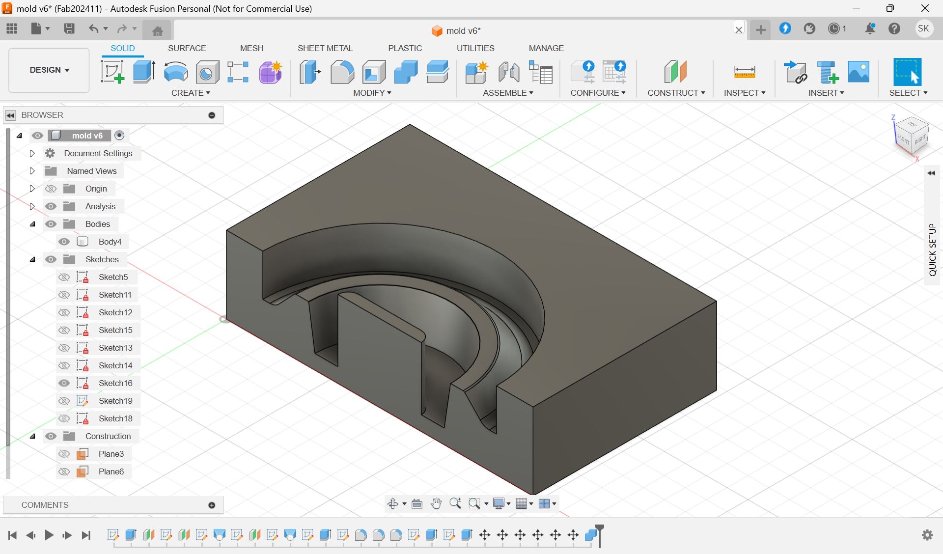
Add hole with “Slot“ form Sketch menu and extrude it.
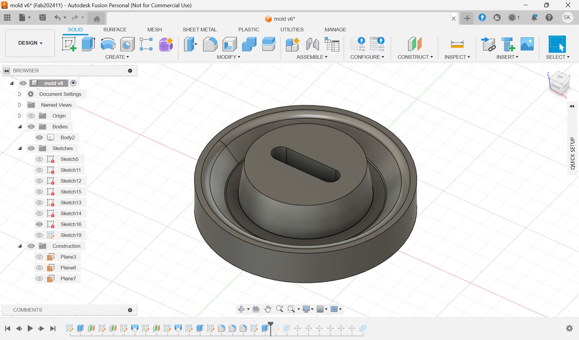
Since the wax is smaller than the model size, I made the half cut mold.
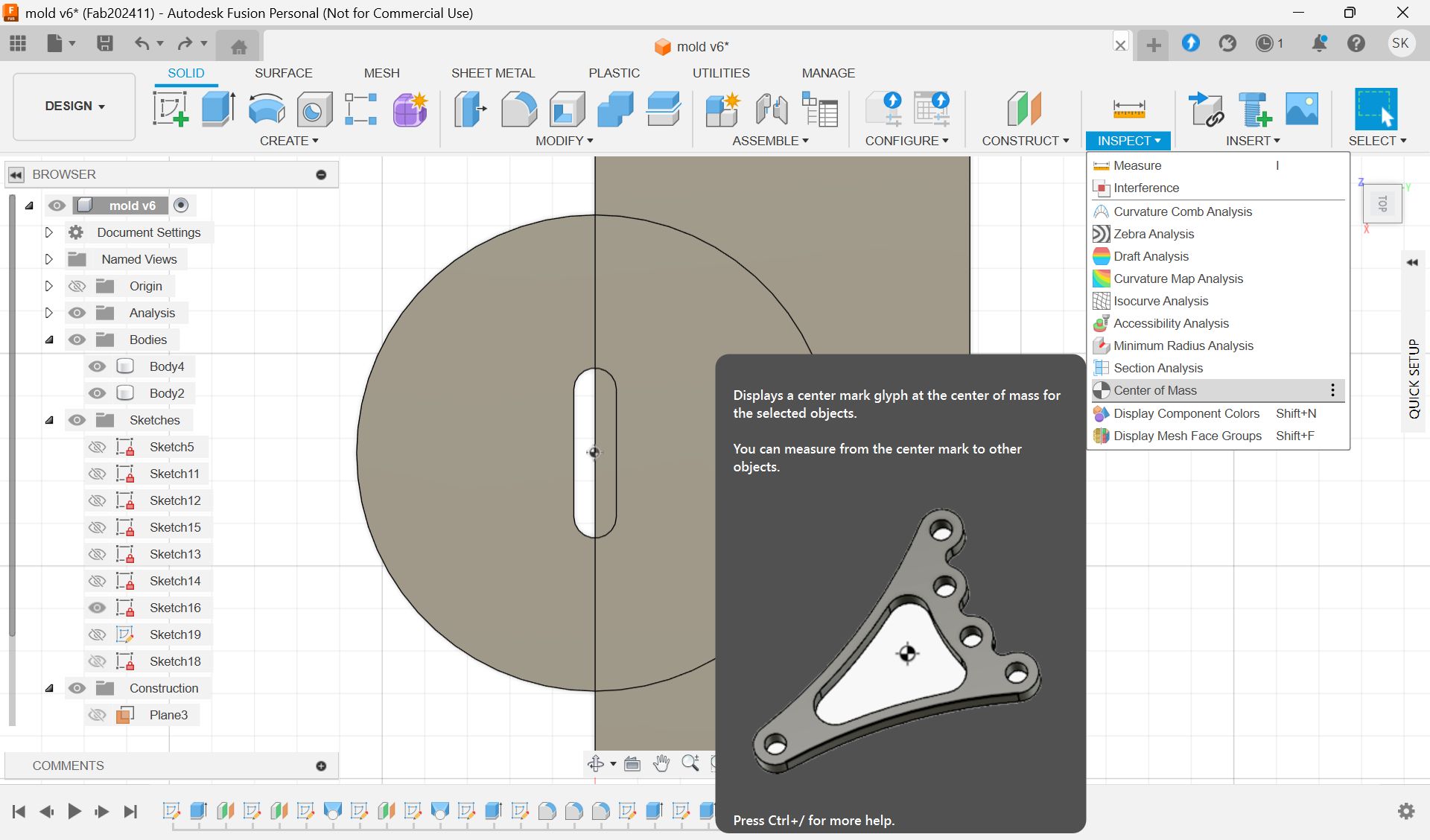
To make it divided in the center, use the “Center of mass”.
This is the final model for 1st half.
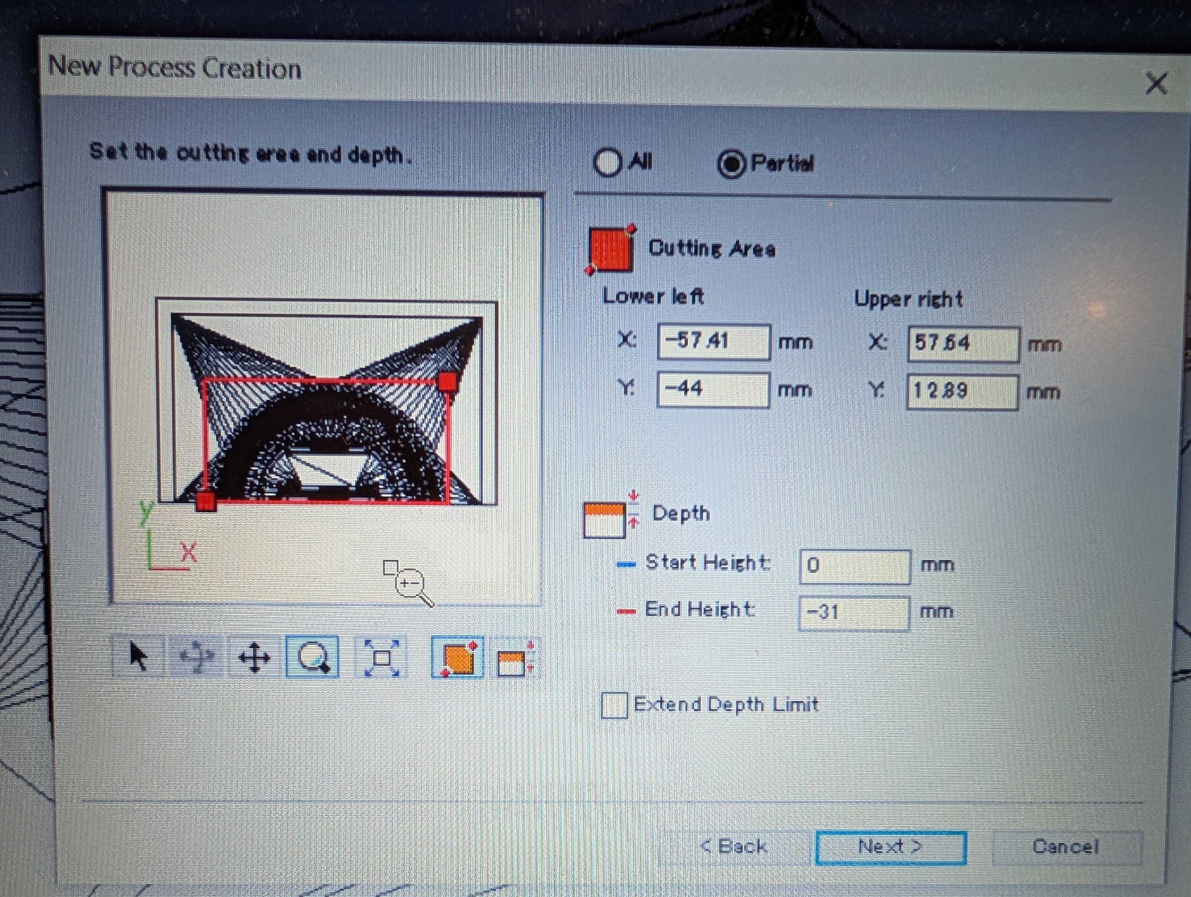
Path
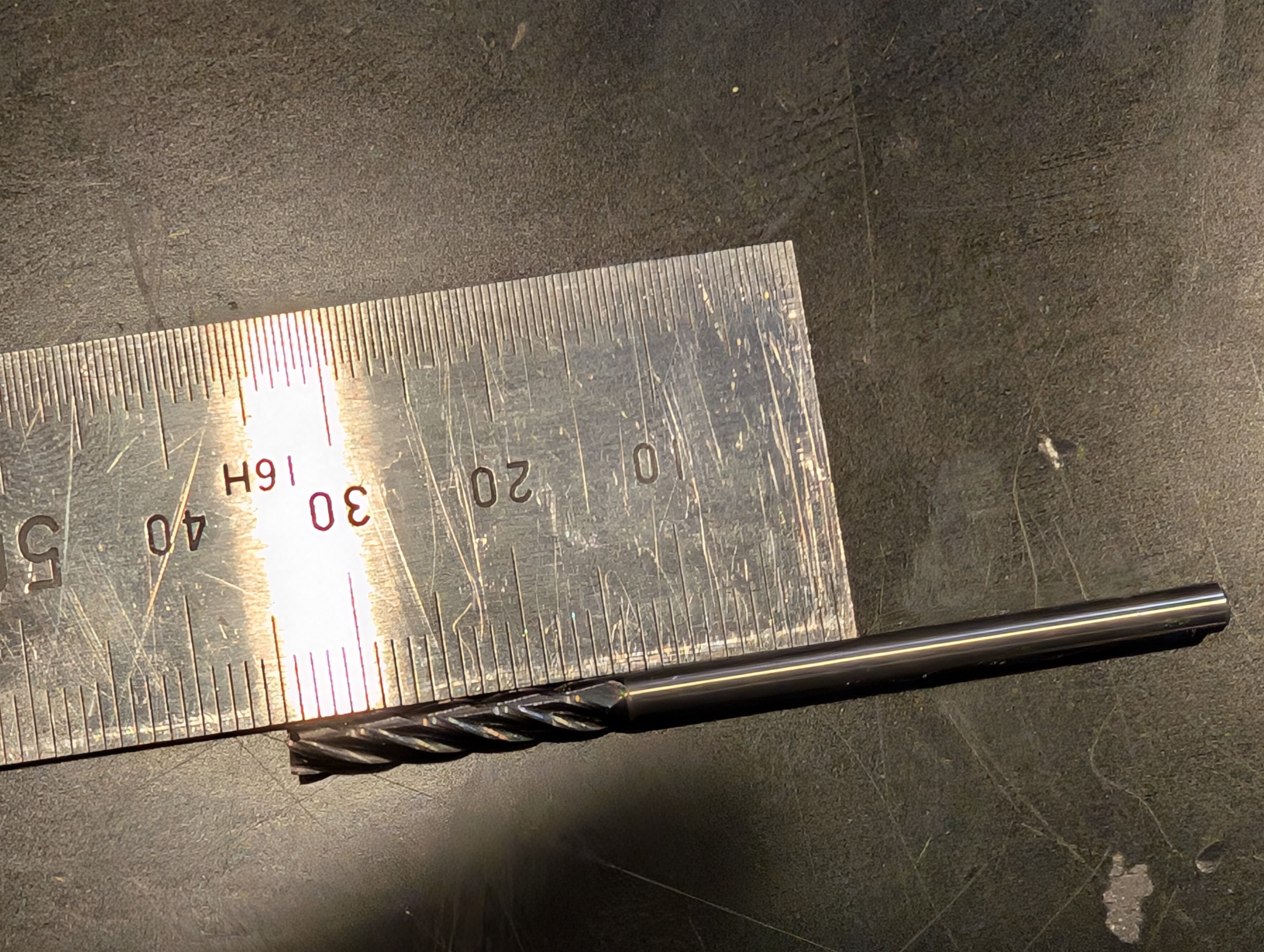
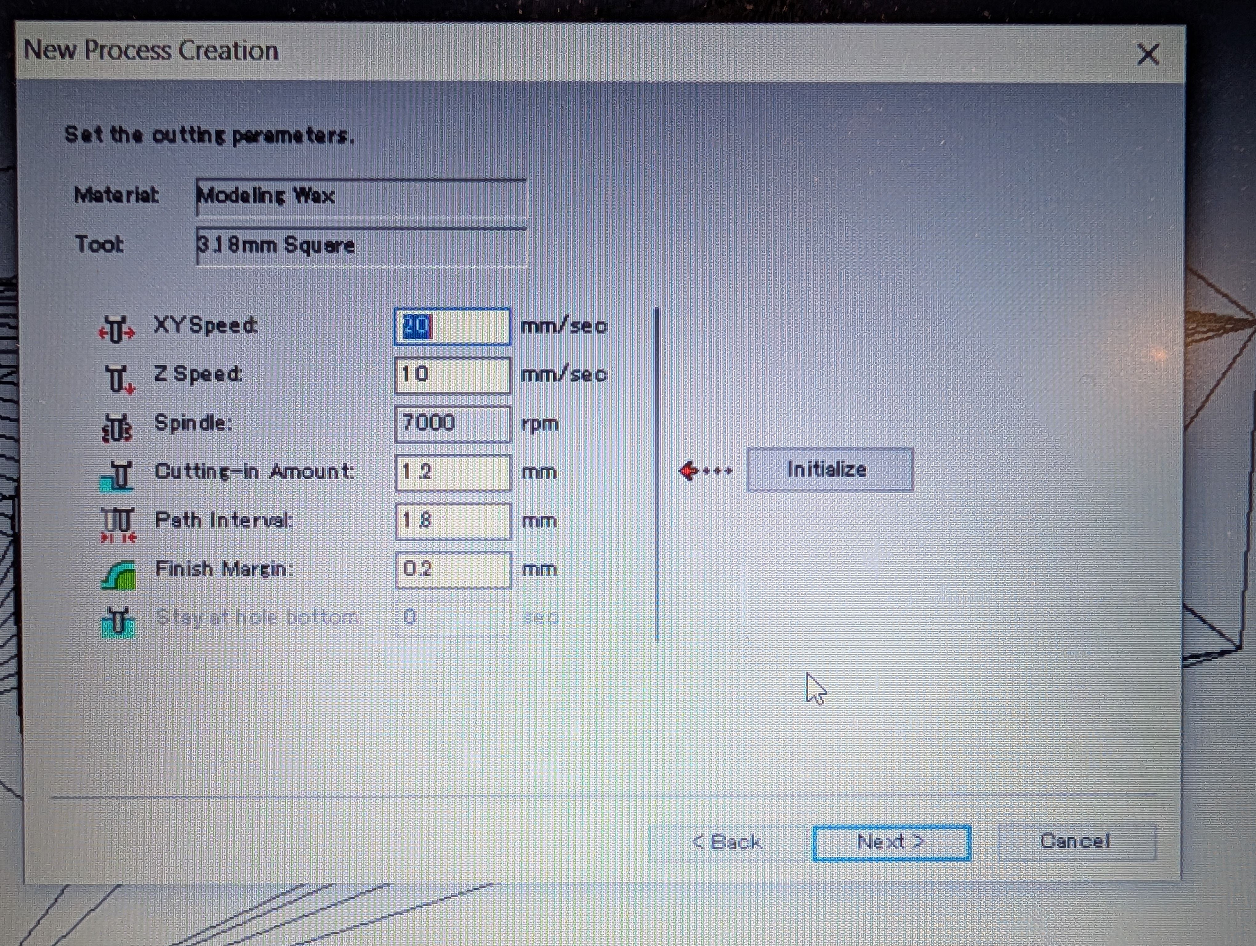
This time I alse chosed 3.18 square mill.
Setting for roughing
Scan Lines = X + Y
XY speed = 20 mm/sec
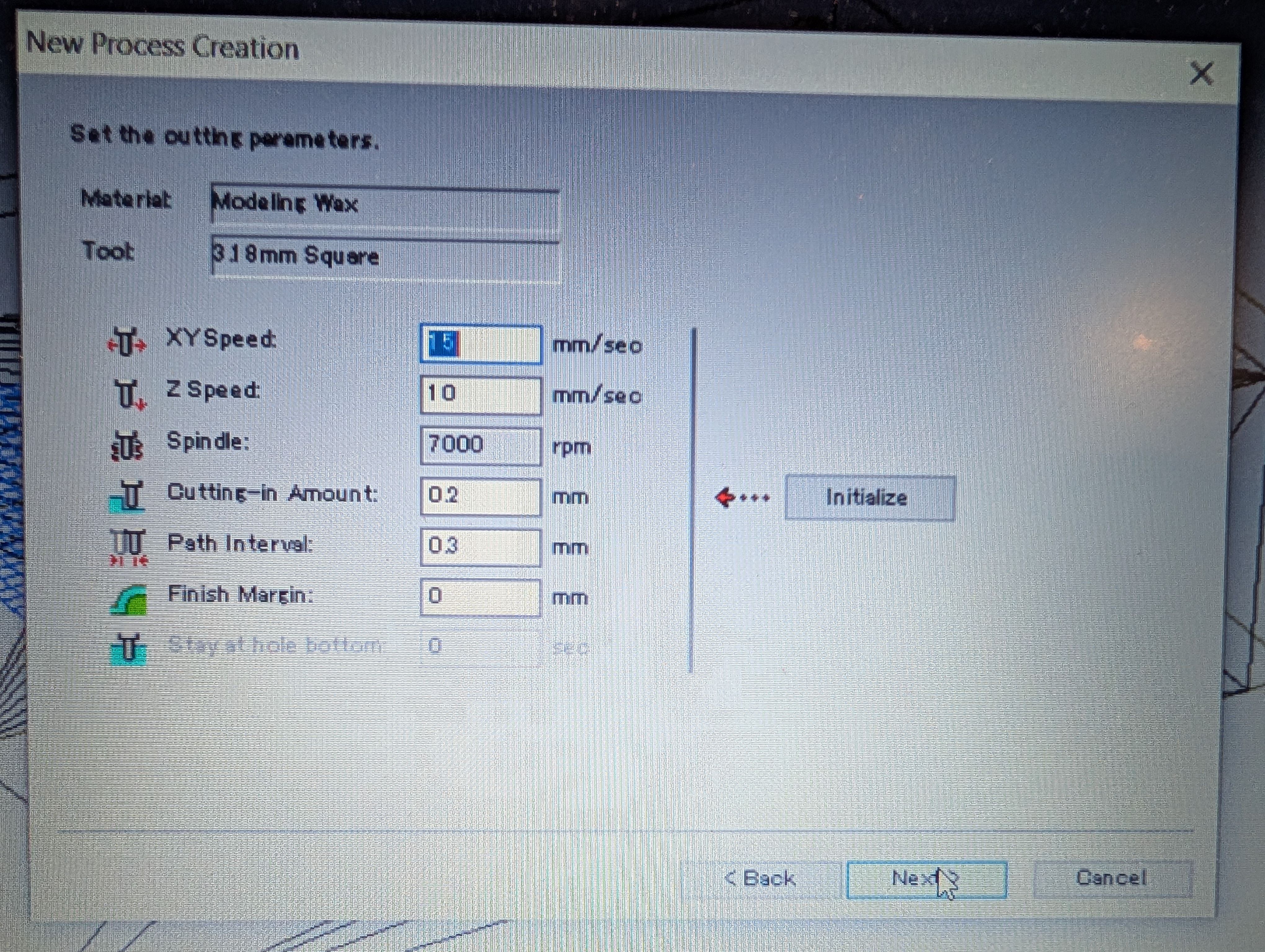
Setting for Finishing
Contour Lines : Up out
XY speed = 15 mm/sec
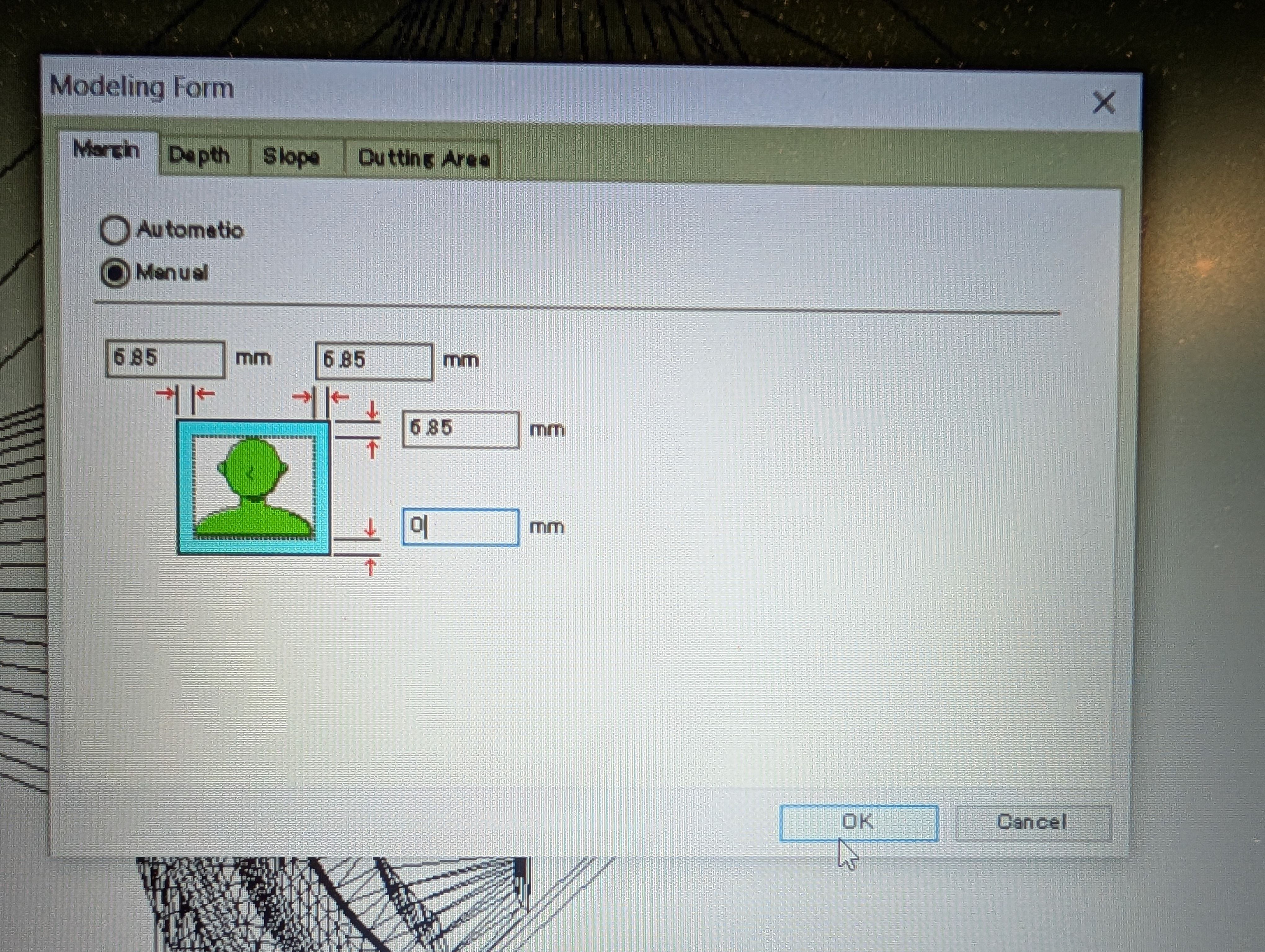
To will without leaving any edges, I have to delete margin.
I set margin bottom = 0mm from Modeling Form menu.
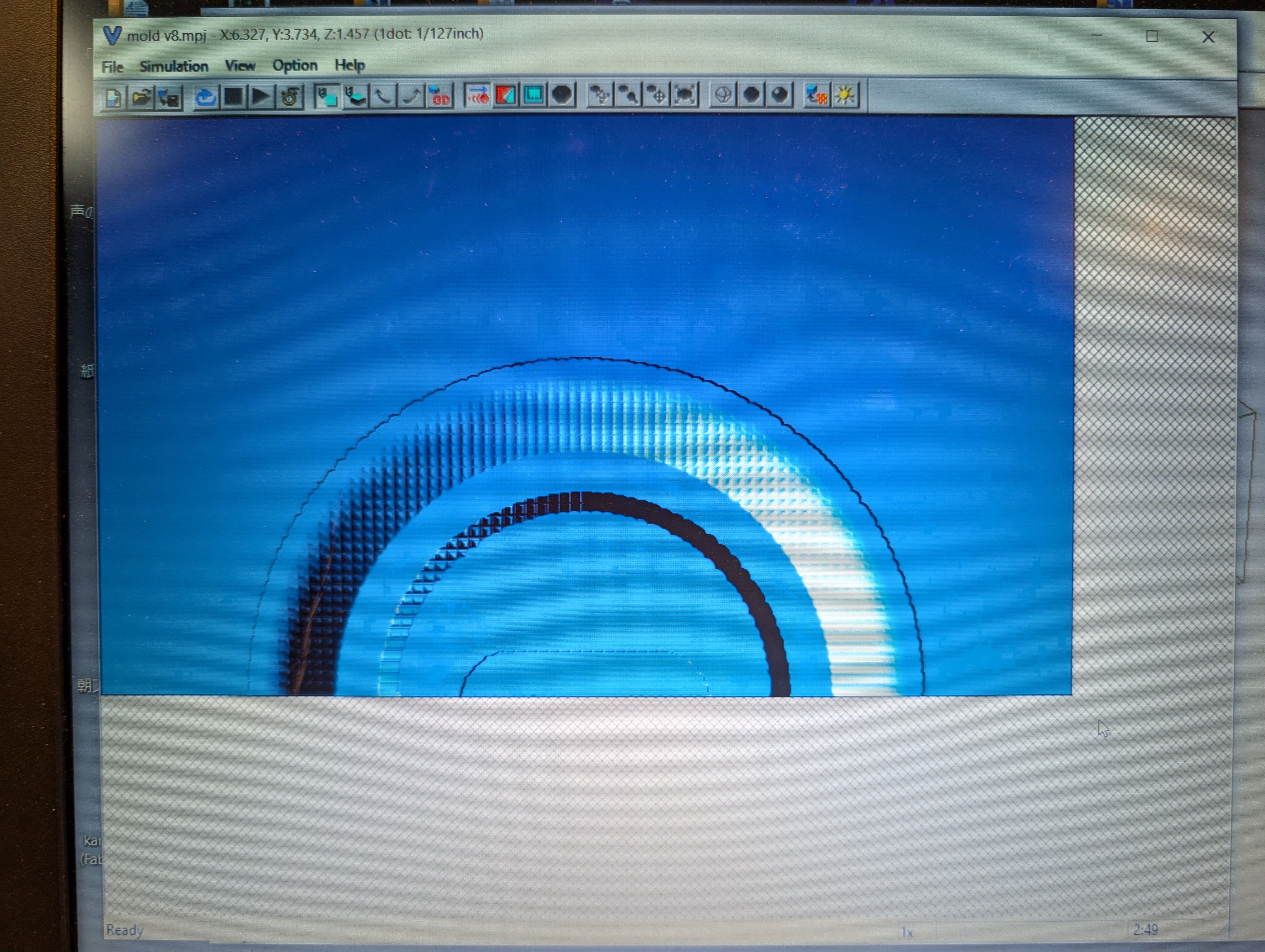
Check time from “Preview Cutting” menu
Time for roughing: 2:53
Time for finishing: 1:37
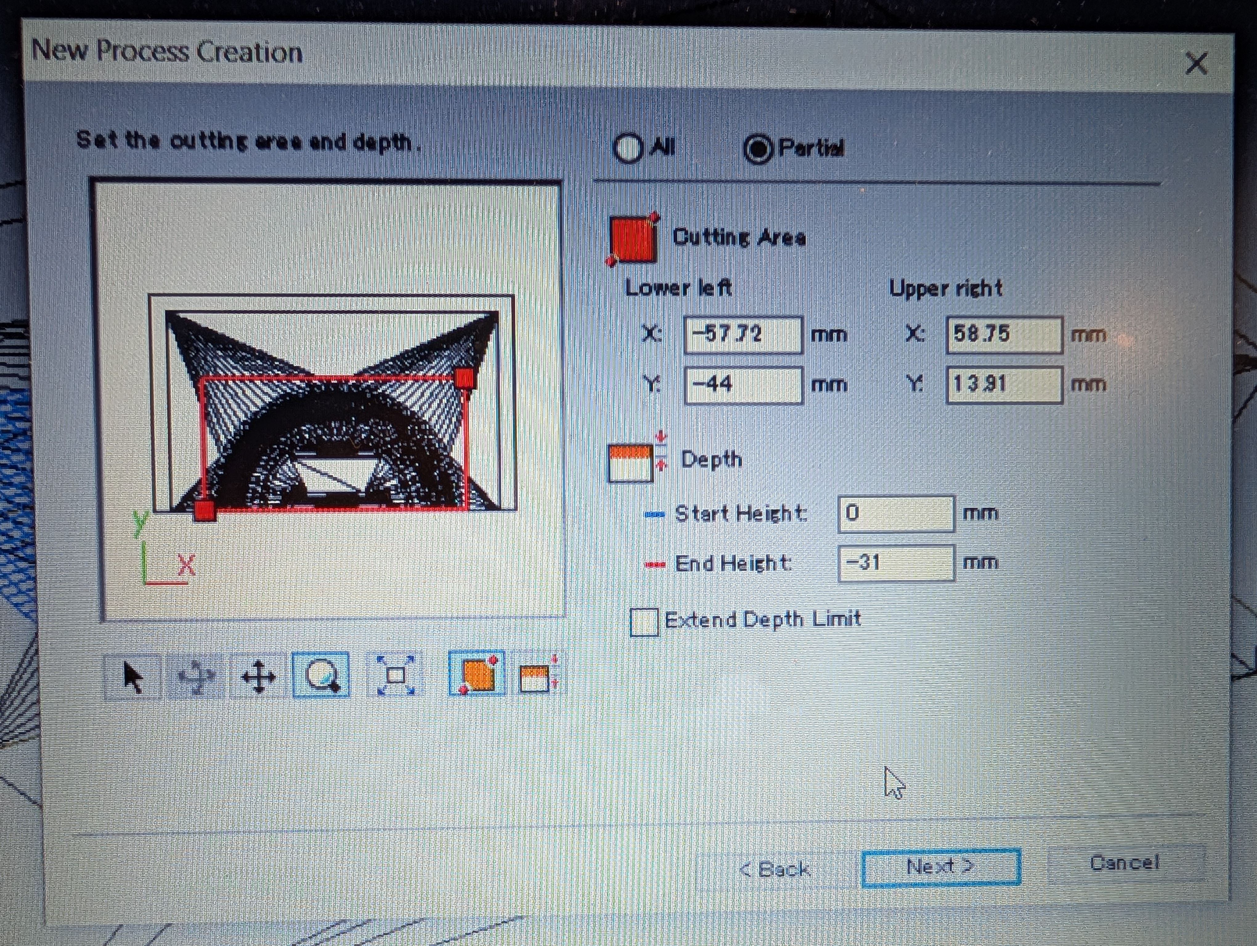
To set tool, I have to check the depth of workspace, and height of wax, and
calculate
depth of workspace : 31mm
(depth of design: 30mm)
height of wax: 37mm
→tool length should be between 31-37
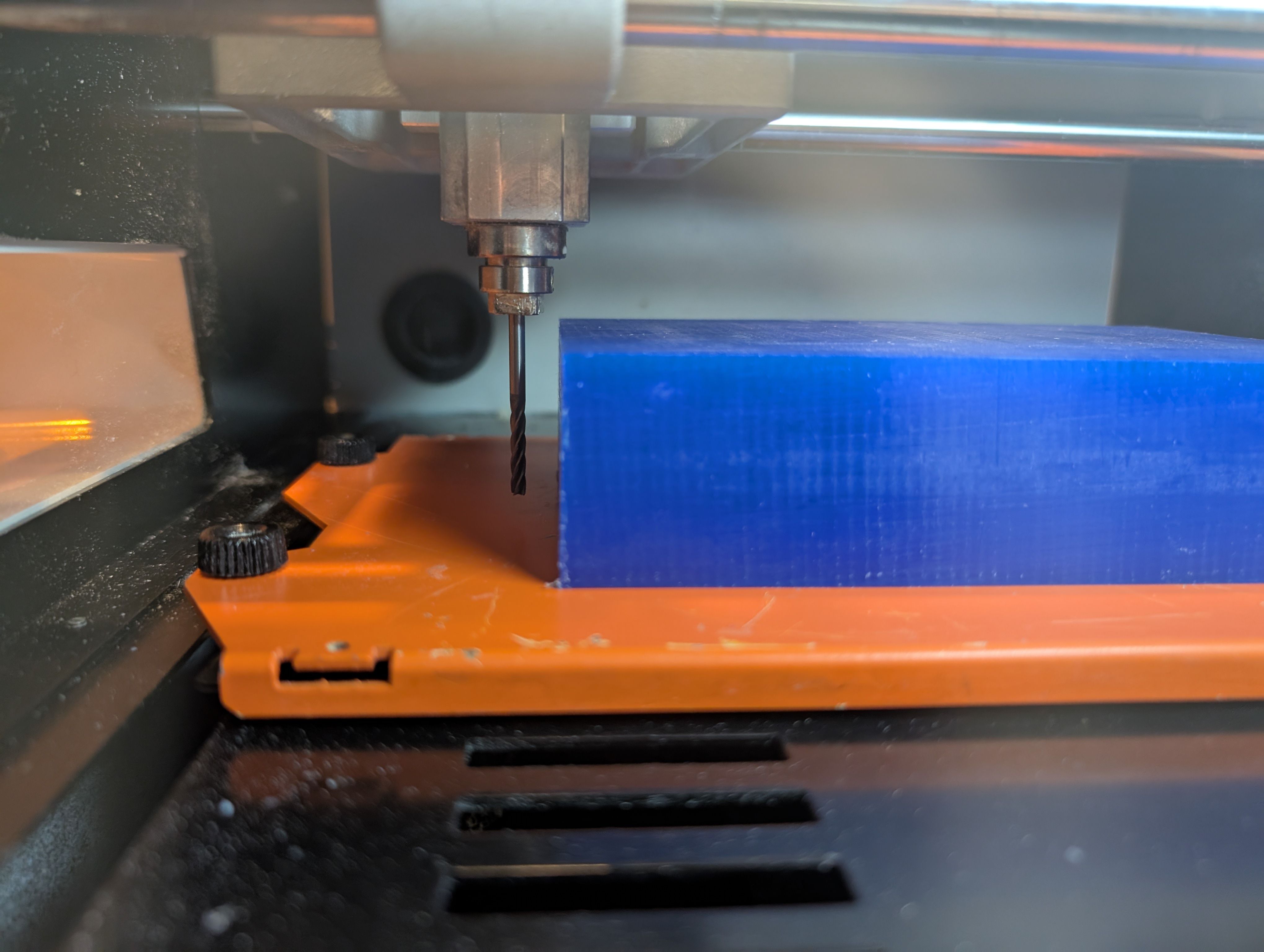
Start cutting.
Roughing goes well.
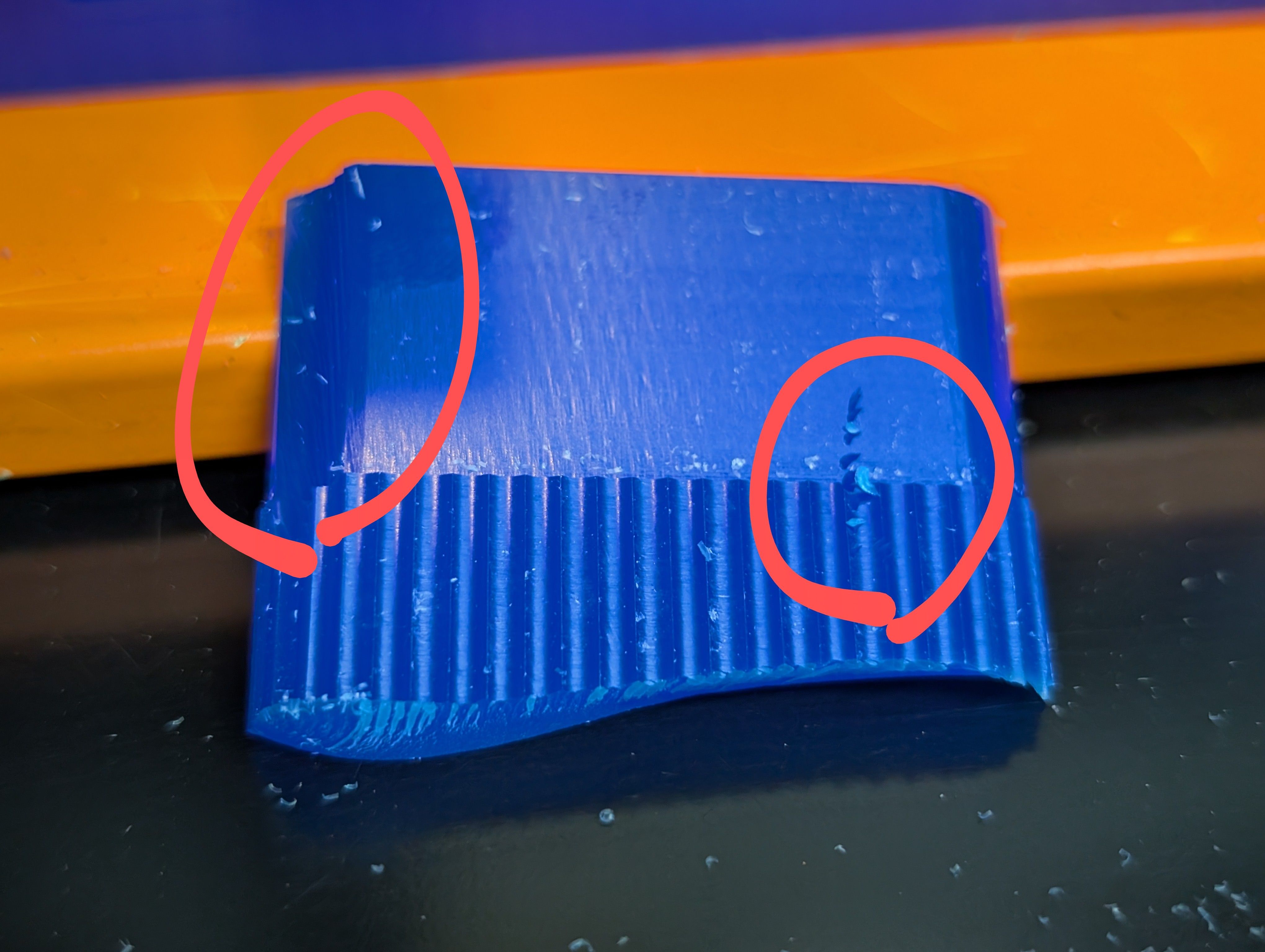
Finisinng
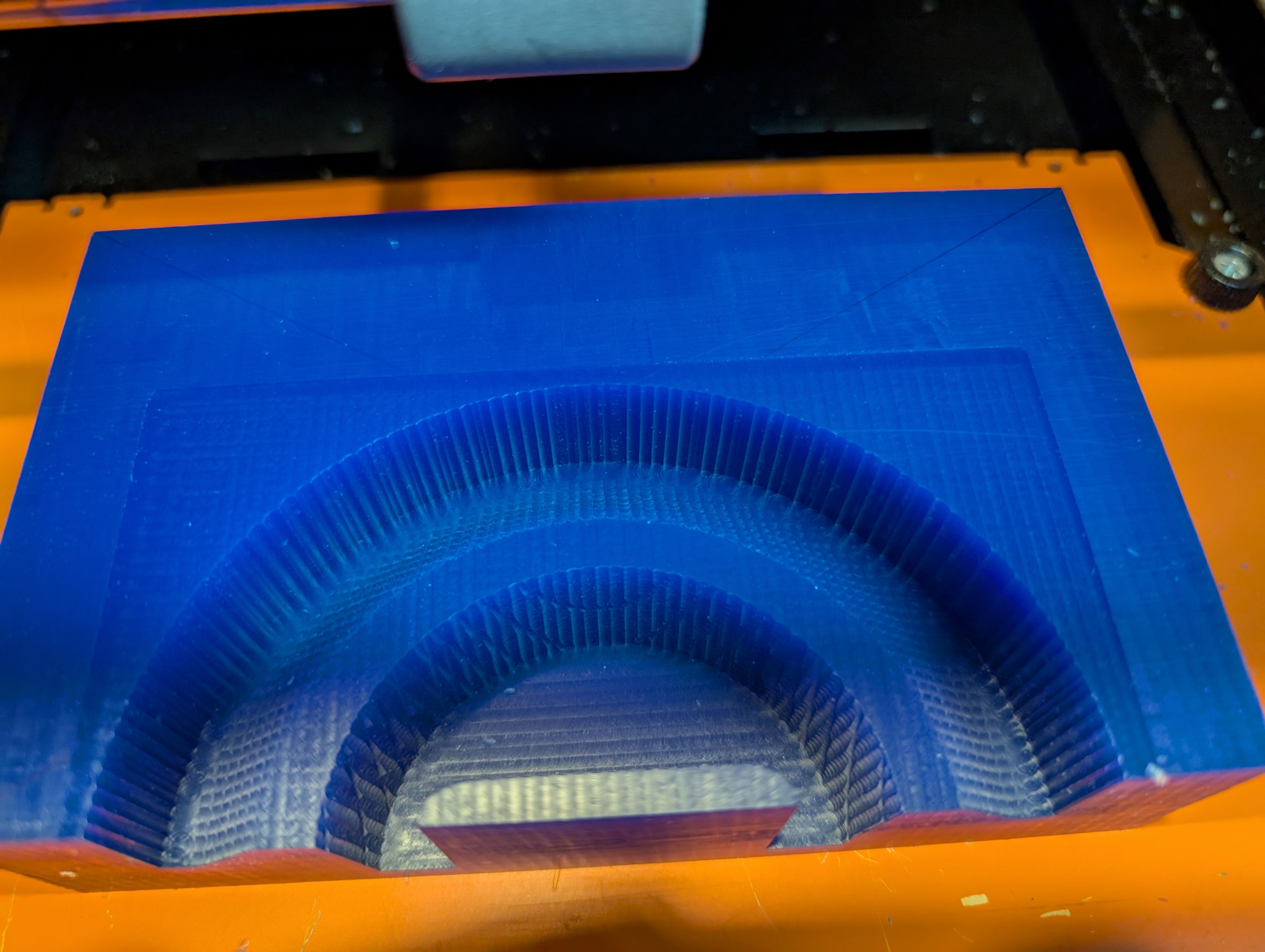
However, while finishing, the wall broken…(for make hole)
It seems the width is too thin.
Since the mill blades go in from the same direction every time, I think too much
pressure was being
applied in that direction only.
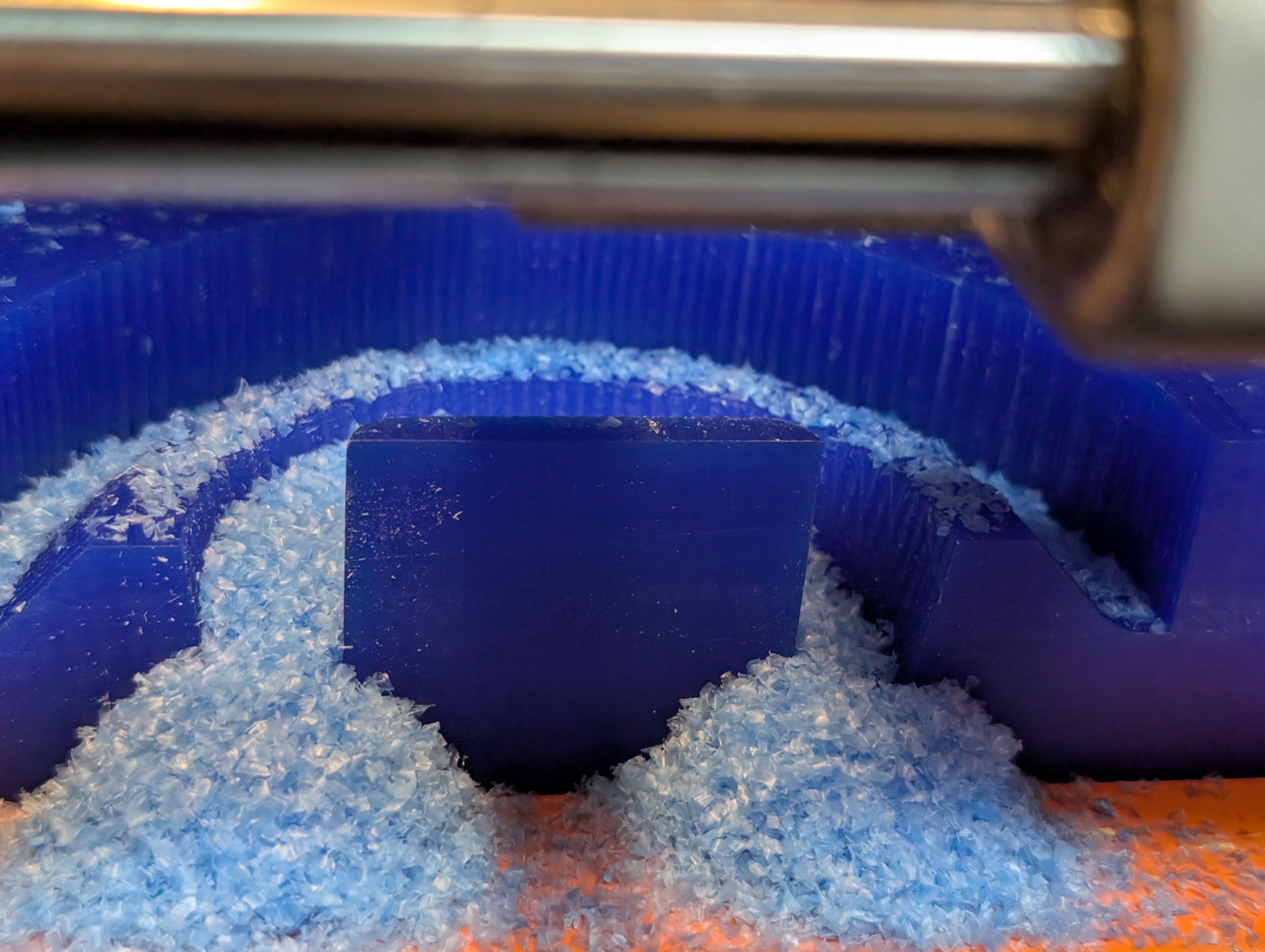
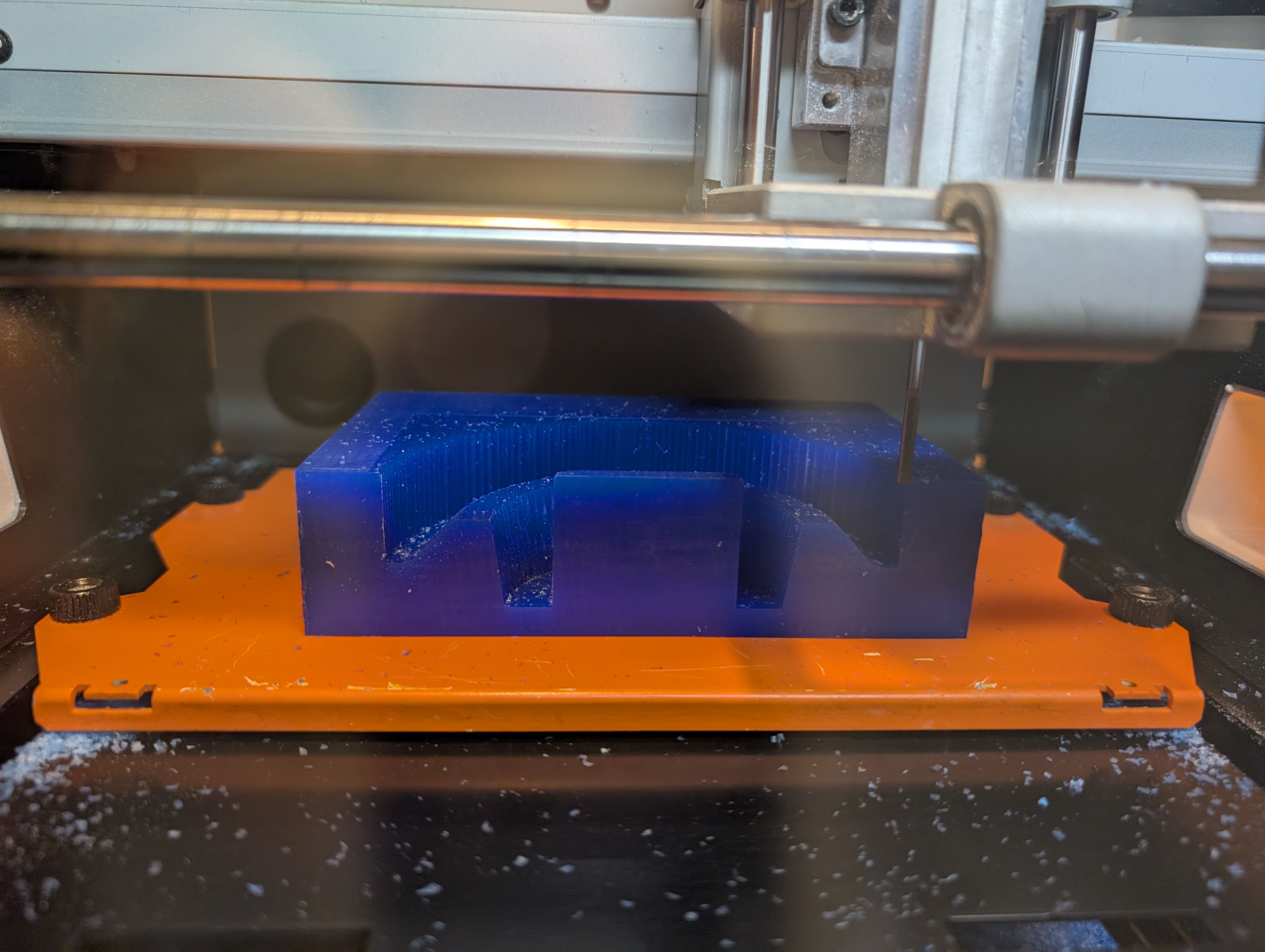
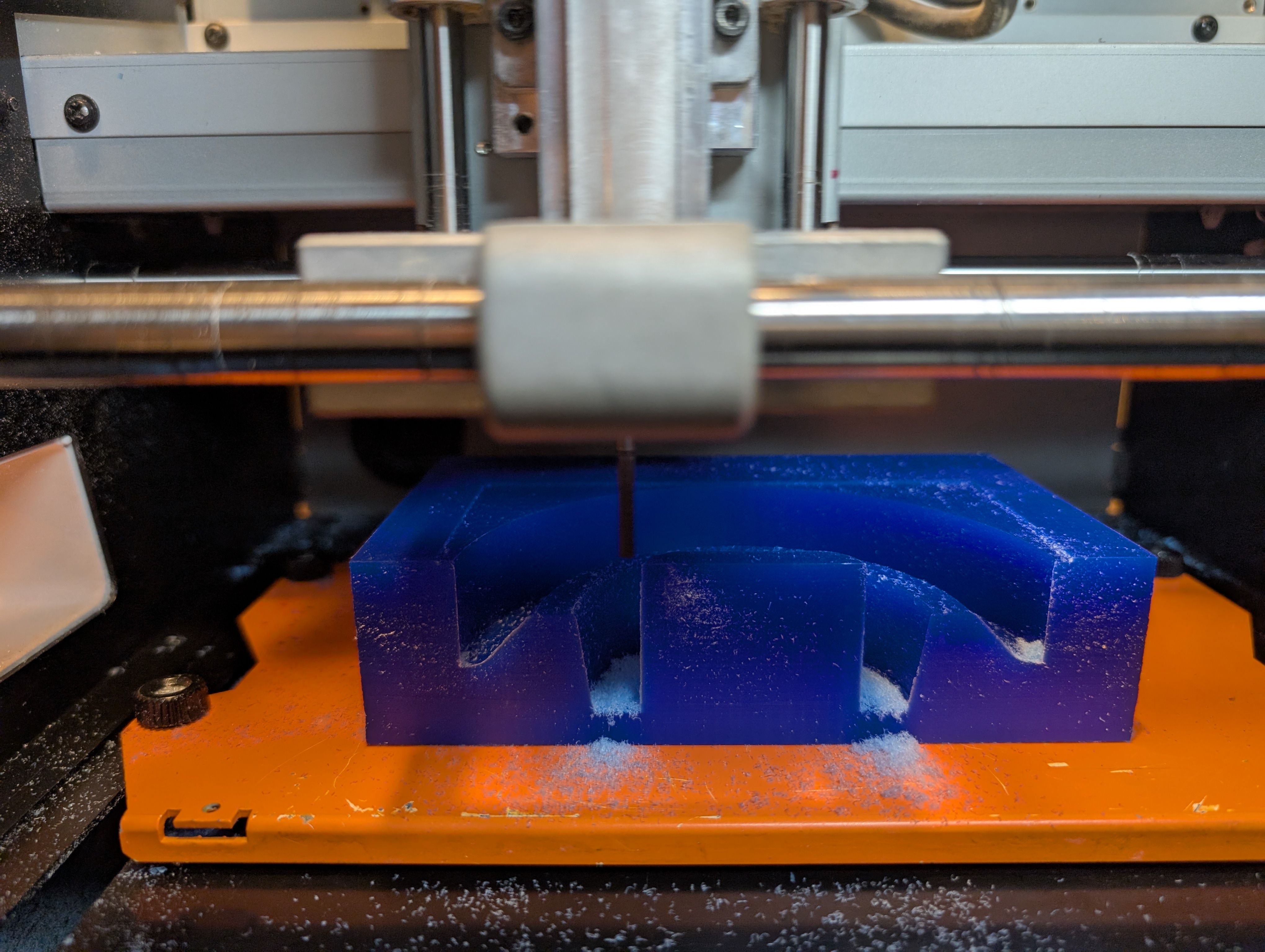
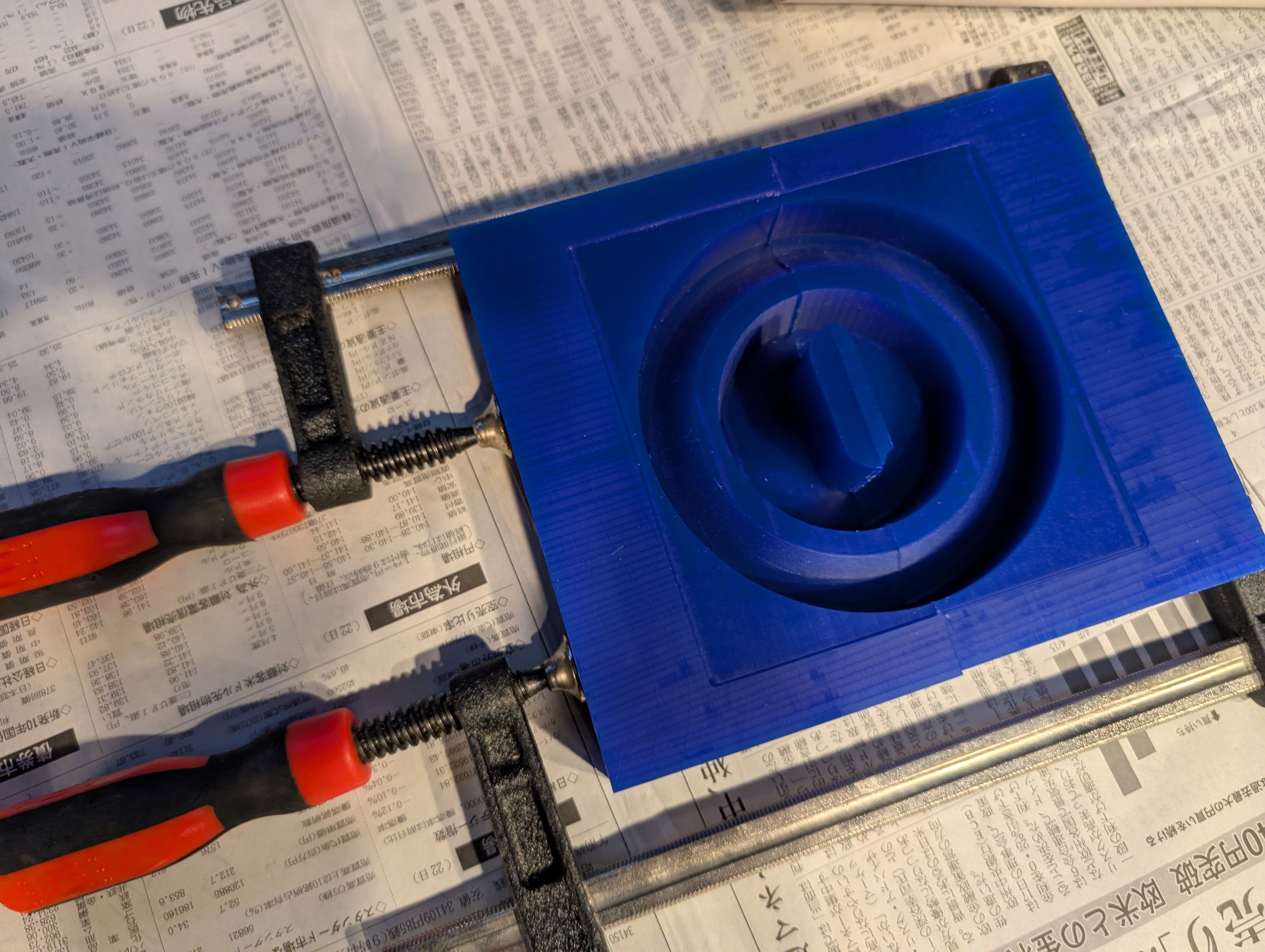
Result for 1st half mold
Make 2nd half mold
After 1st half mold, since the hole is too thin to cut out, I made the hole bigger
and made 2nd half
mold.
Setting for roughing
Setting for finishing
Time for roughing: 2:49
Time for finishing: 1:36
Roughing
Finishing
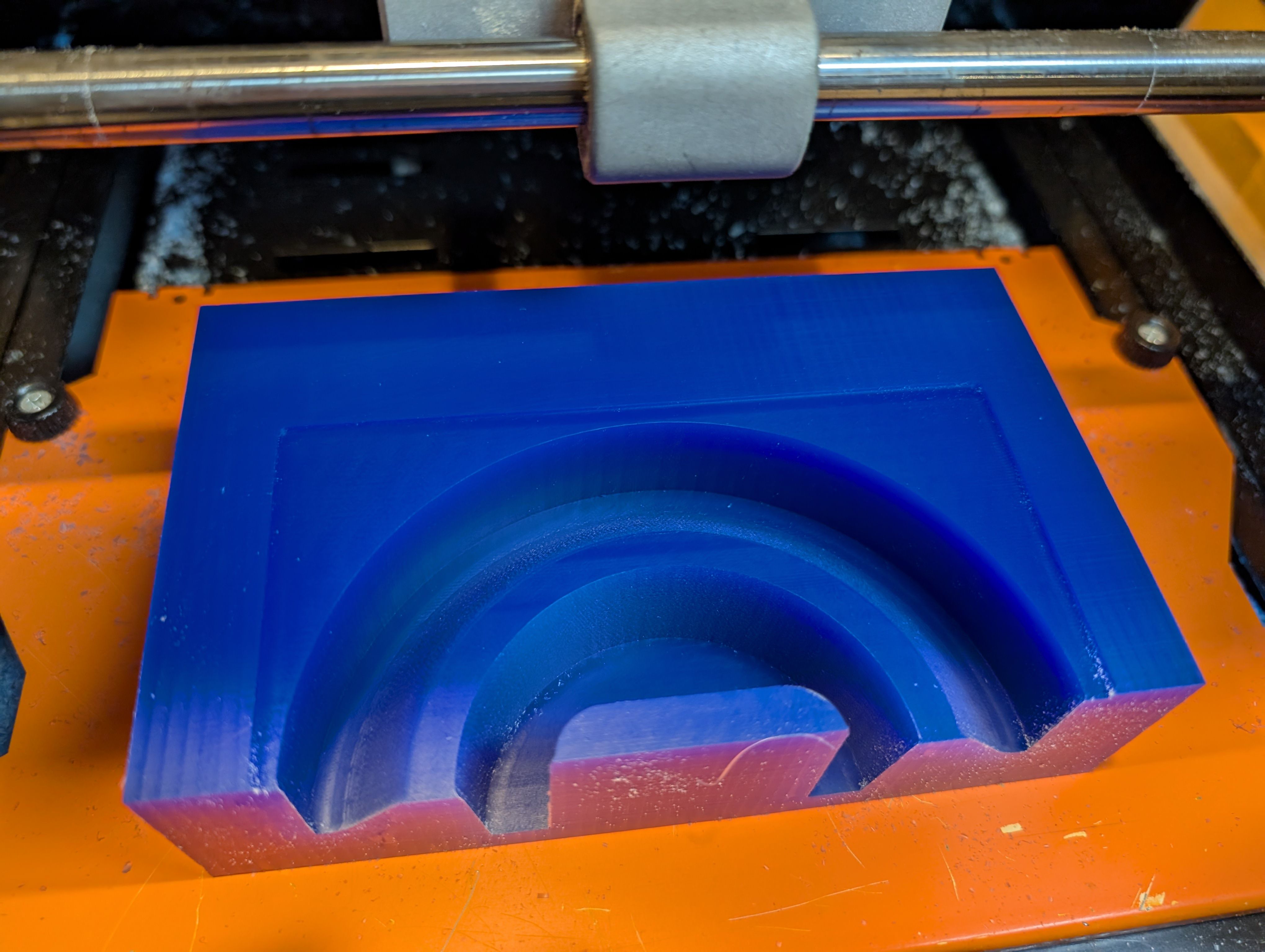
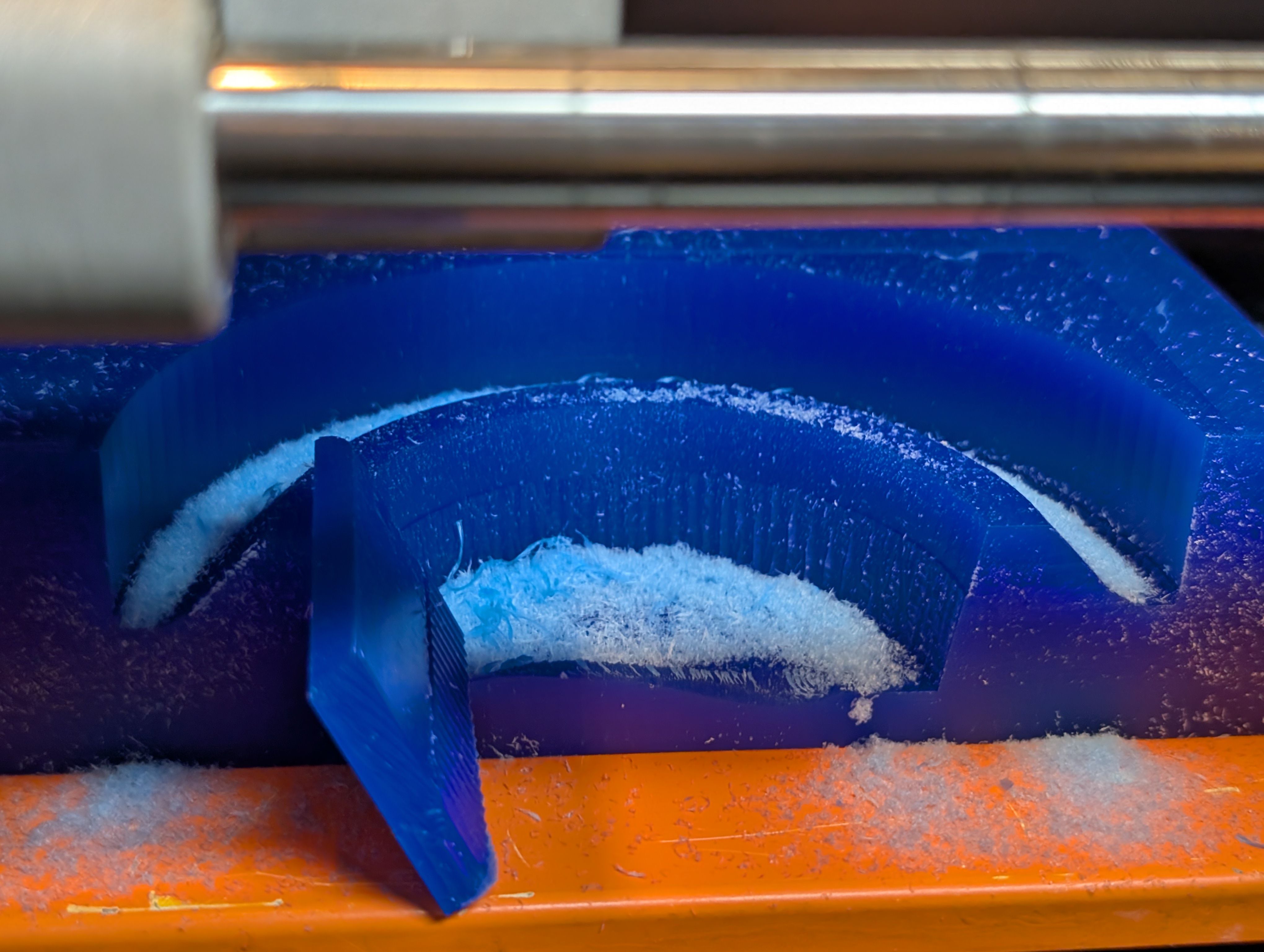
*A large amount of waste was generated
It fits nicely
The broken part was fixed with glue.
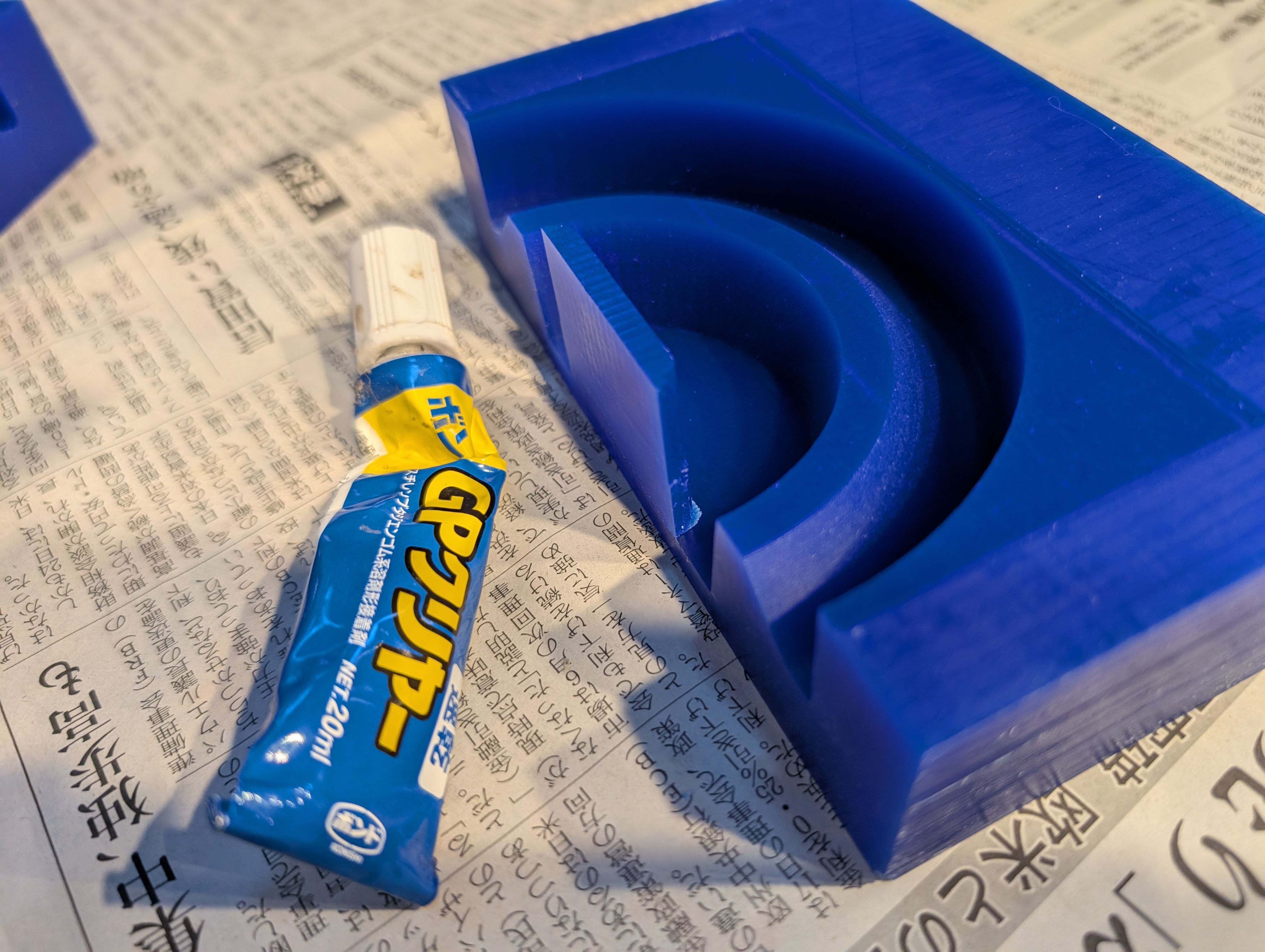
The 2 parts were also fixed together with glue and clamp.
Casting
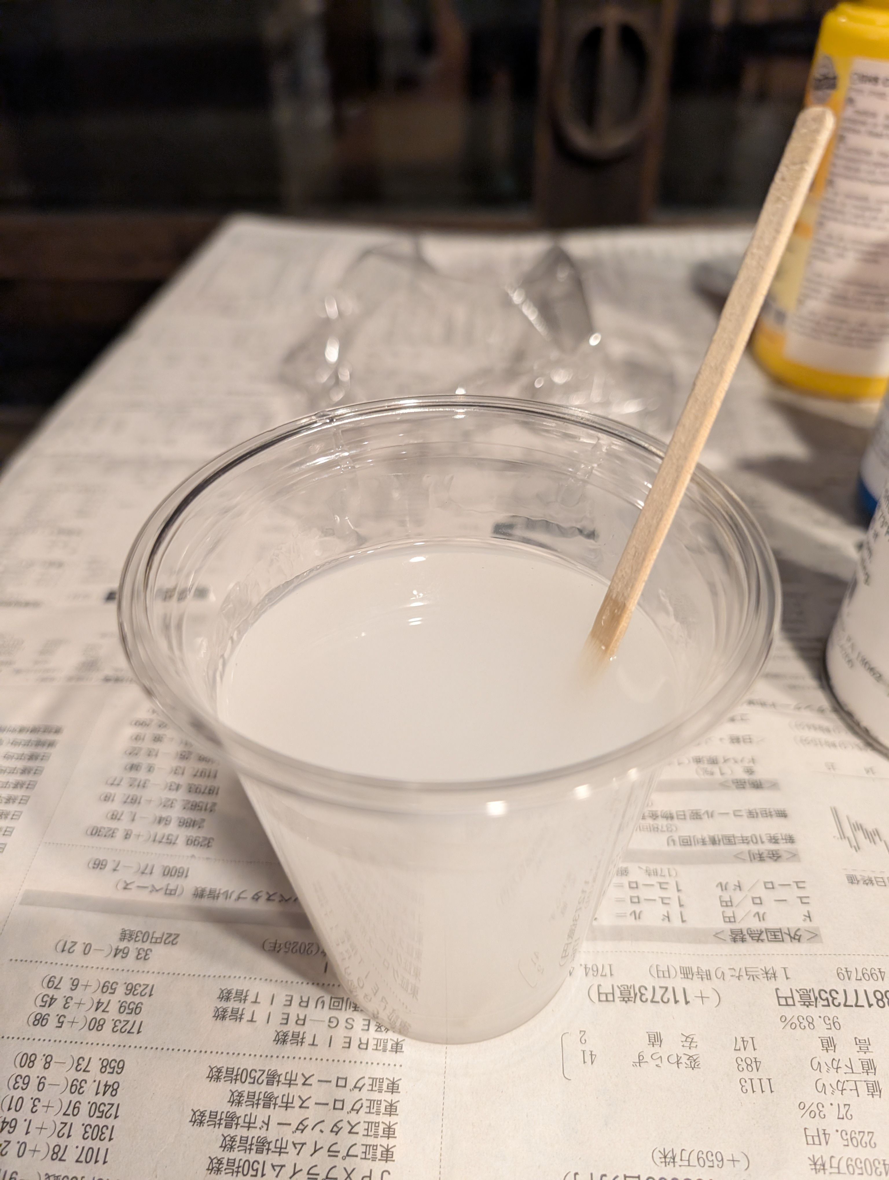
I used Ecoflex 00-30. Part A : Part B = 1 : 1 = 120g : 120g
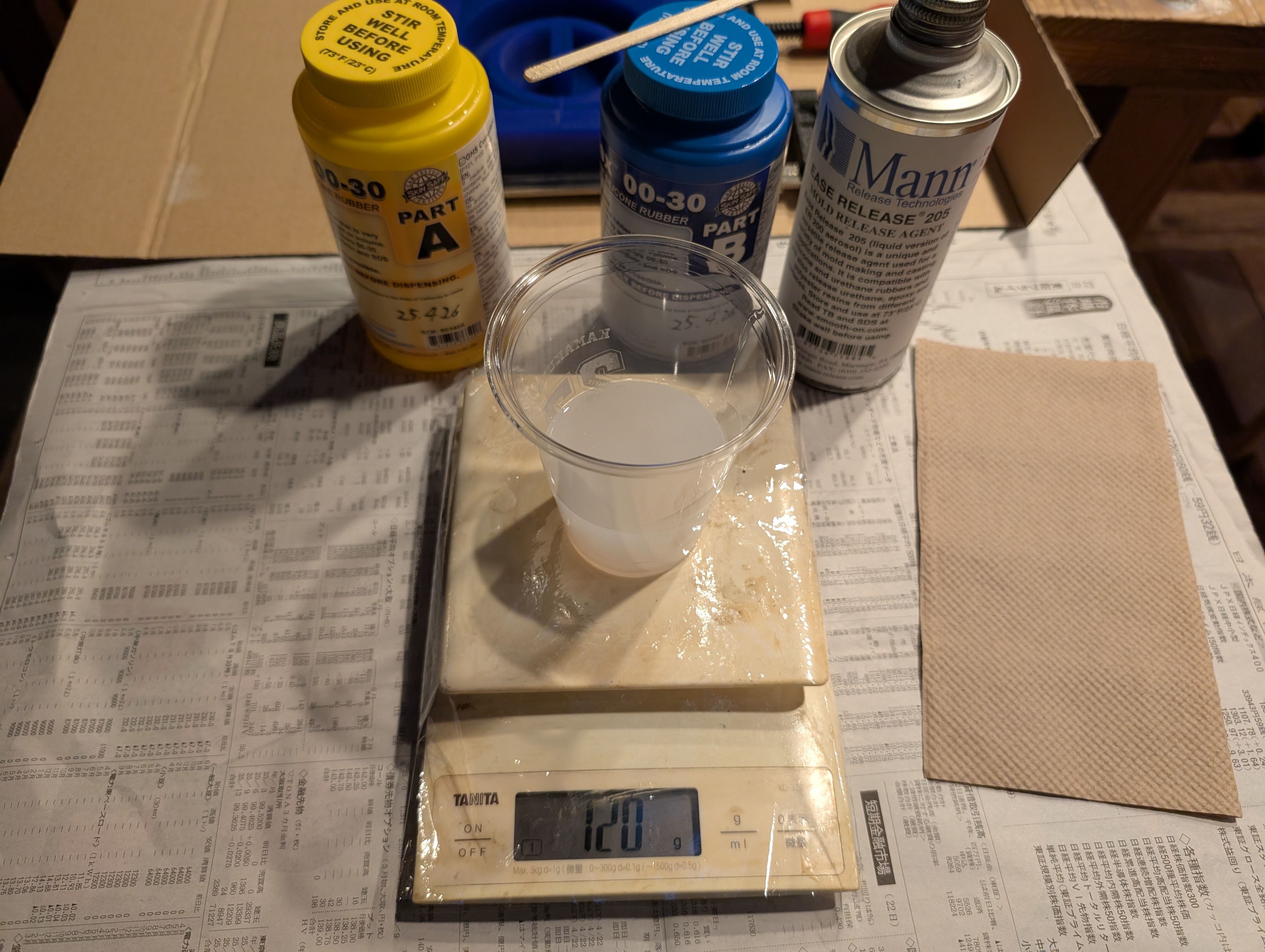
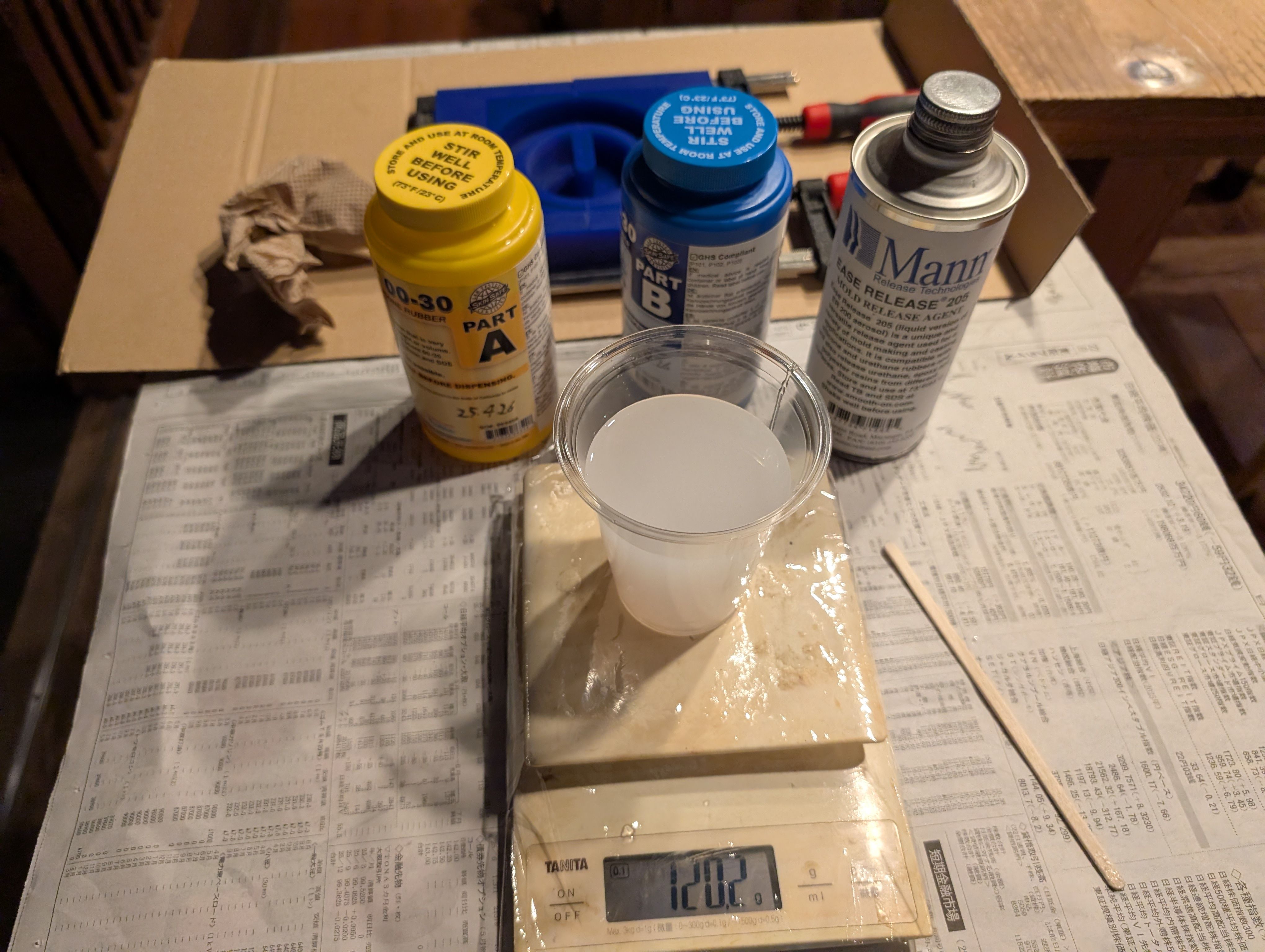
Mix them well and put to the mold
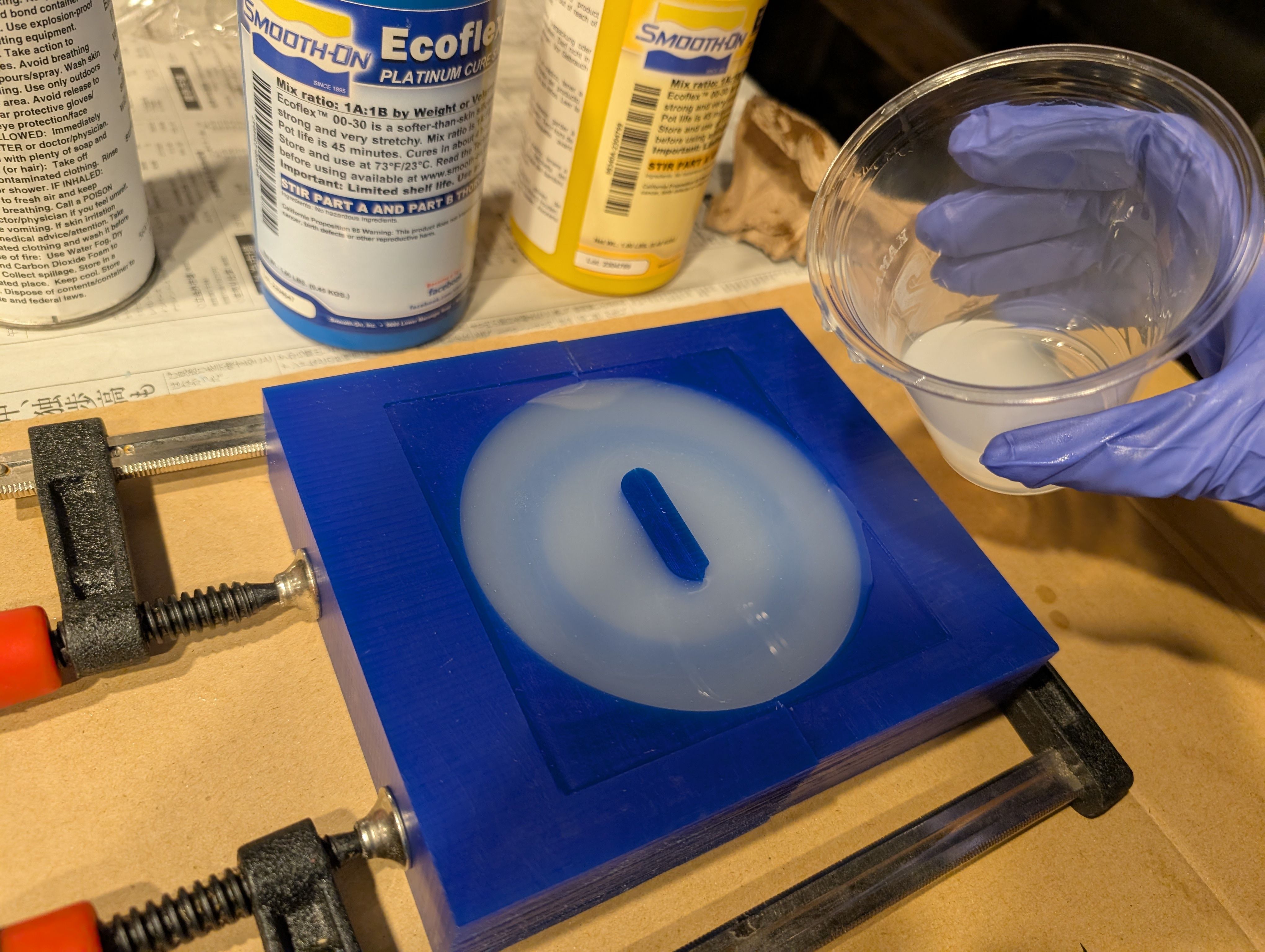
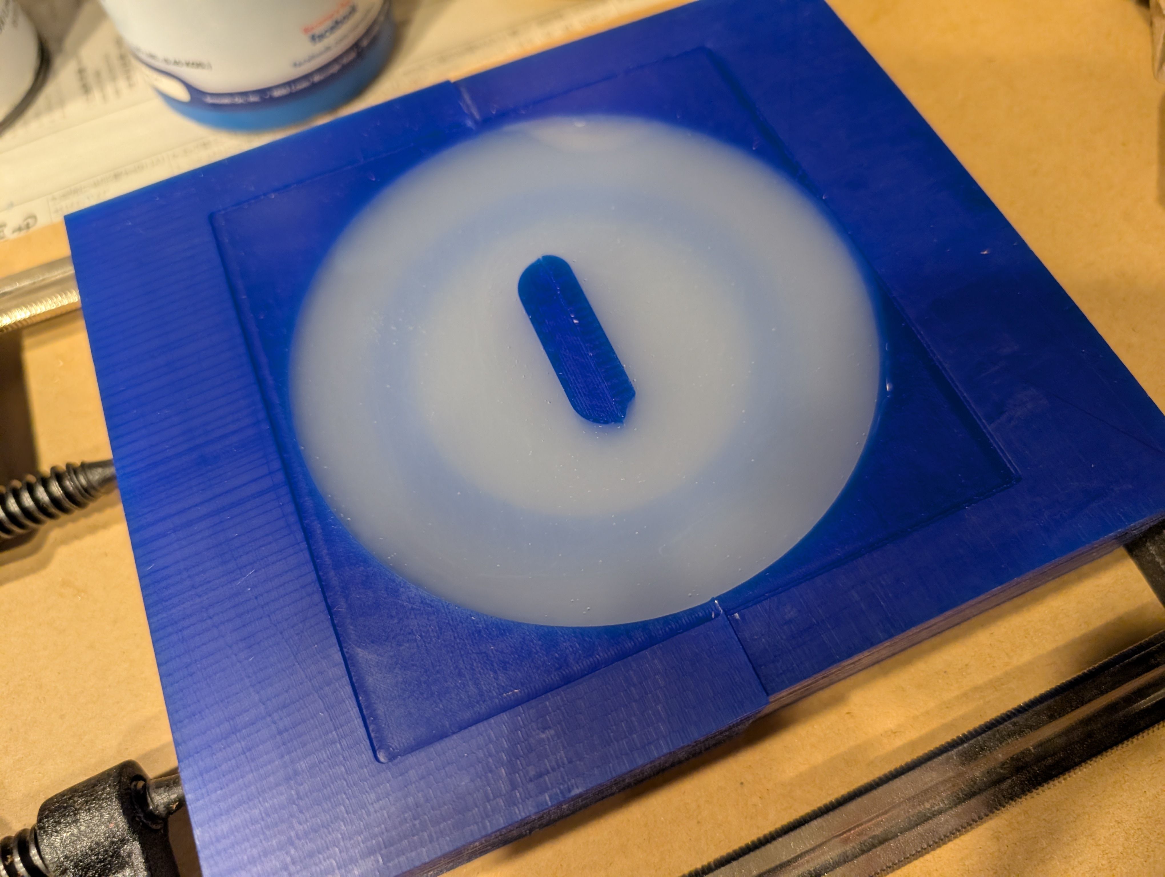
Result
It fit well with the glass!
For the details, please see Week13 Molding and Casting page.
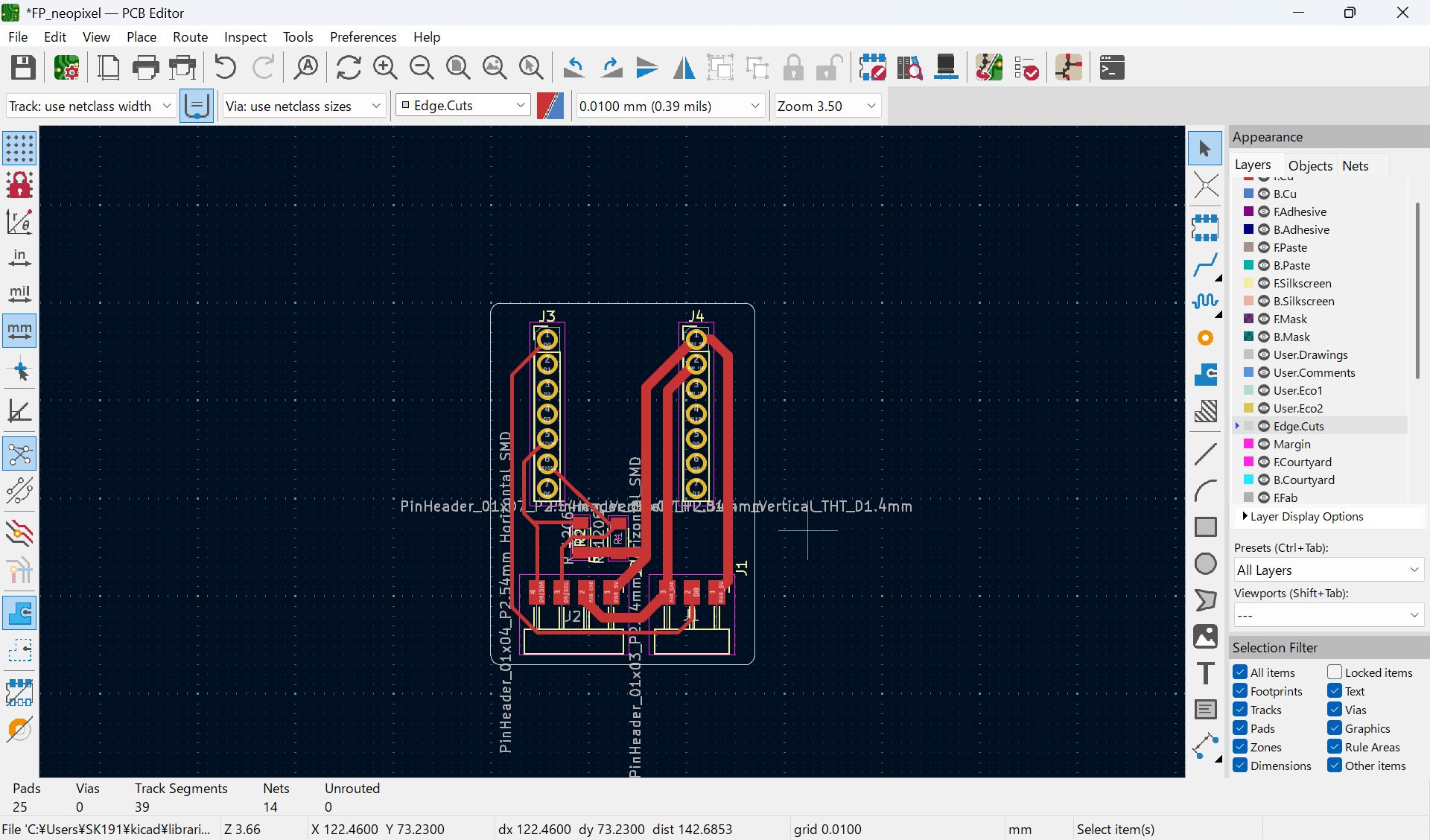
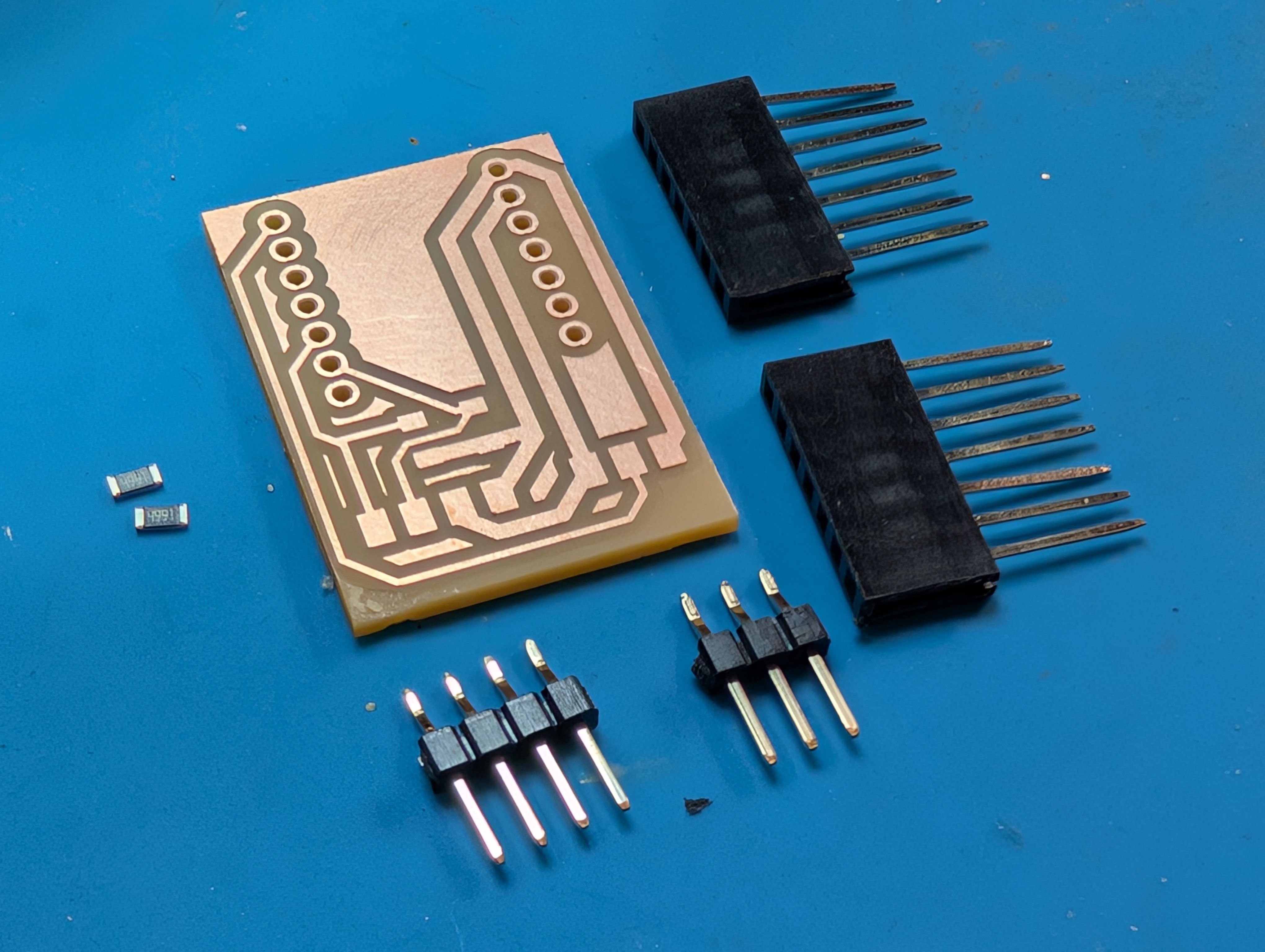
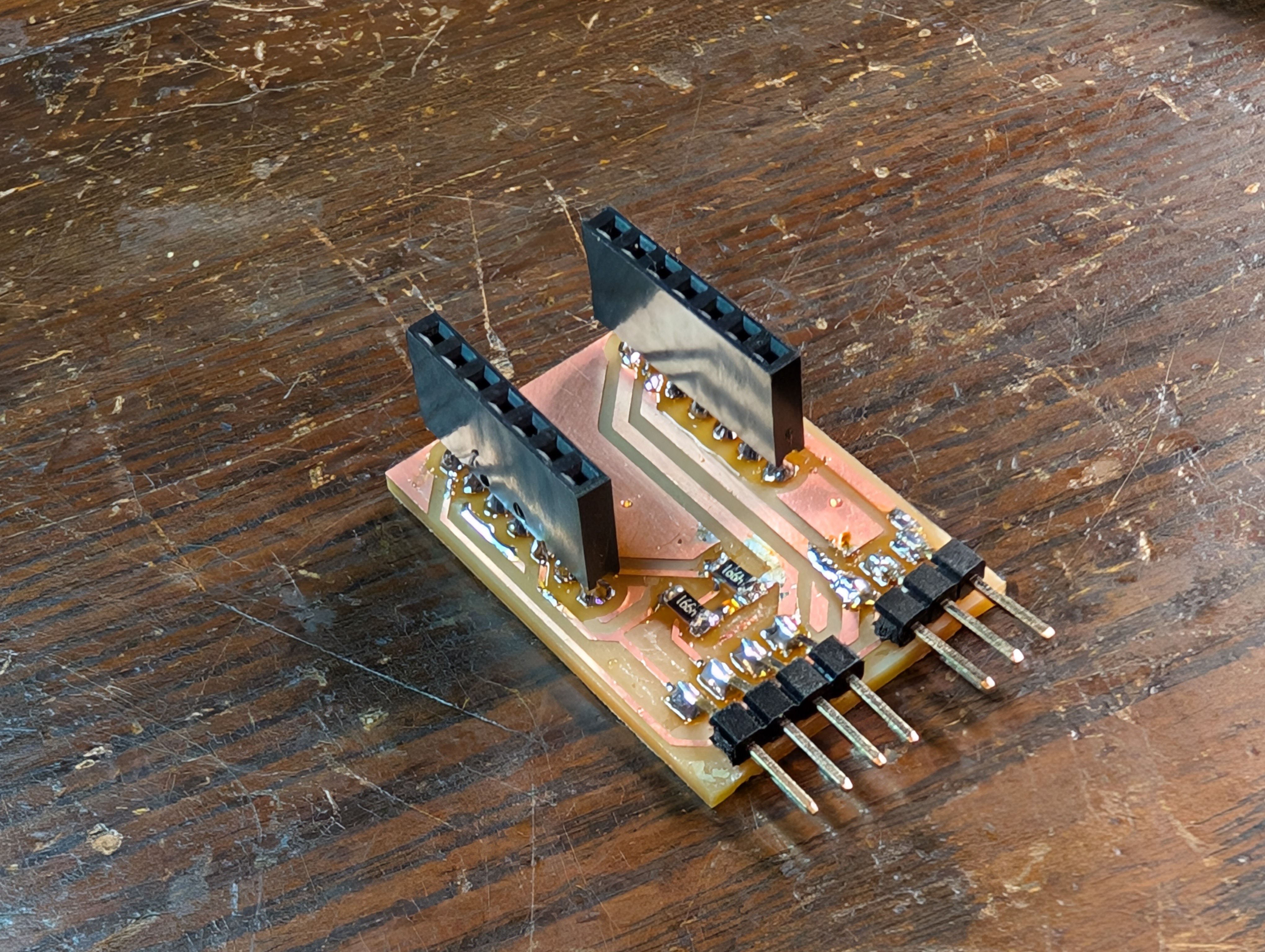
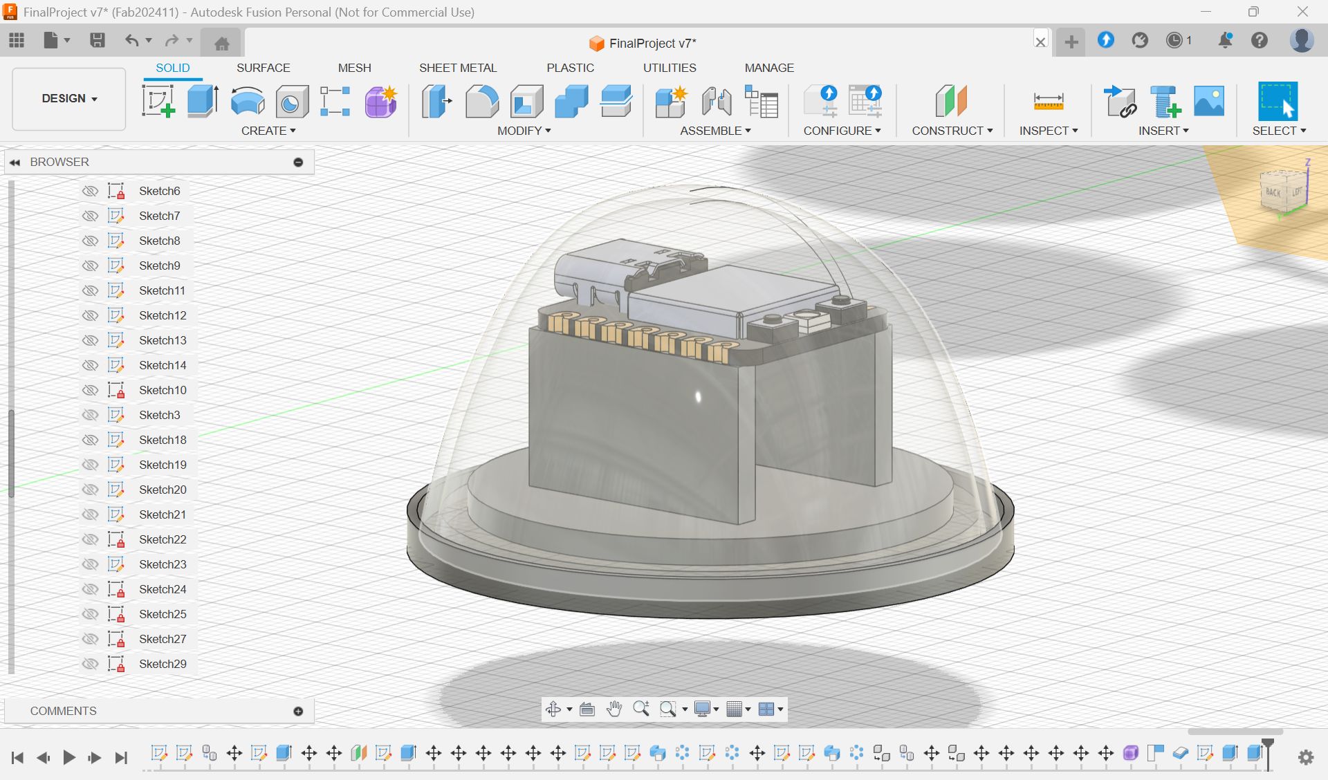
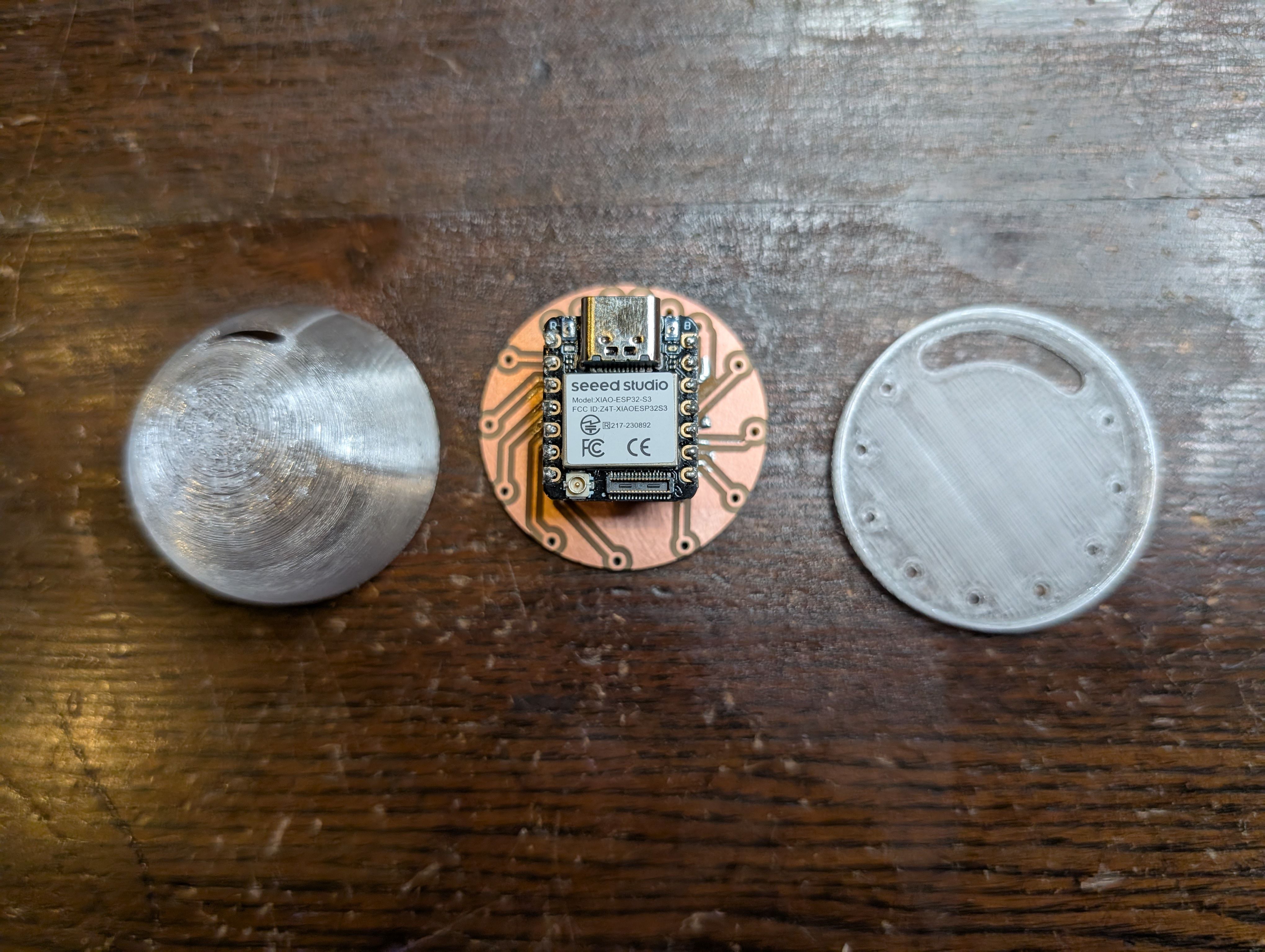
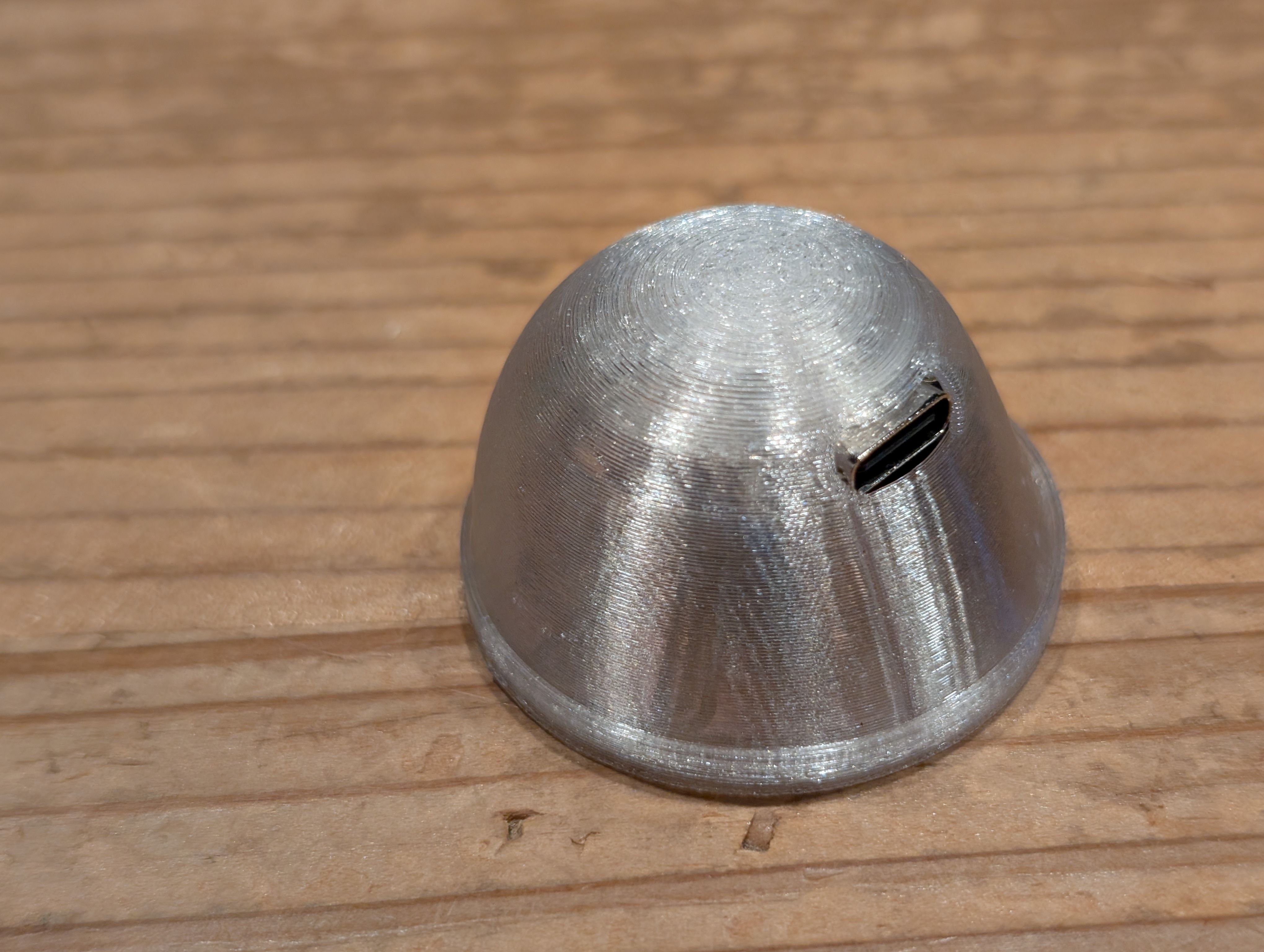
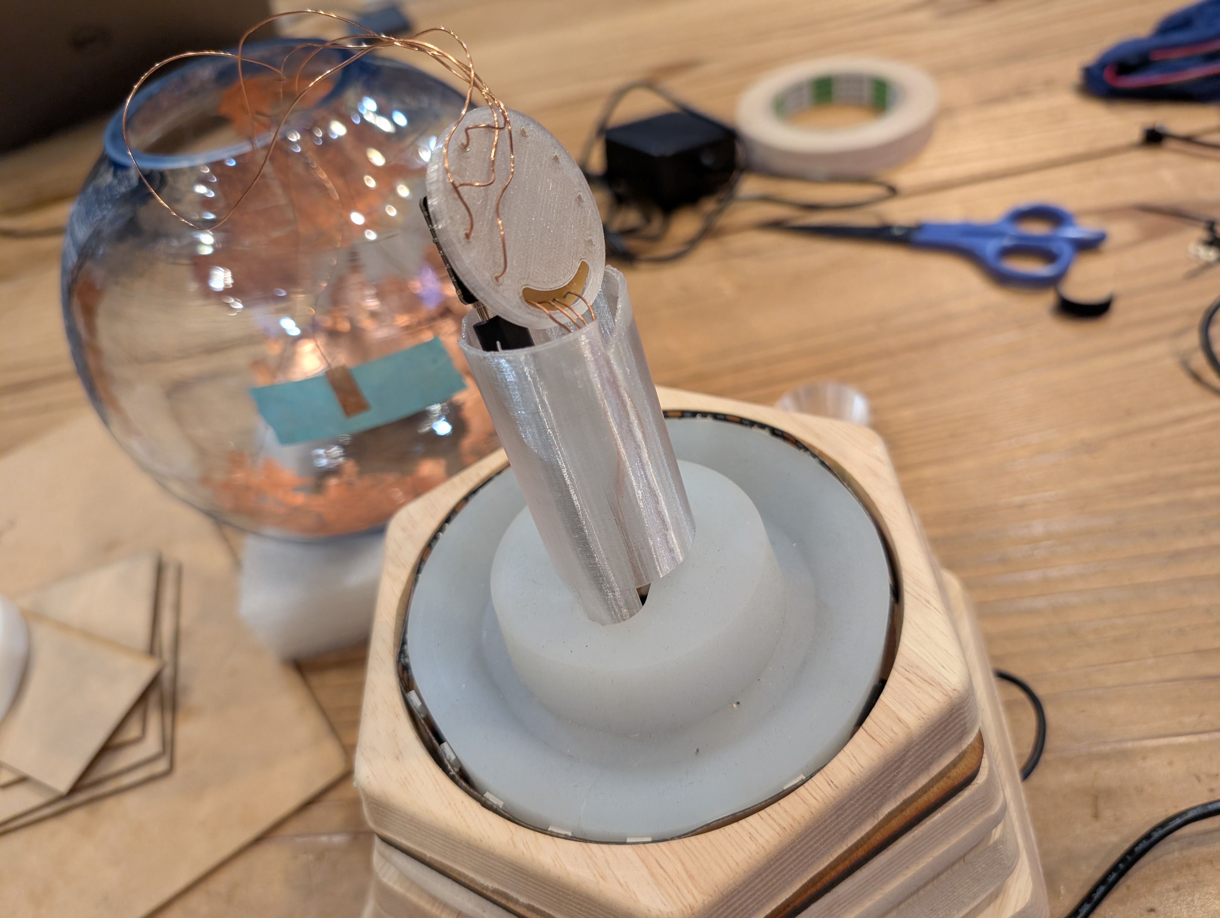
PCB Case and support - 3d printing
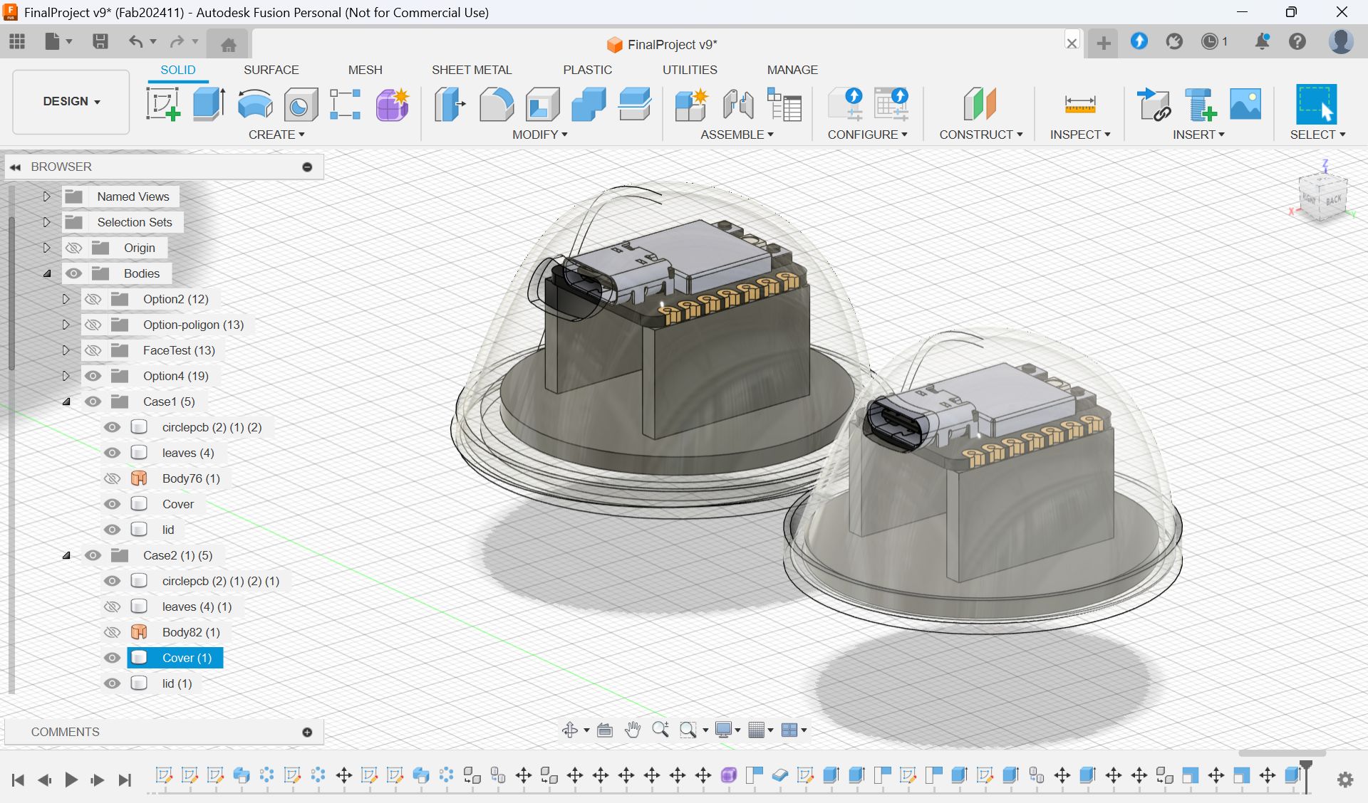
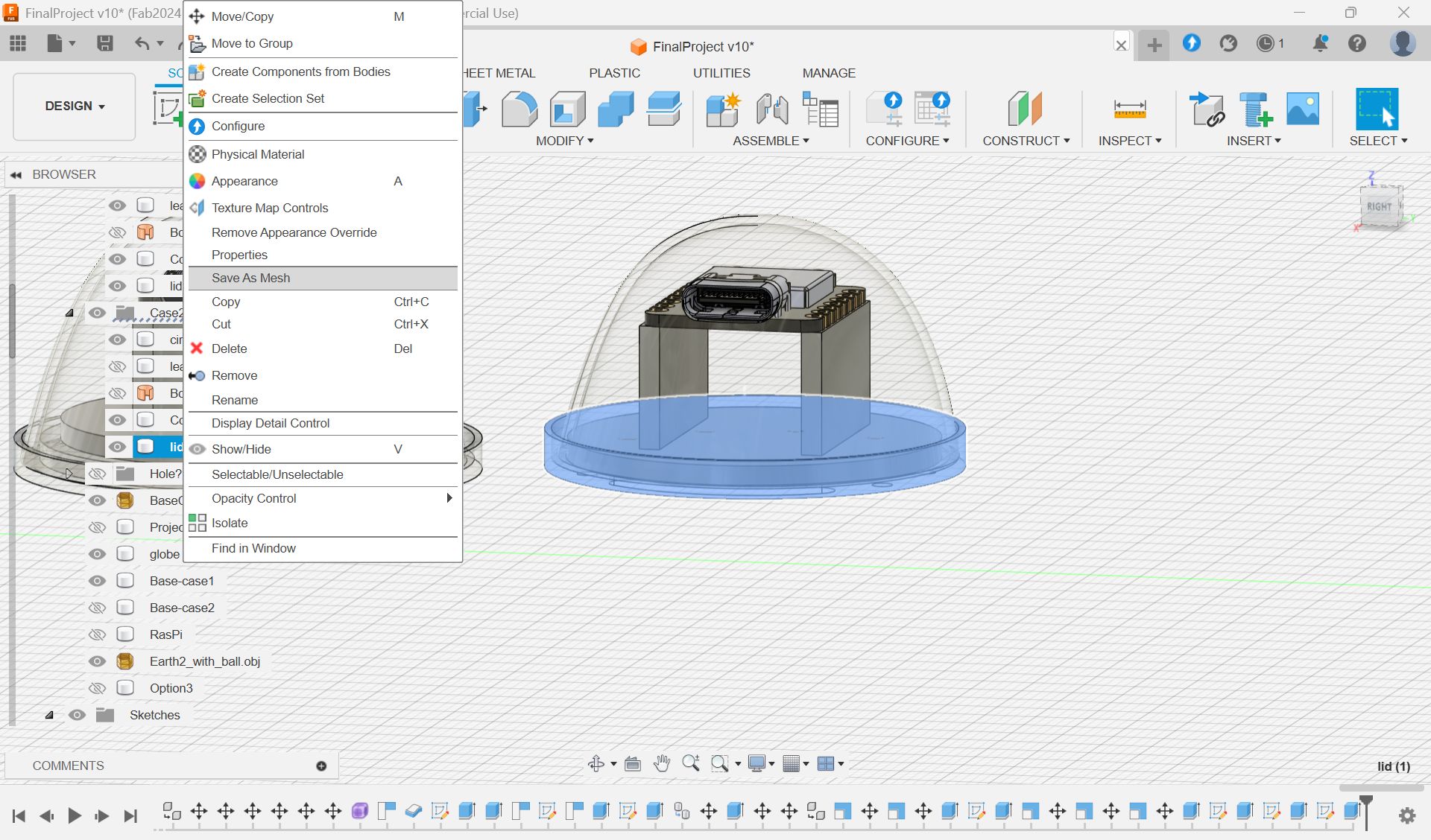
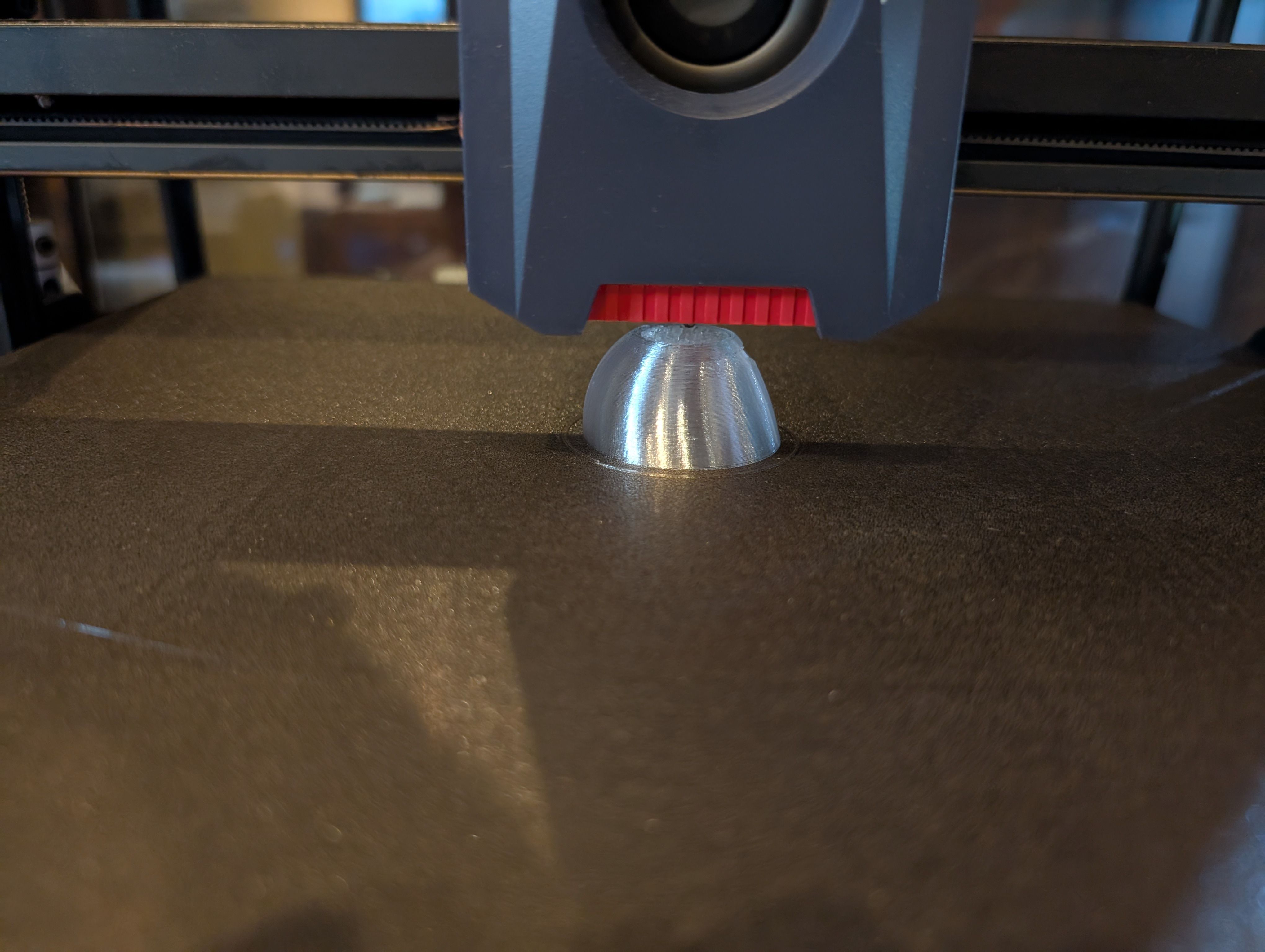
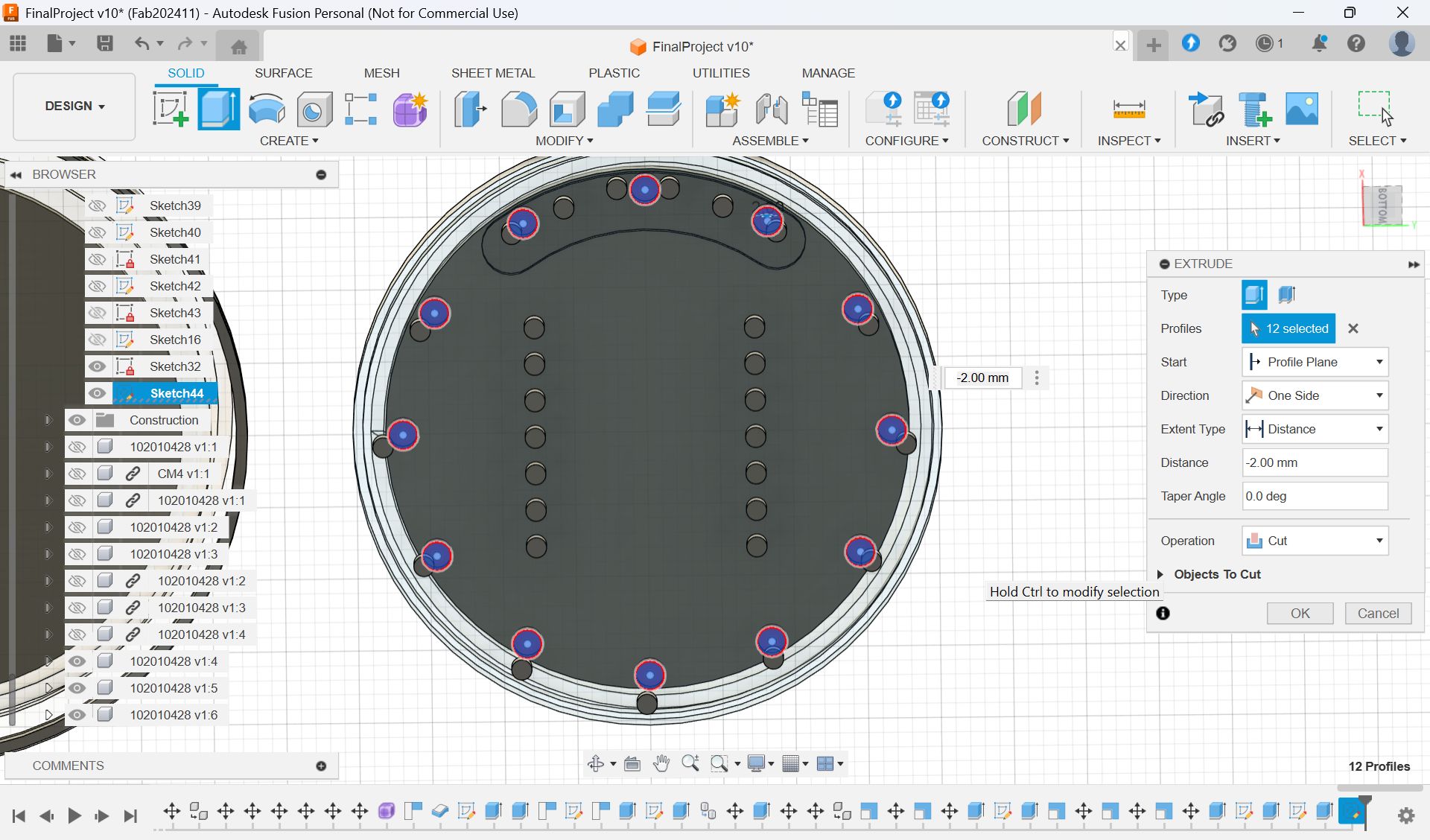
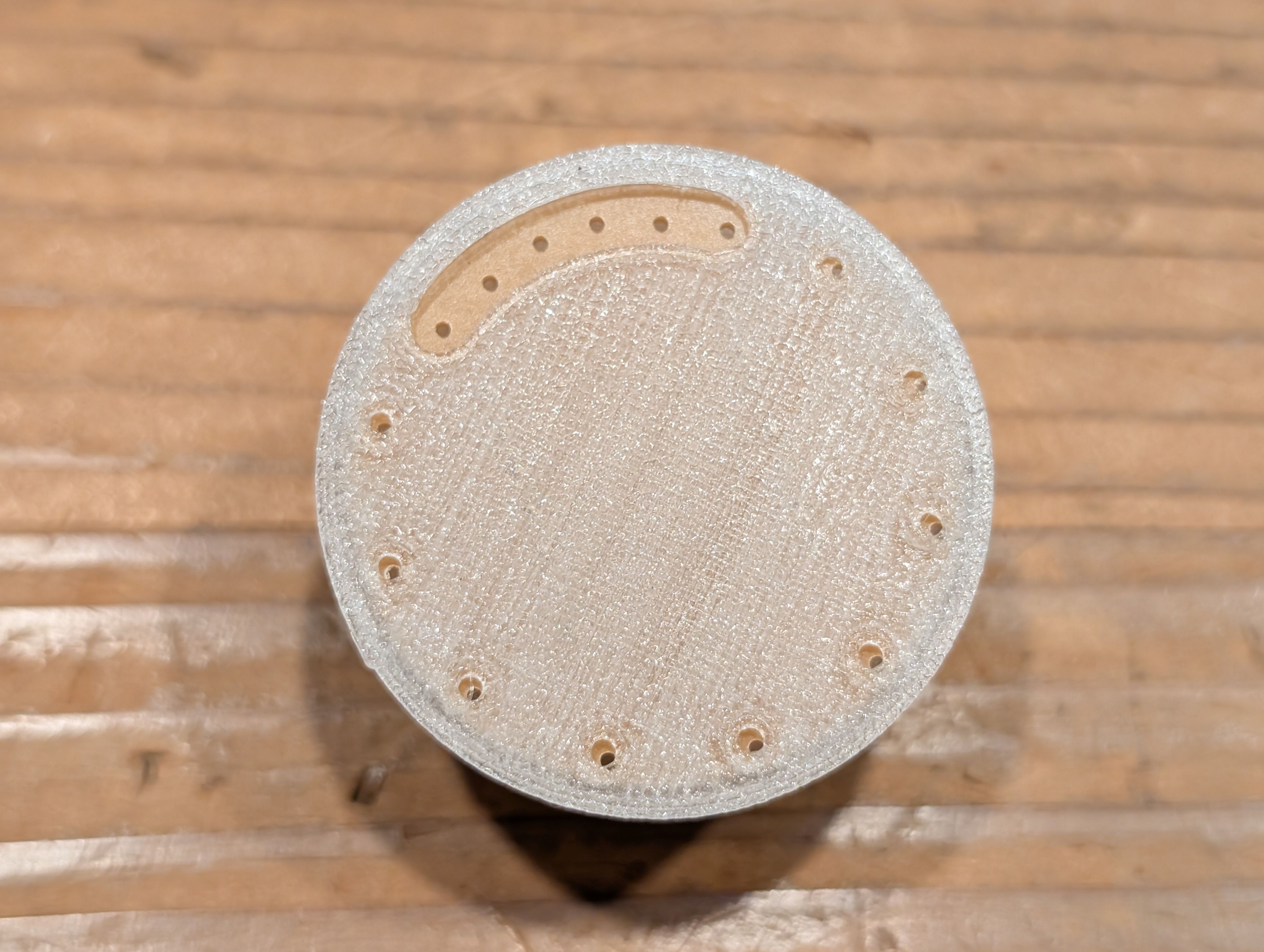
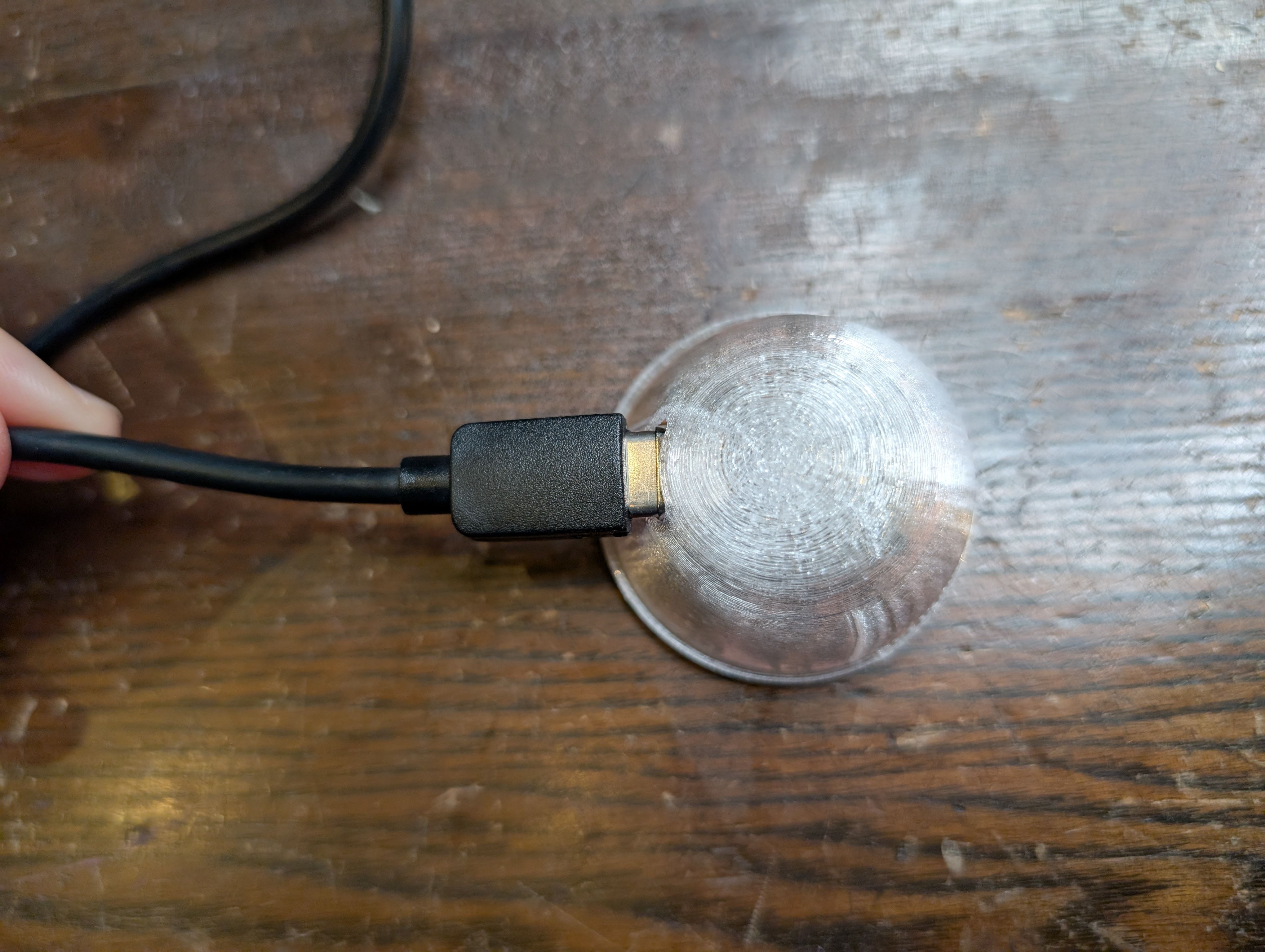
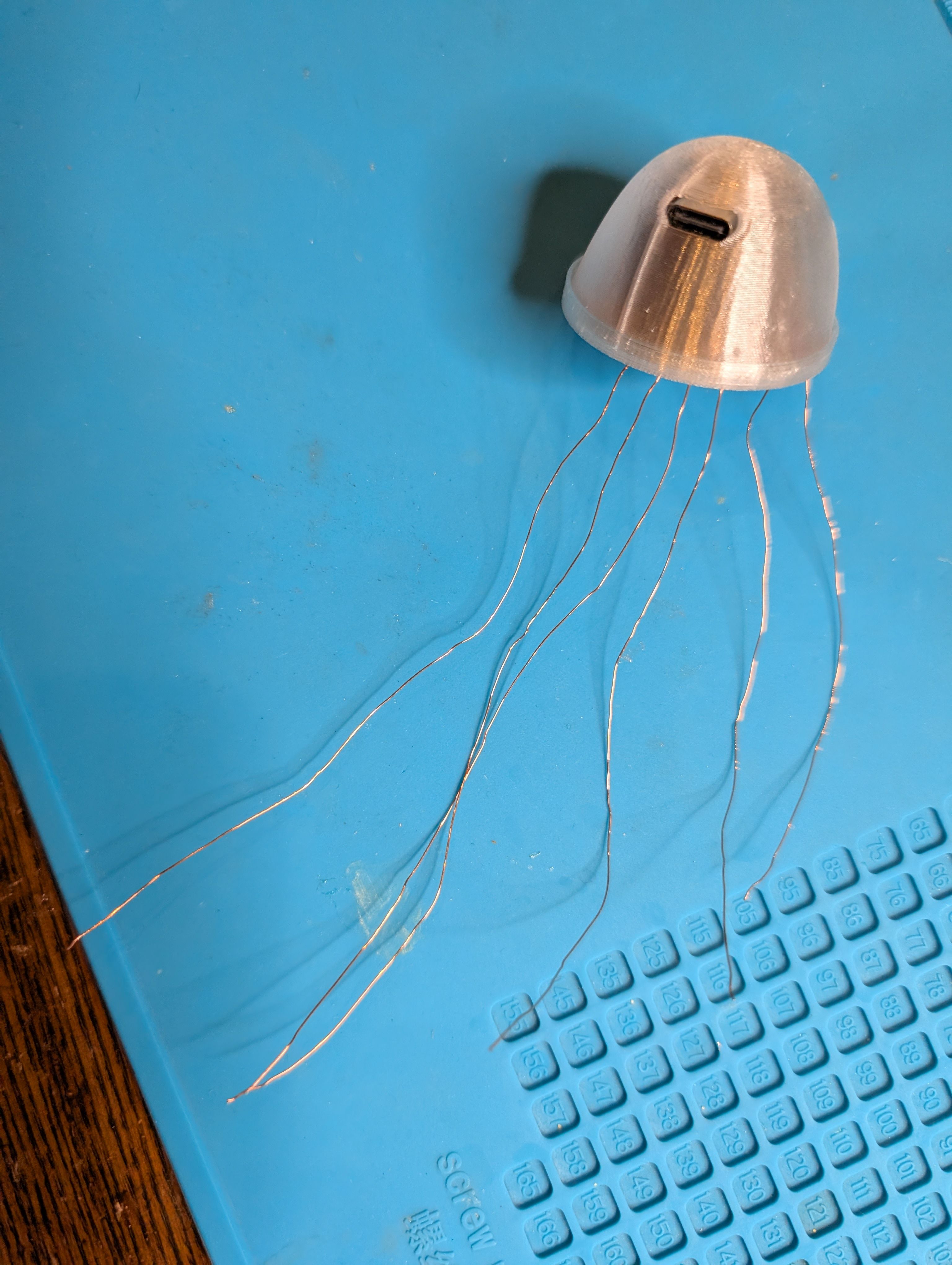
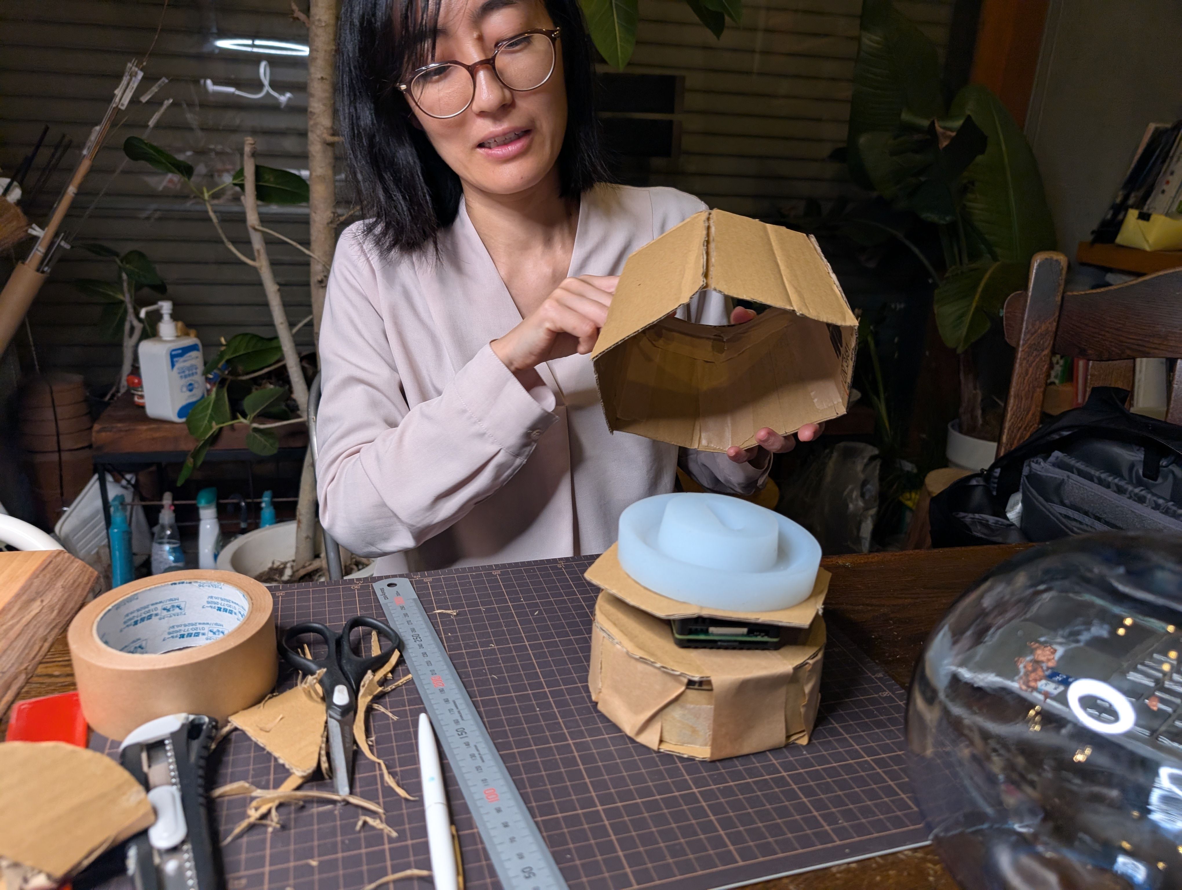
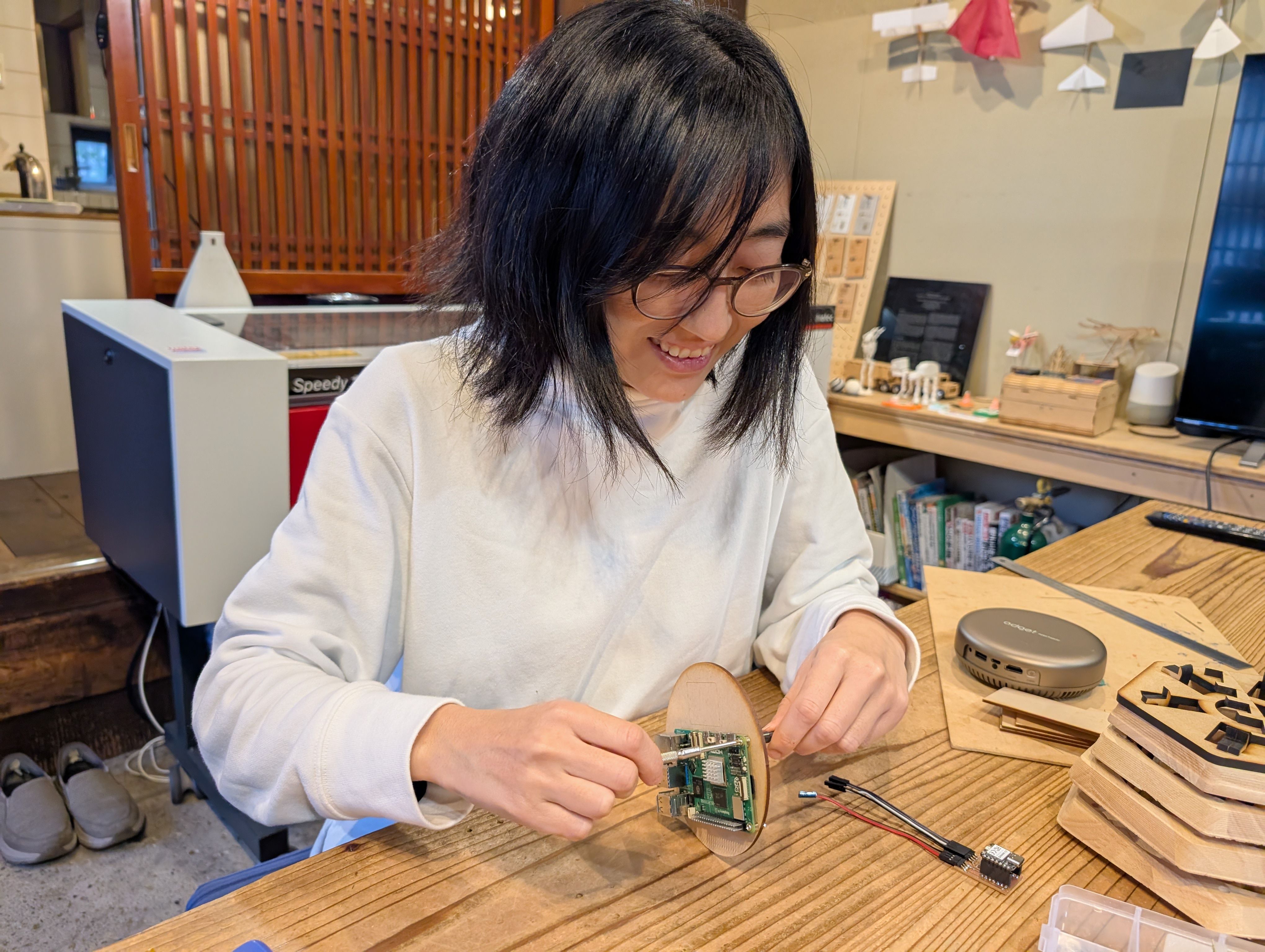
In the week 15, I made a case for XIAO ESP32S3. I thought it will be nice if xiao is in the case and hidden since I want to put it in the middle of the glass globe.
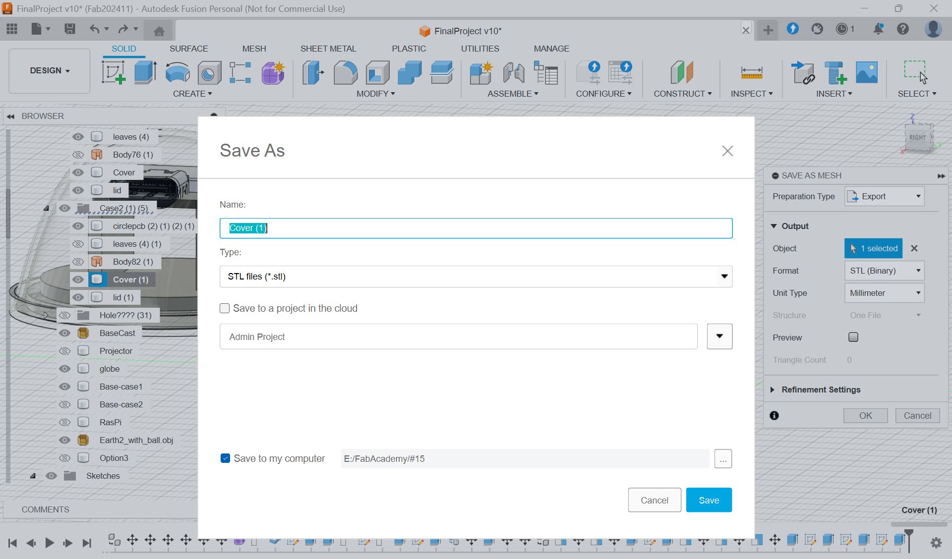
Made a case for xiao
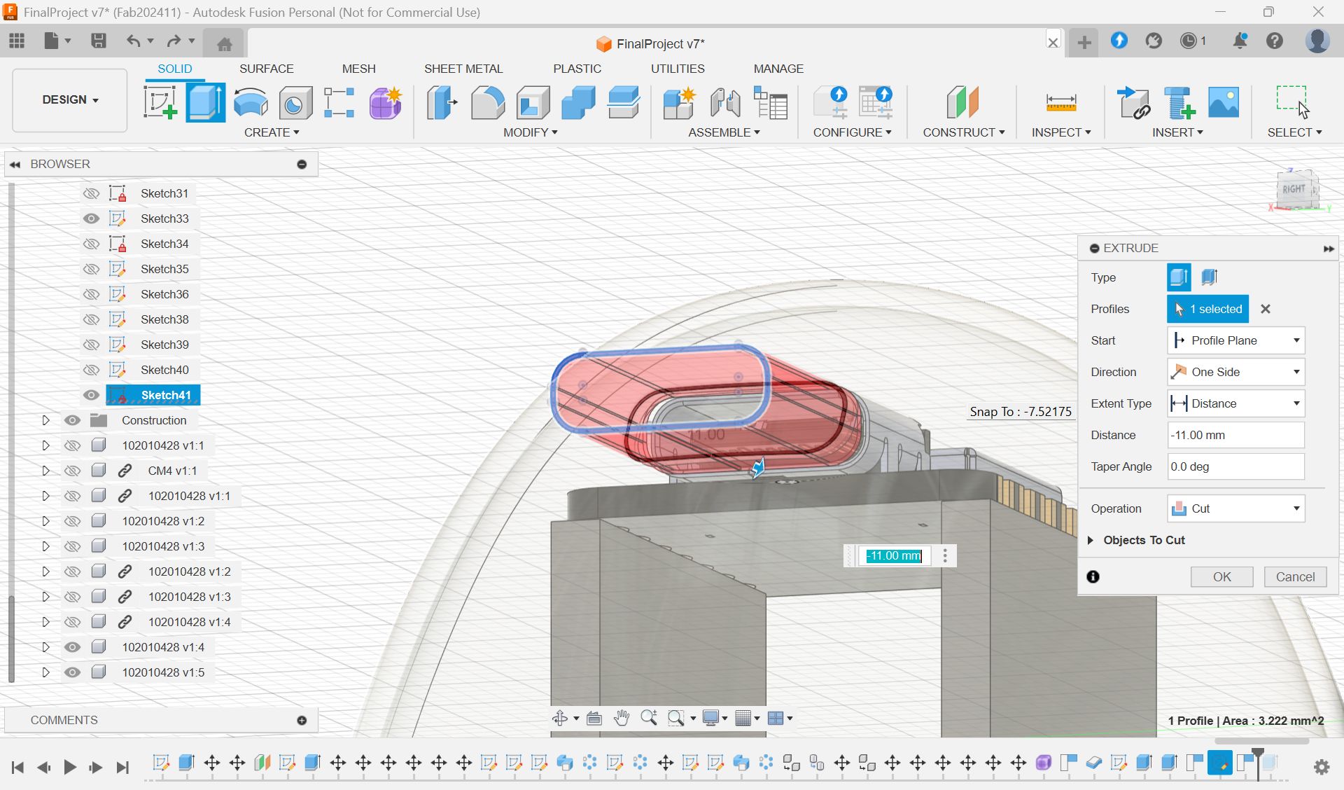
Select parts”body”, and Save As Mesh, and export as stl file for 3D print
3D print settings
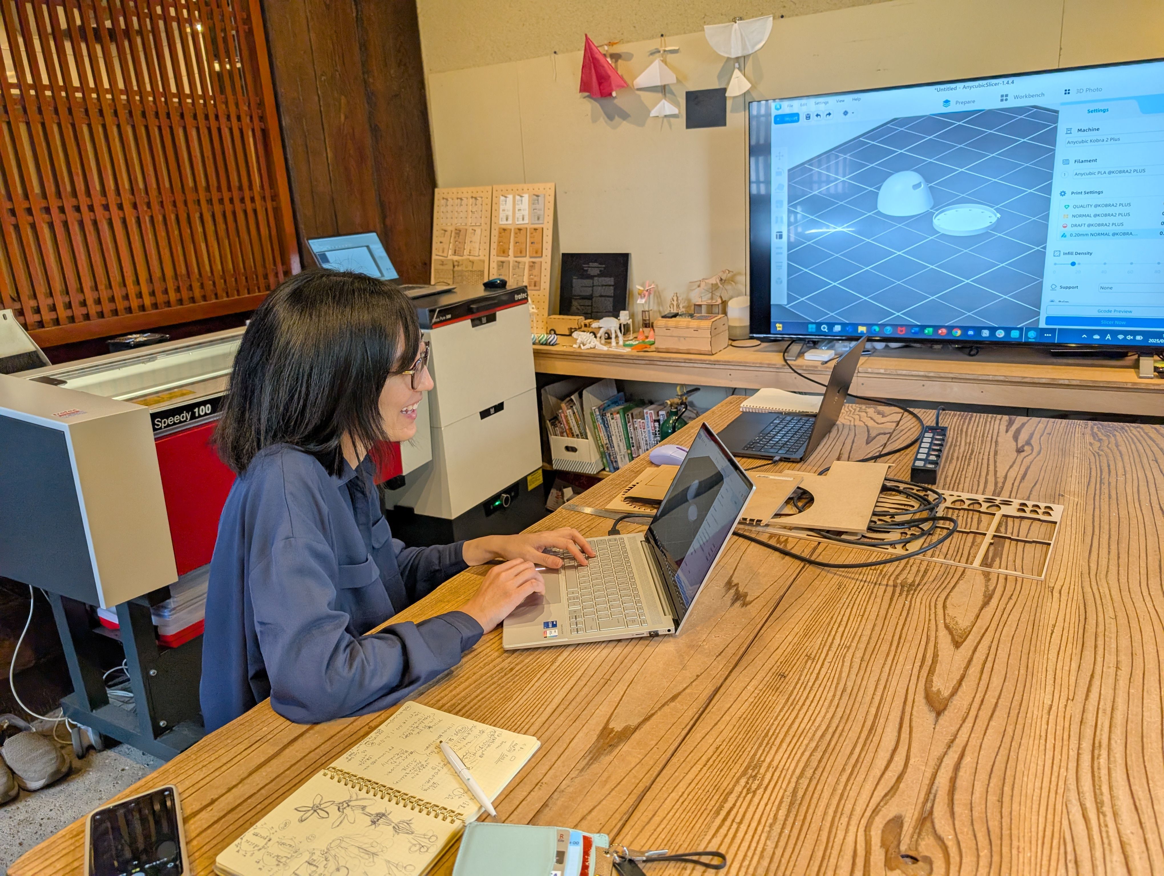
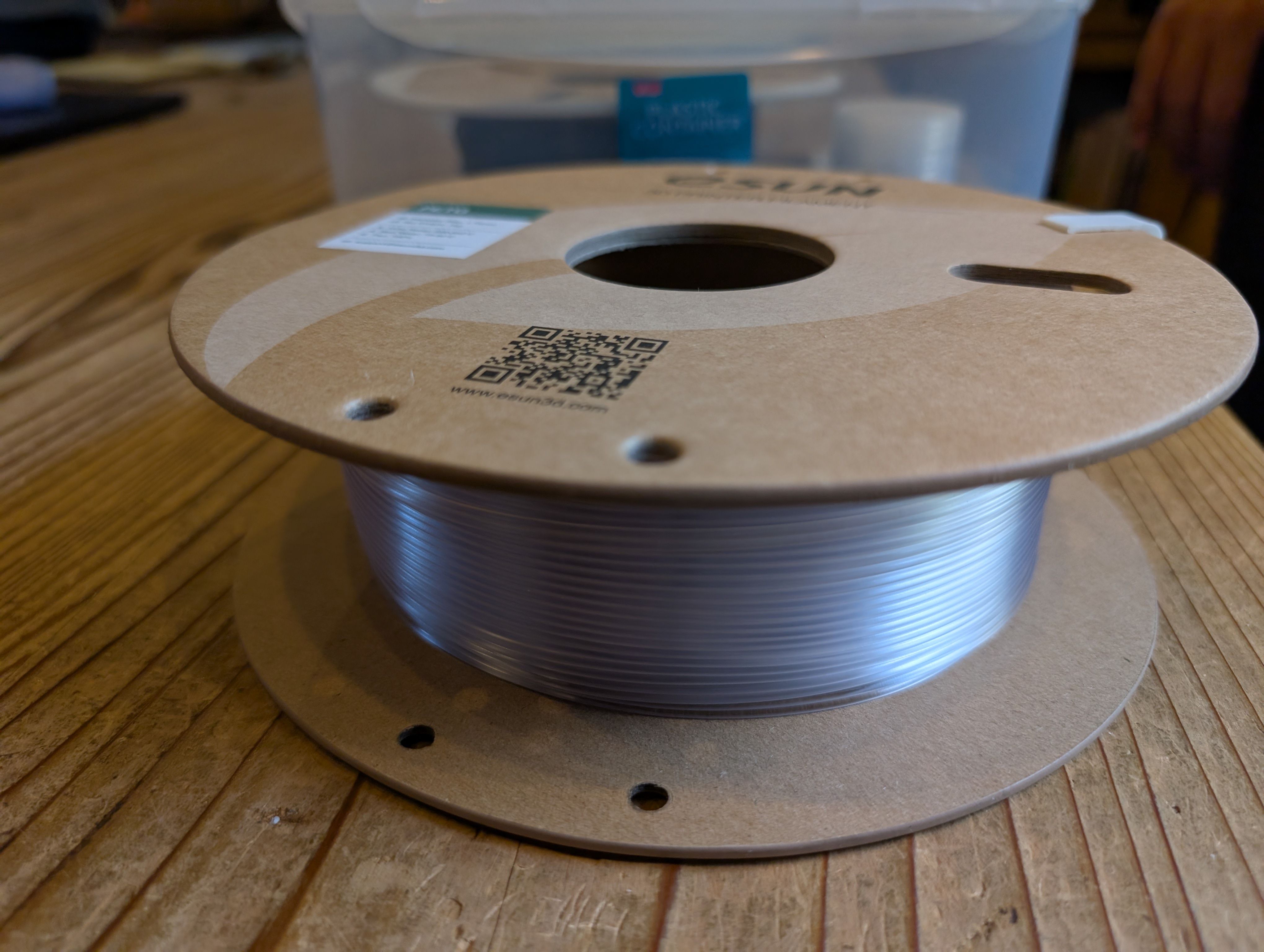
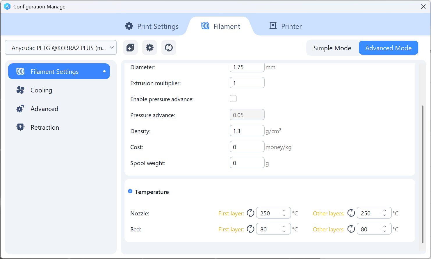
I used PETG (clear color), since it is clearer than PLA (recommended by Yamamoto-san)
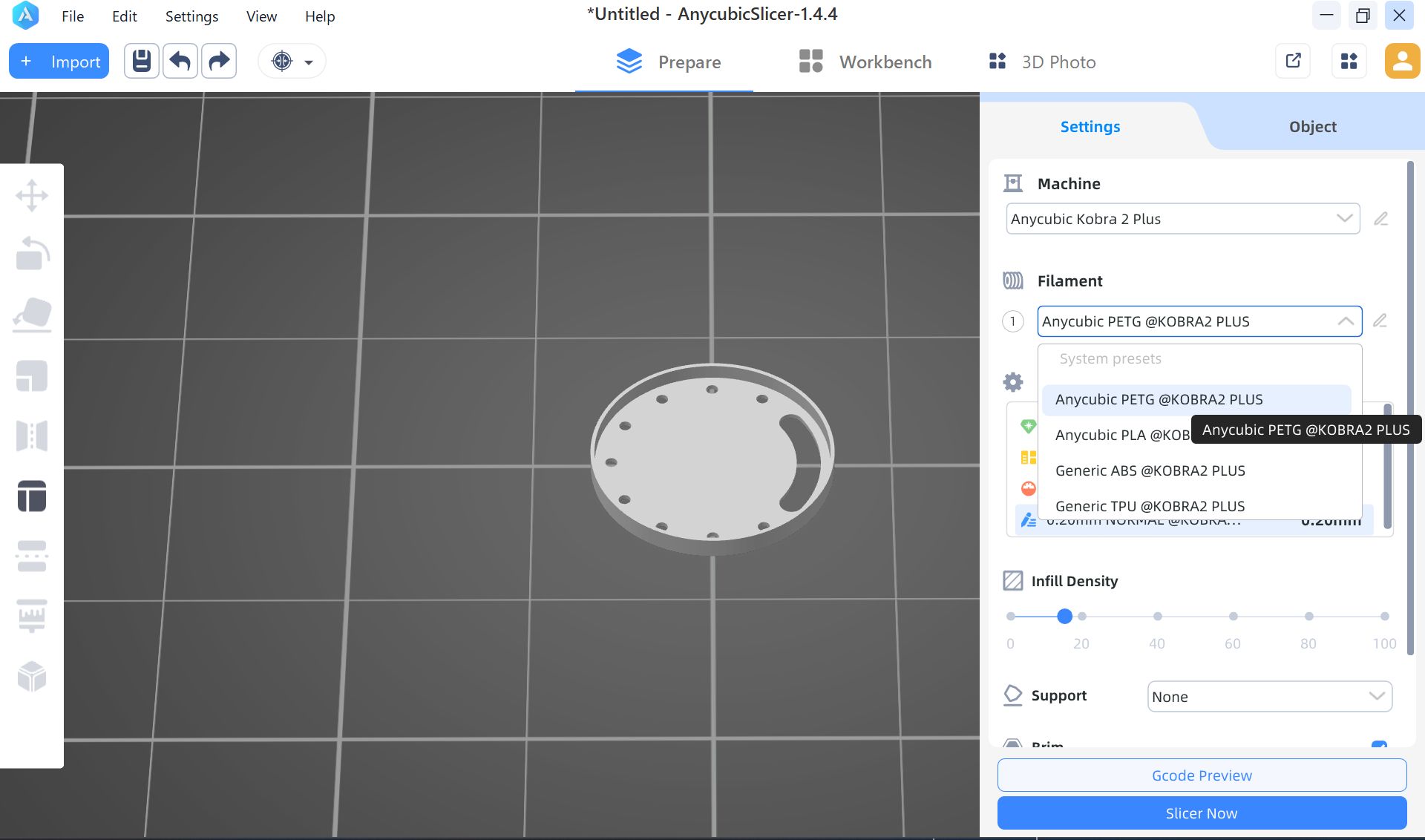
Head temperature: 250 - Changes transparency Bed temperature: 80 - Changes adhesion to the bed
First layer: first layer Other layers: layers after 2
For a lid, no support, since it is flat
For Case part, I set the support as Organic(= tree shape, easy to take off)
Print it out.
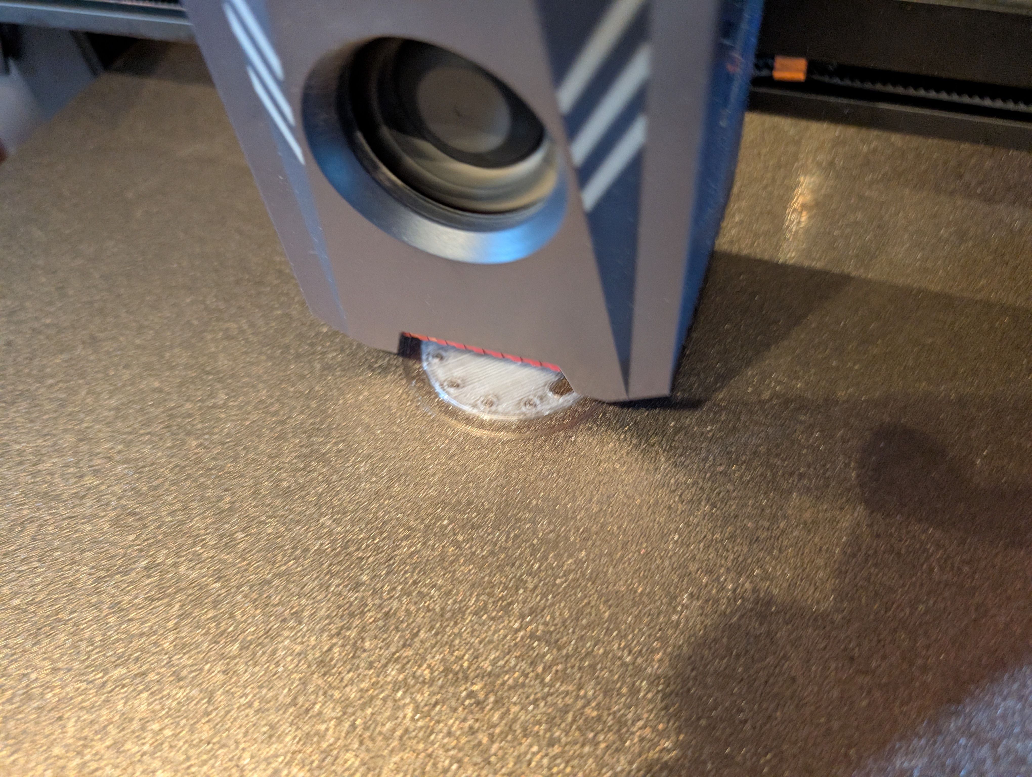
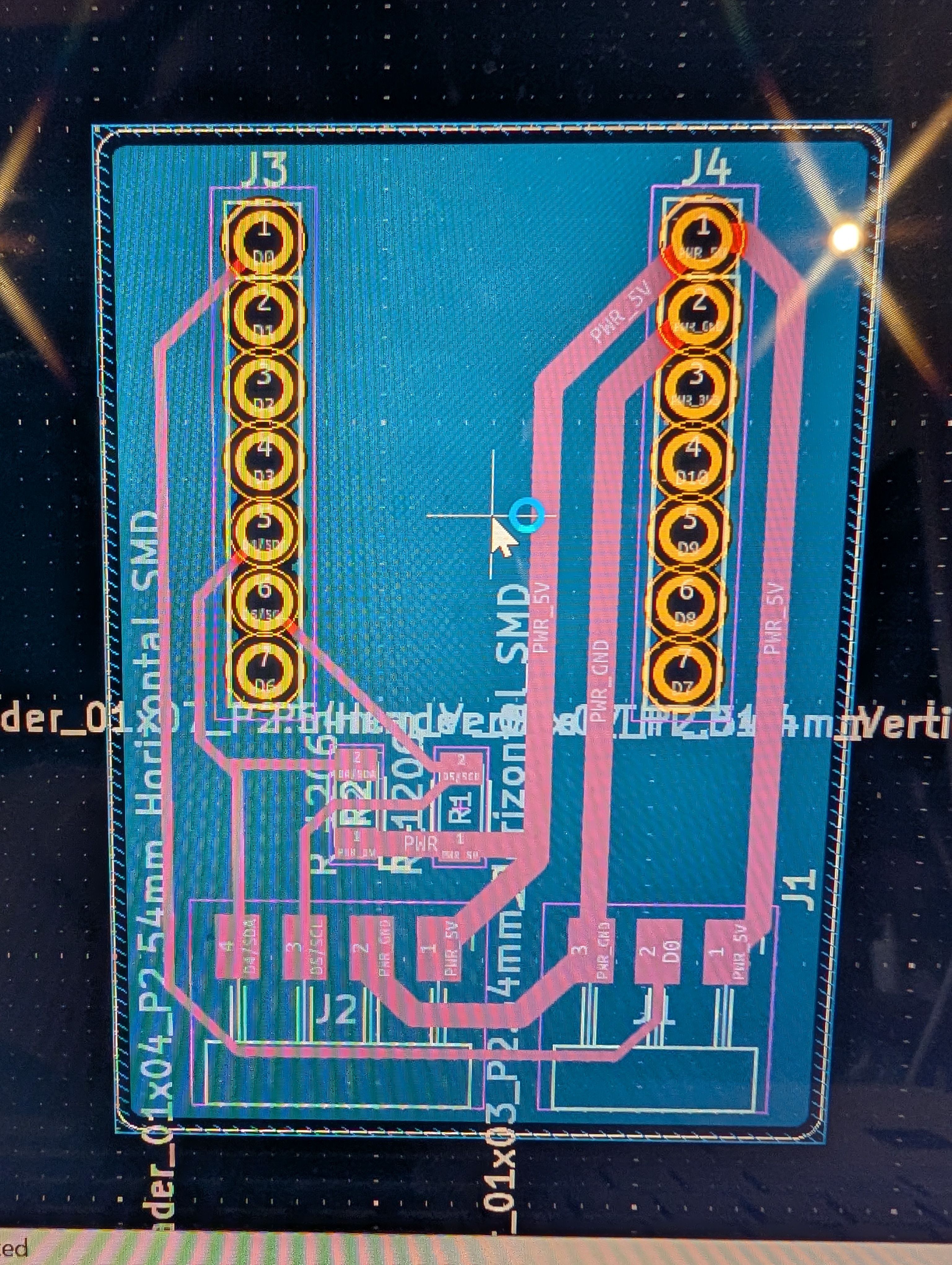
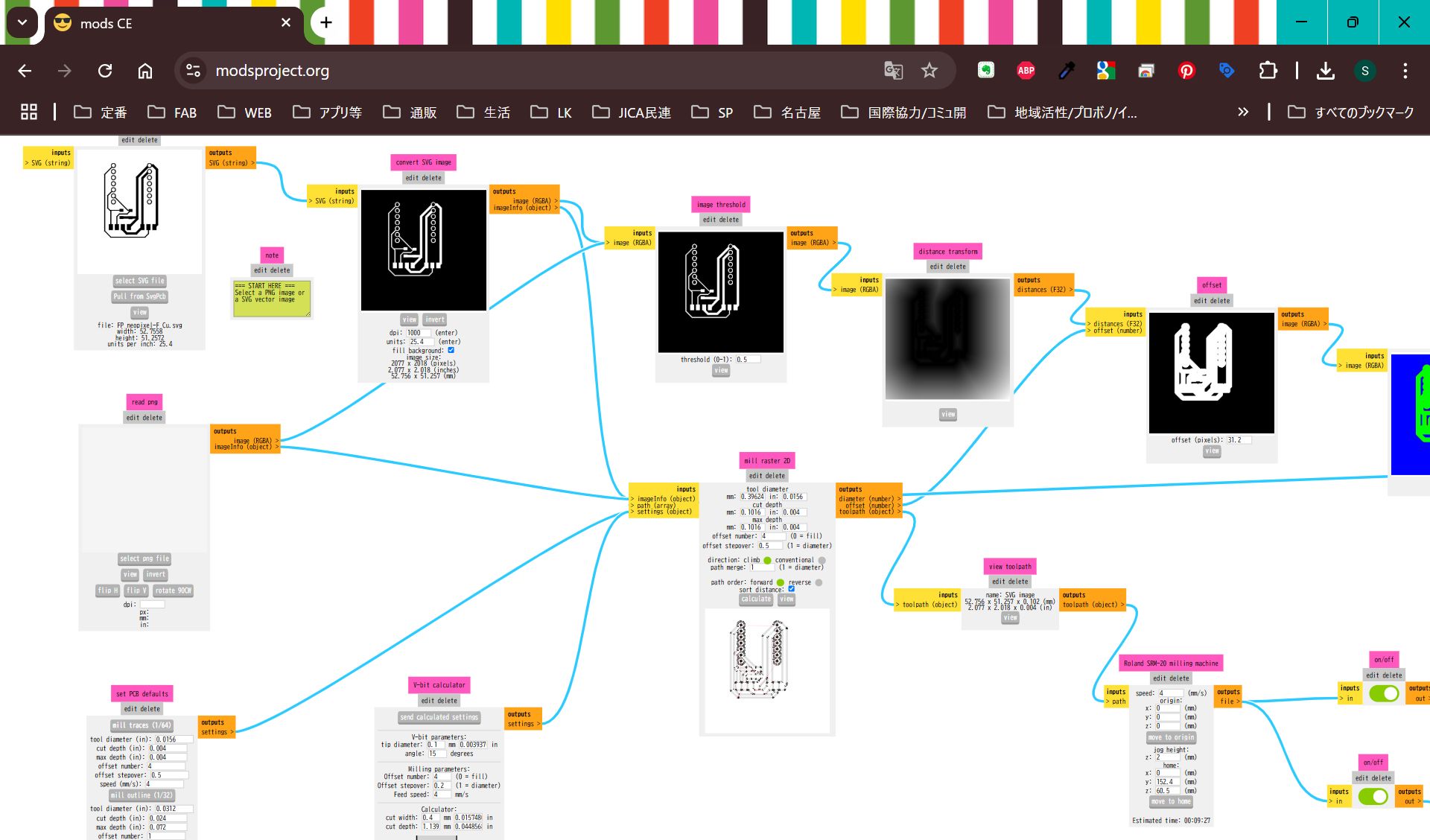
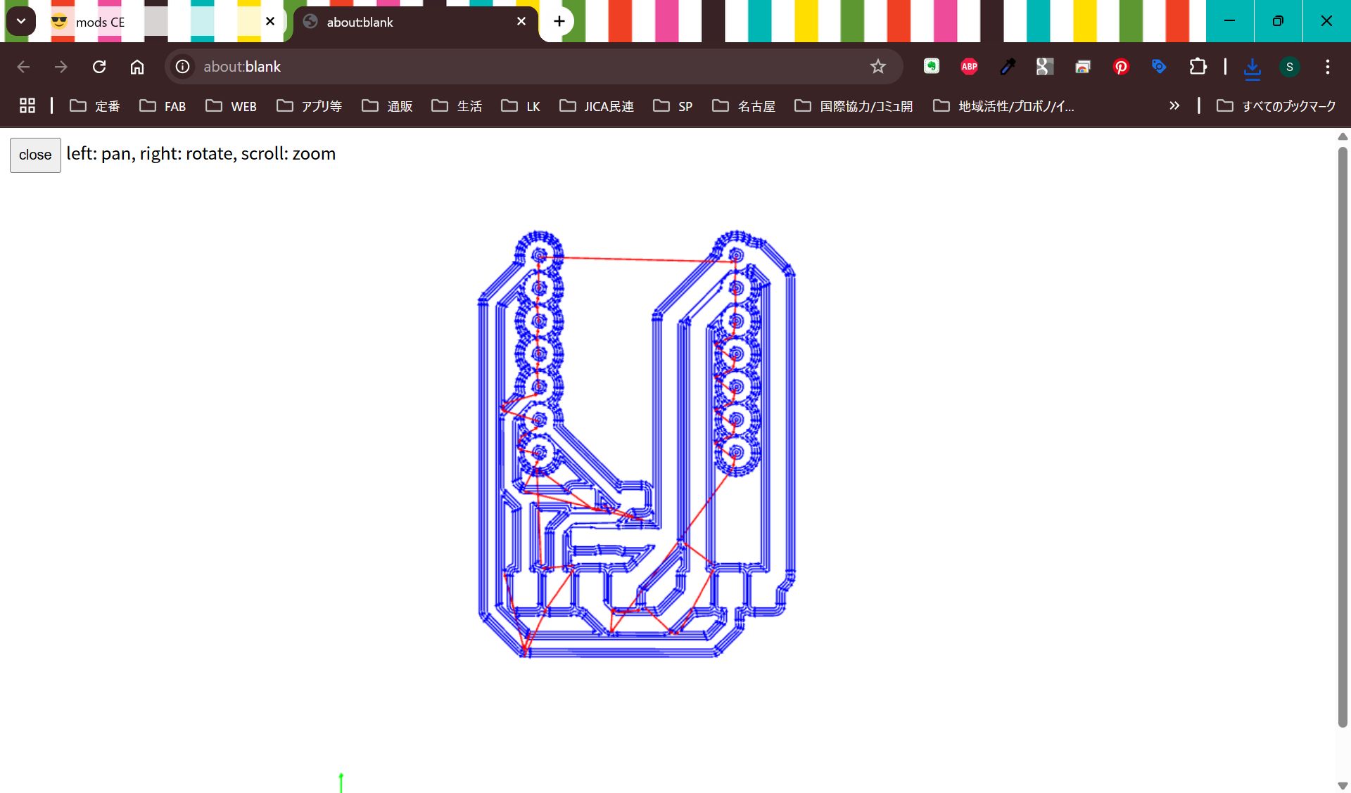
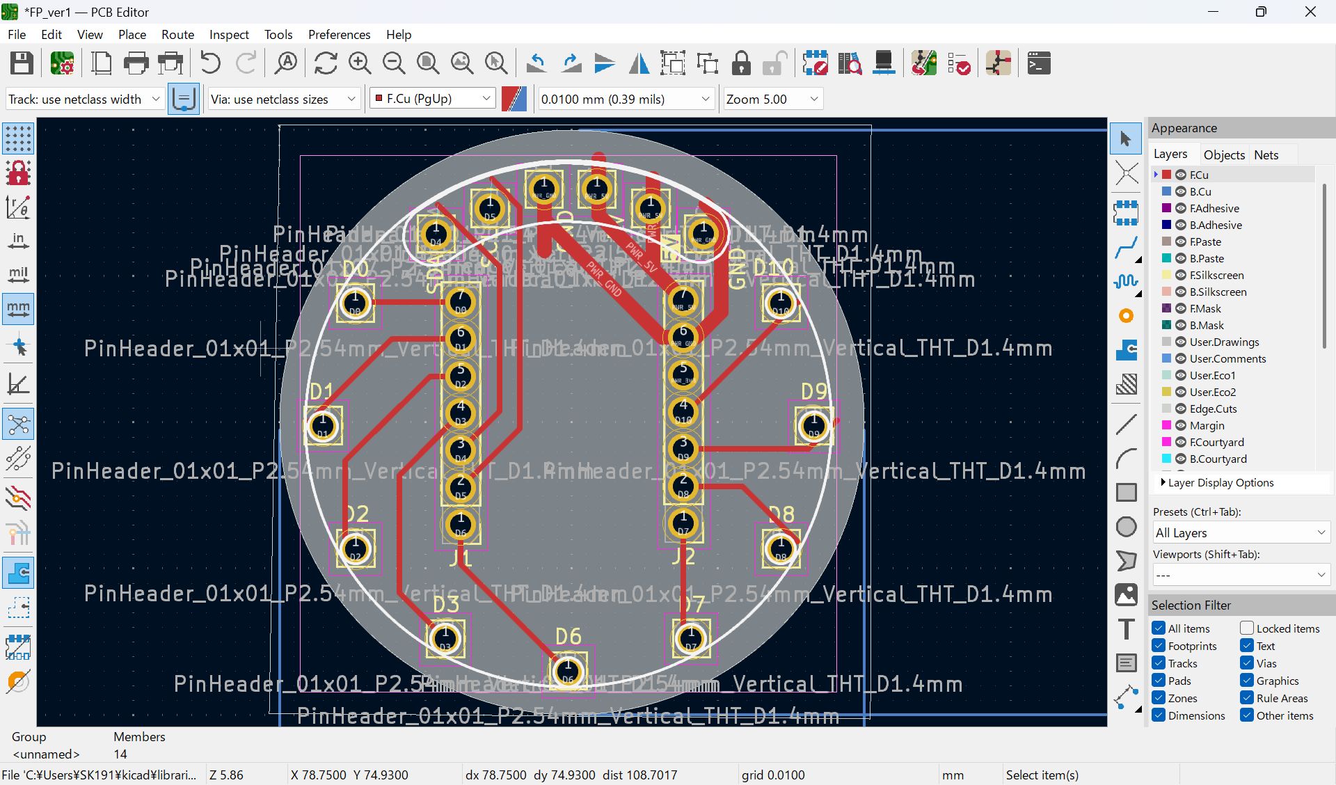
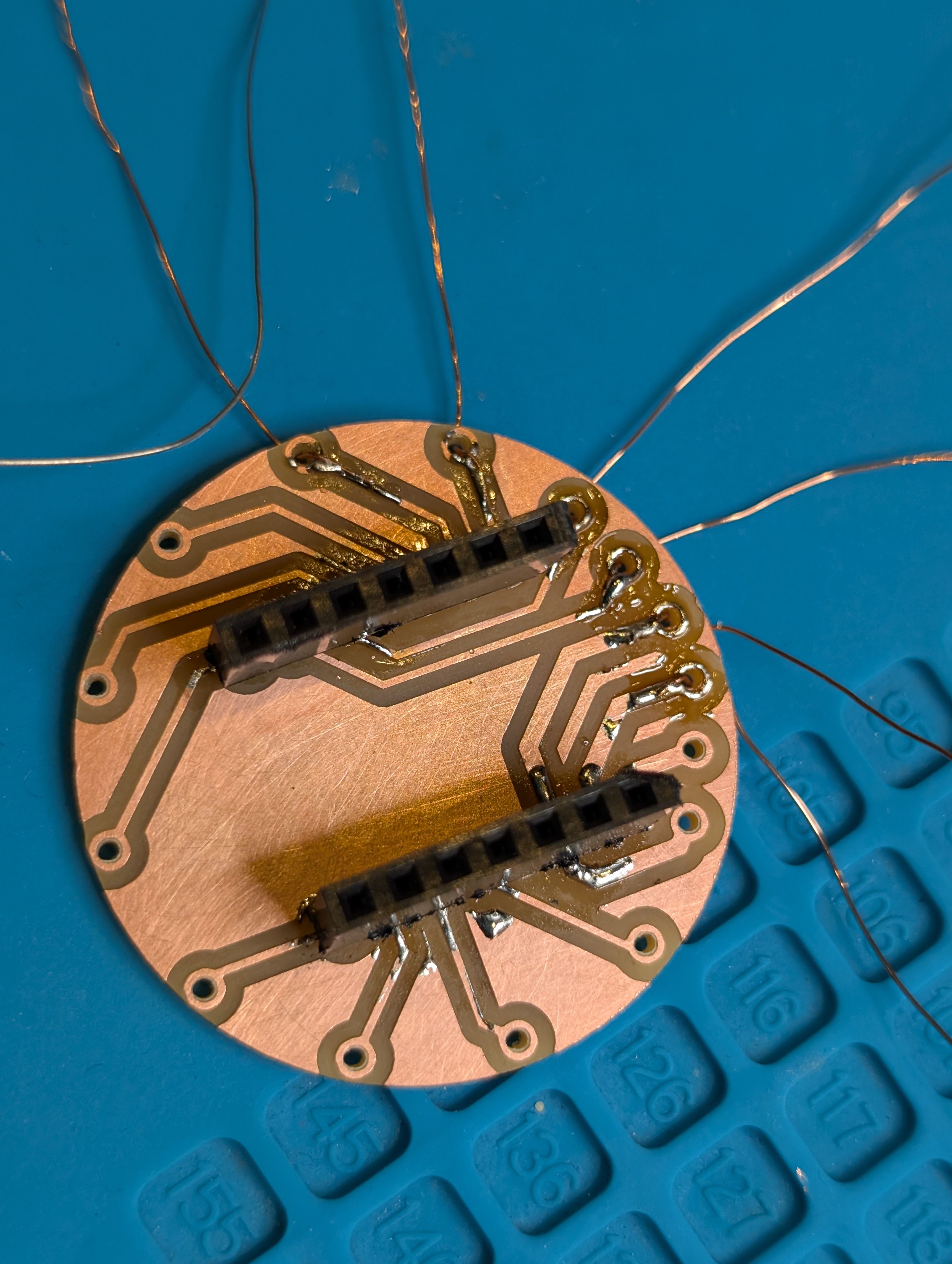
Make PCB fit for the case
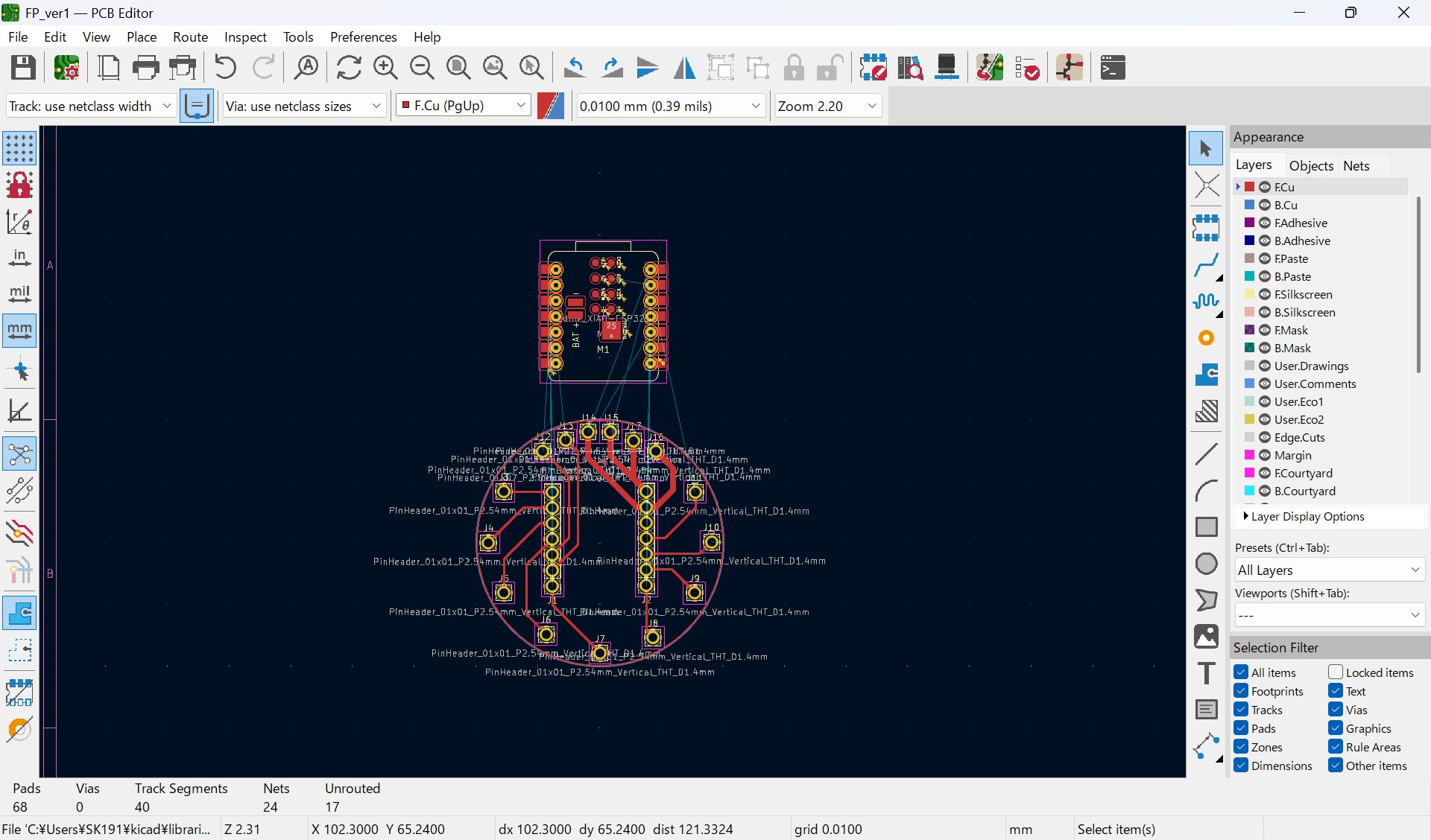
I mistook the pinout, and modified
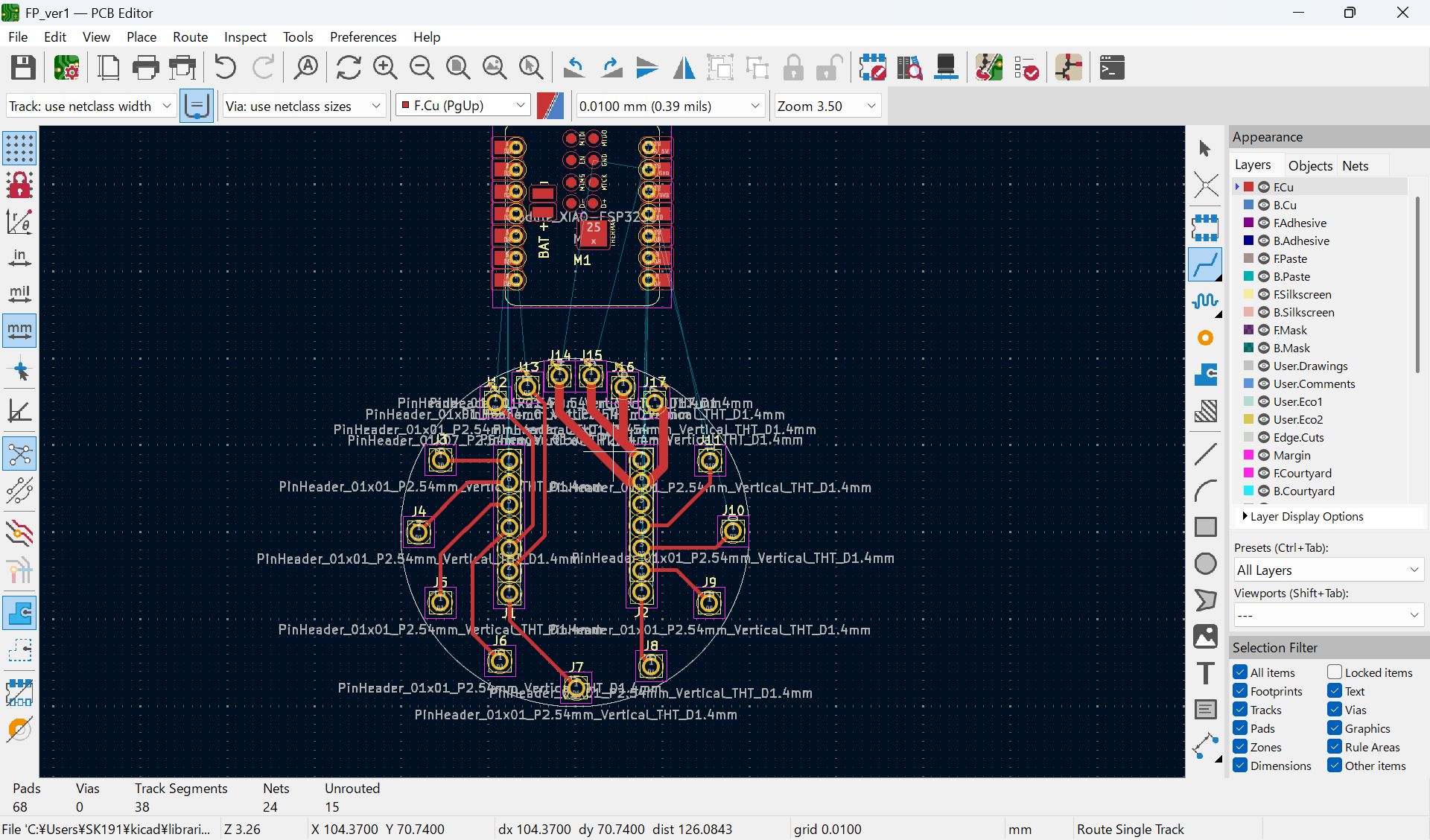
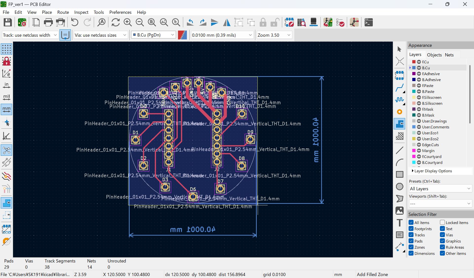
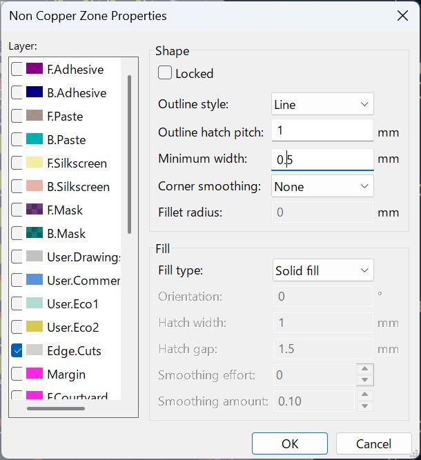
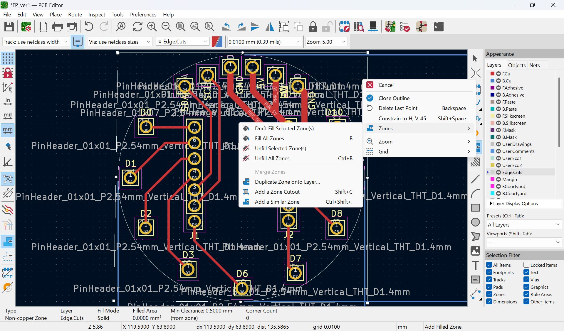
I haven’t documented how to set ‘Fill all zones’, I set as below before select fill all zone
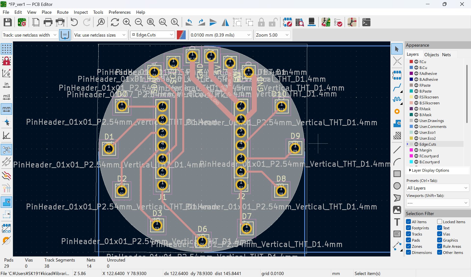
Modify hole cut line file
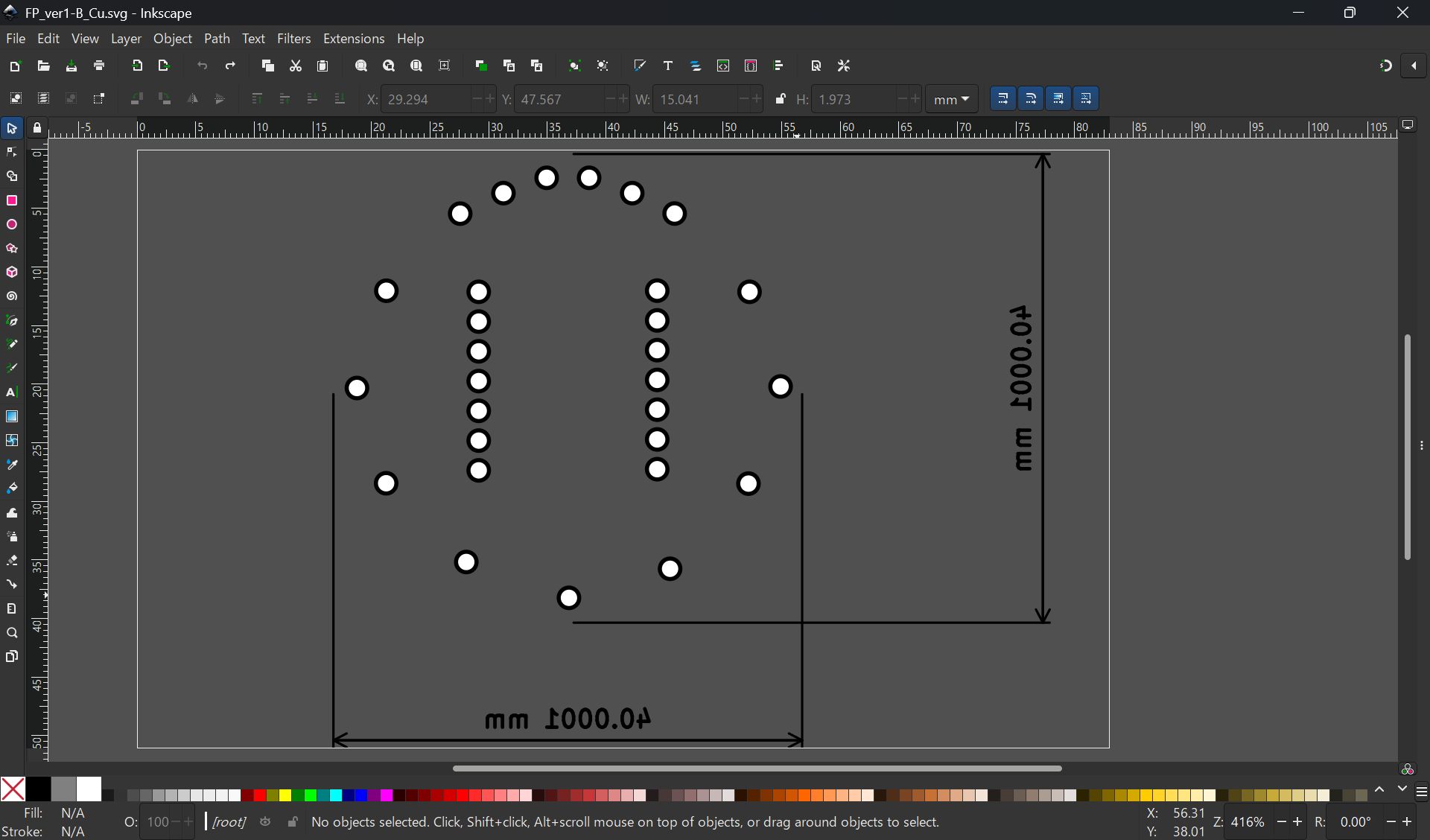
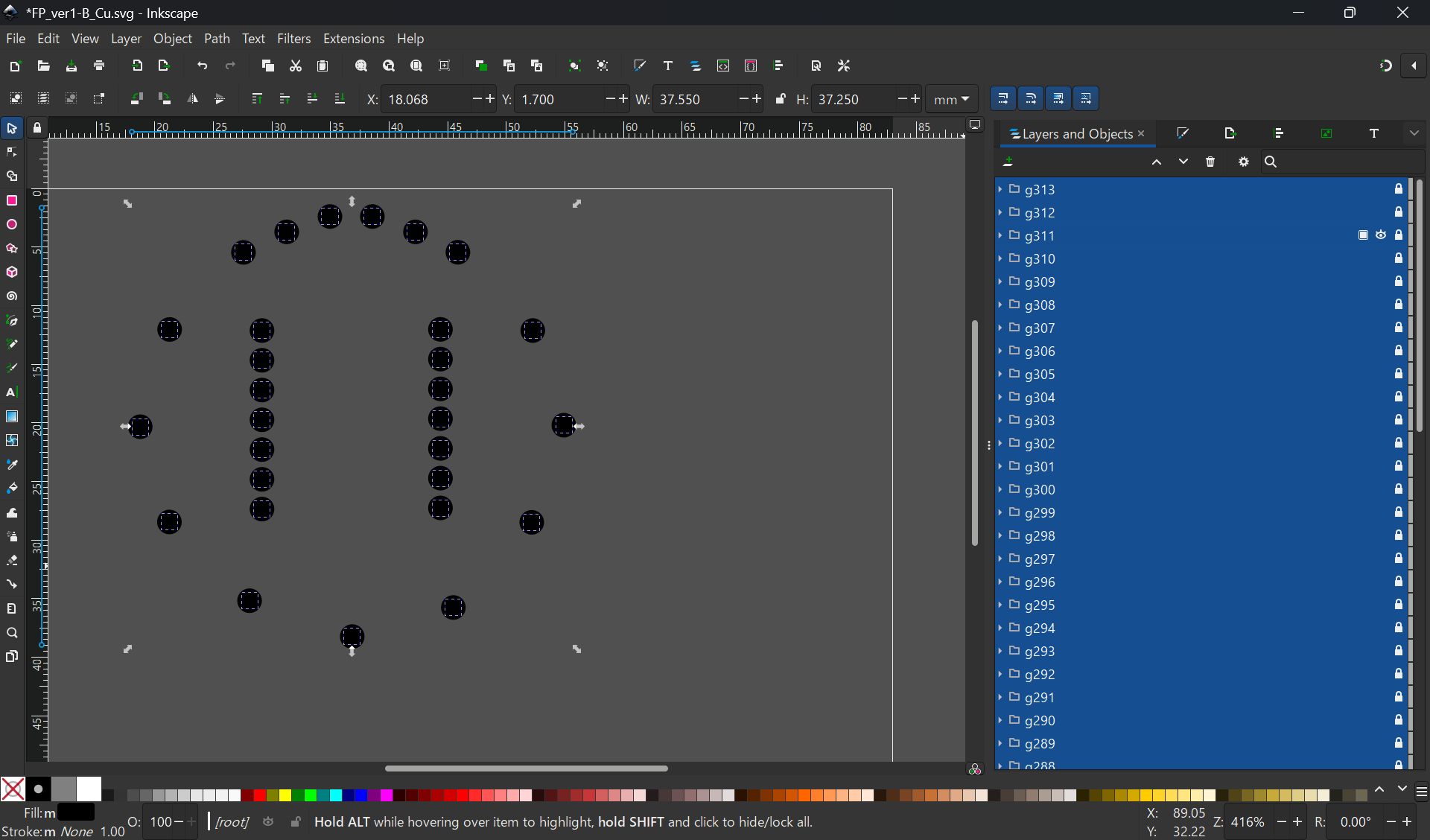
I import svg file from KiCad, but it was difficult to make it fit, so finally, I project the case face and made the svg image from Fusion, and import it in KiCad, and modified design.
*No invert for hole
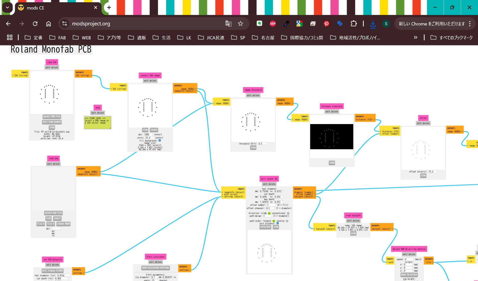
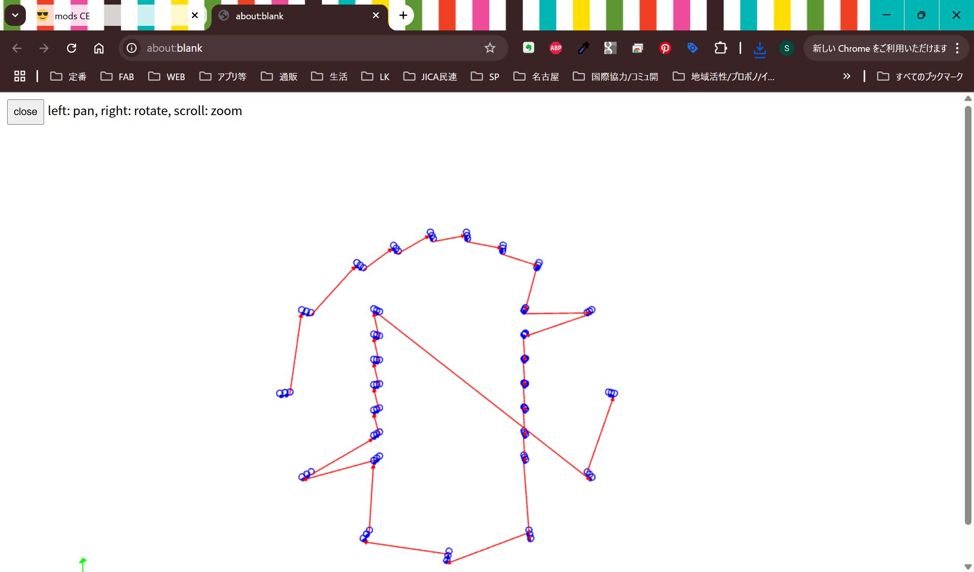
Cut it and assemble.
For the details, please see Week15 documentation.
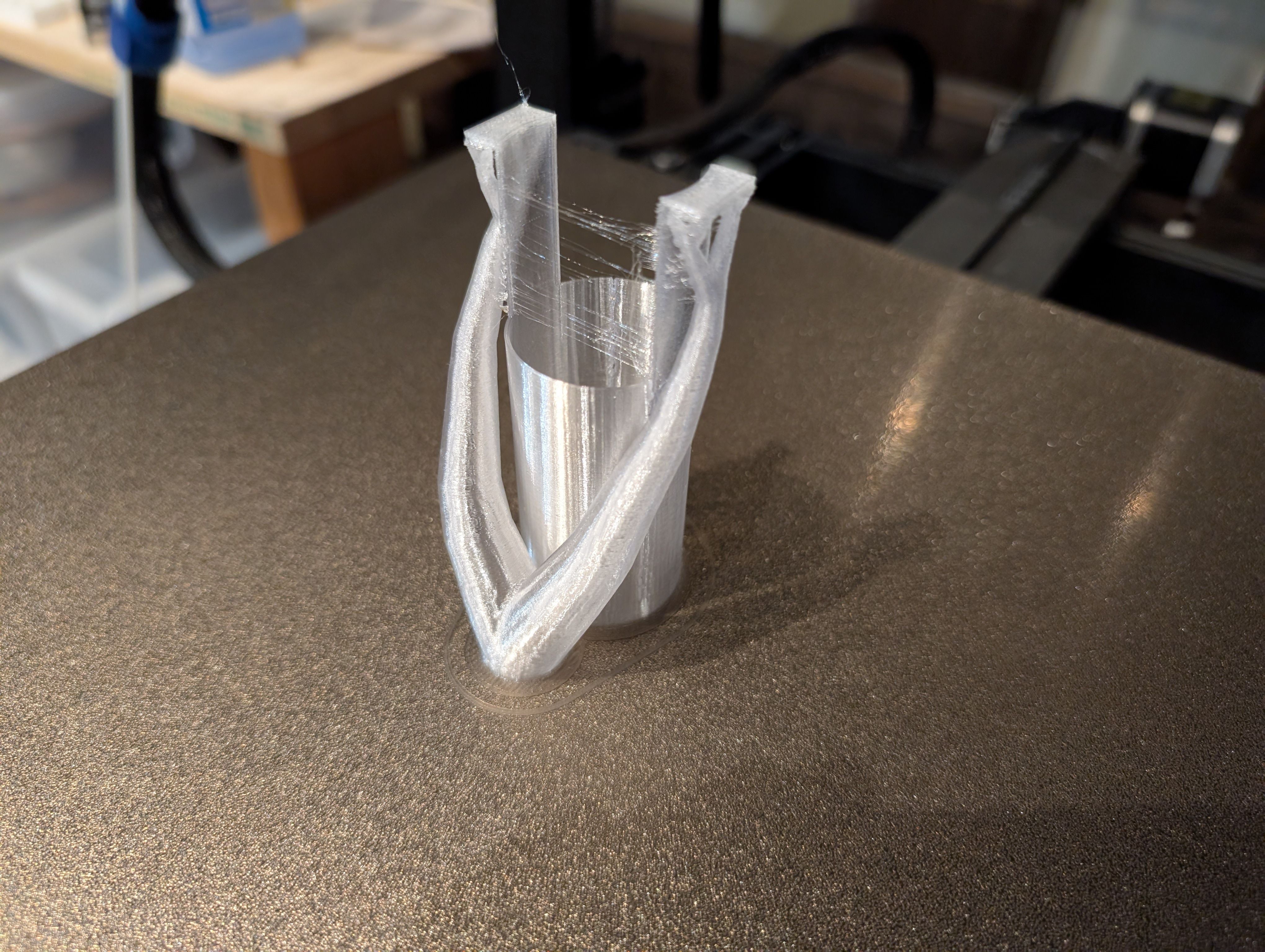
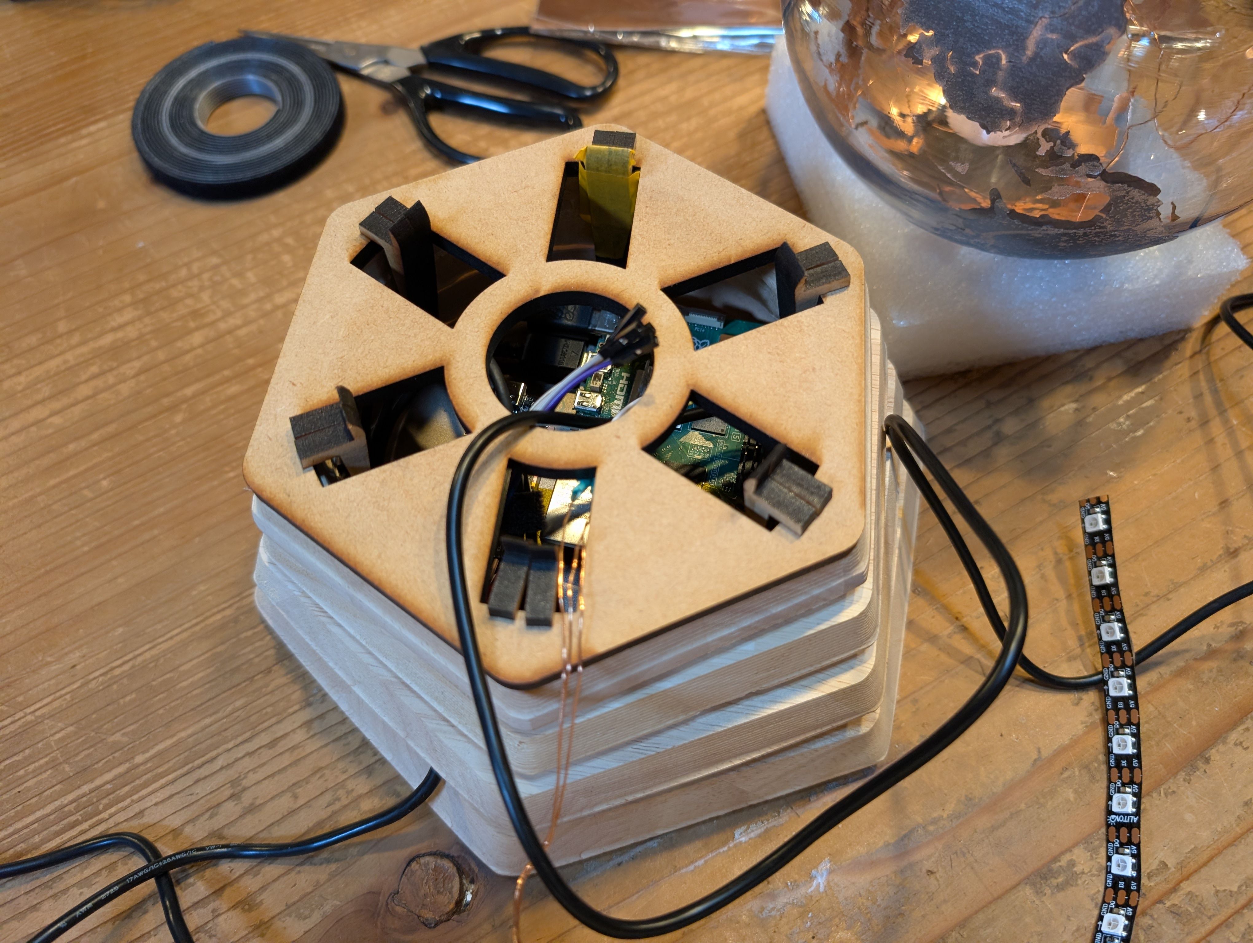
I also made a support part with 3D printing to fix this case in the middle of the
globe.
I tried to make it thin with flexure function and fit to silicon base part.
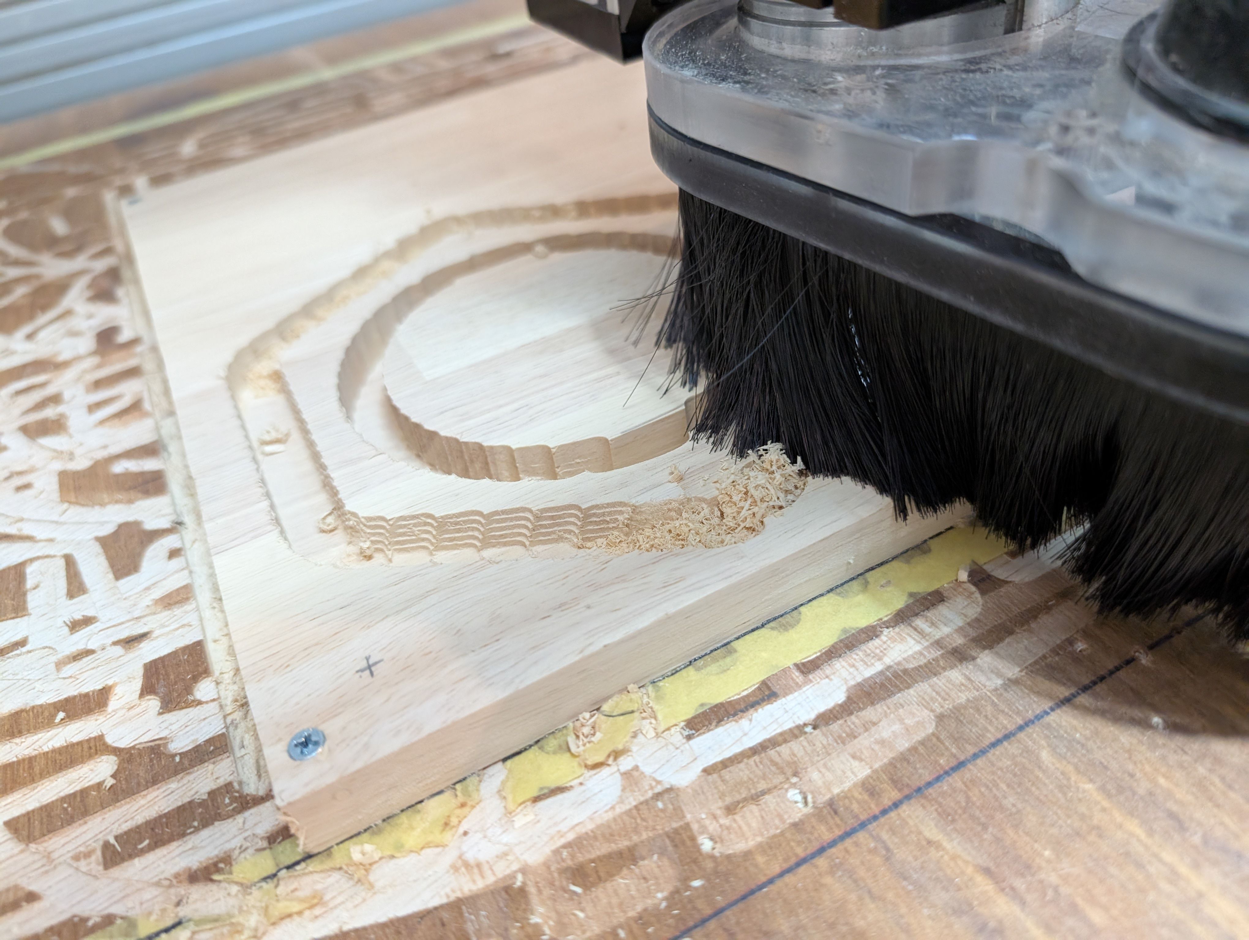
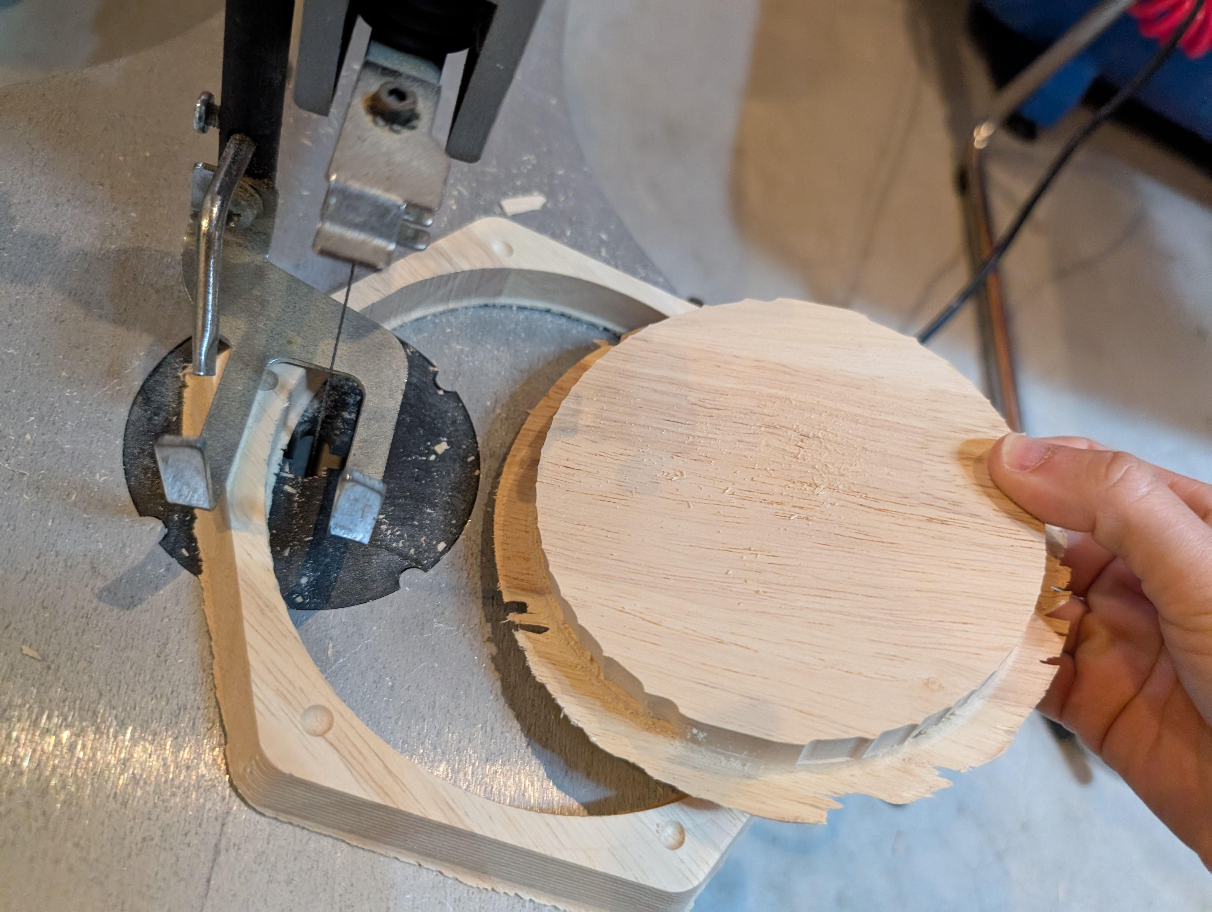
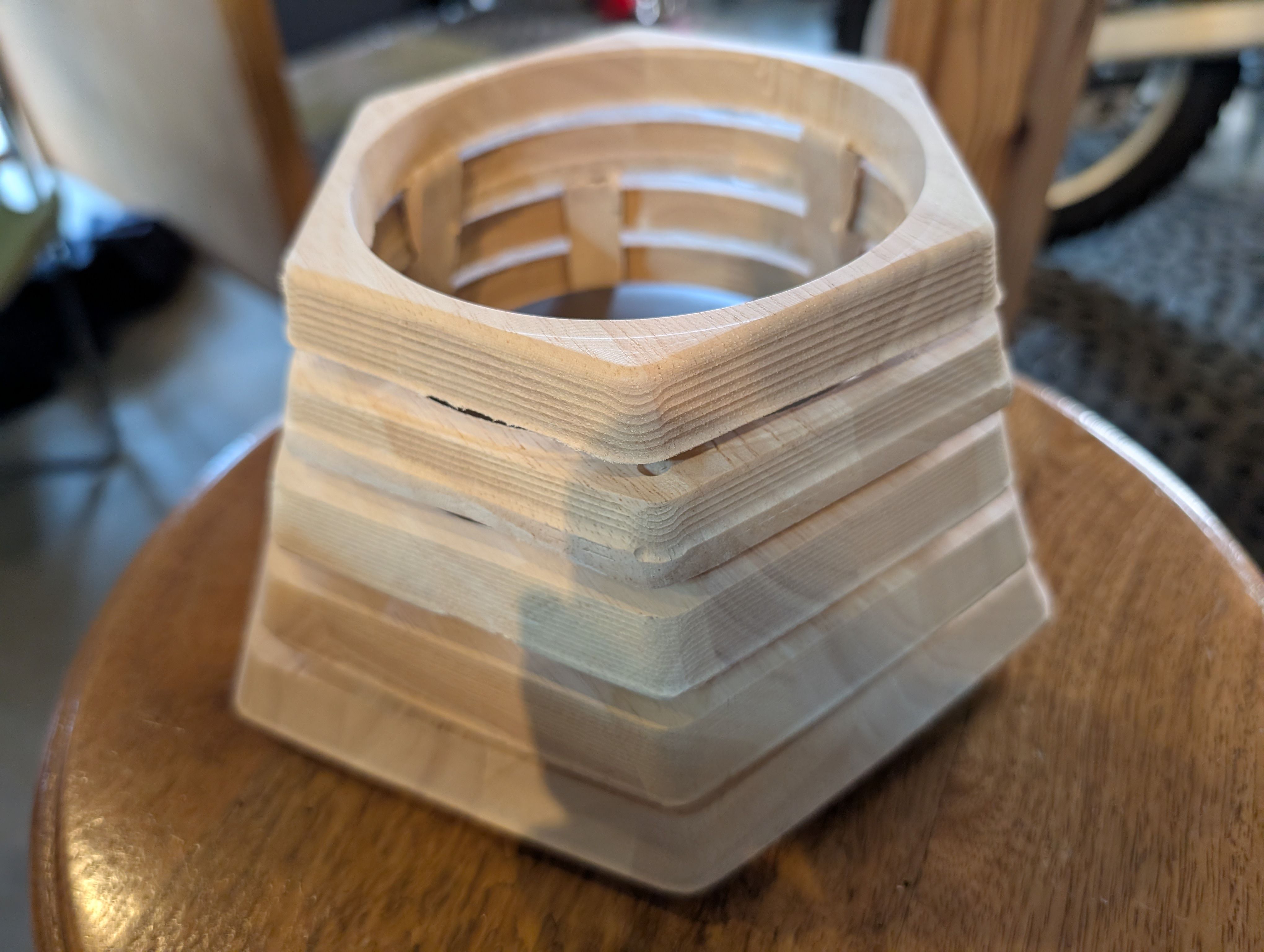
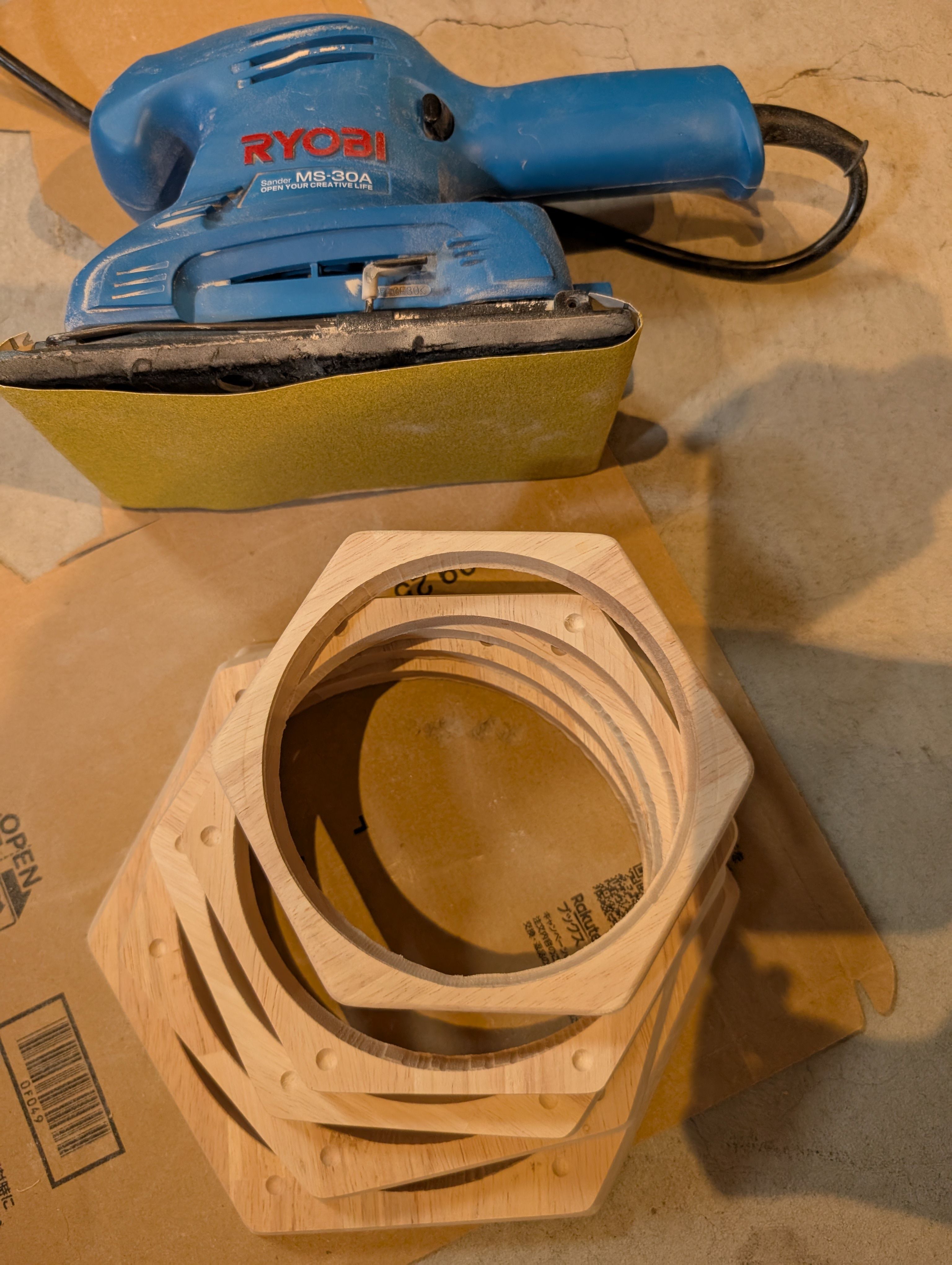
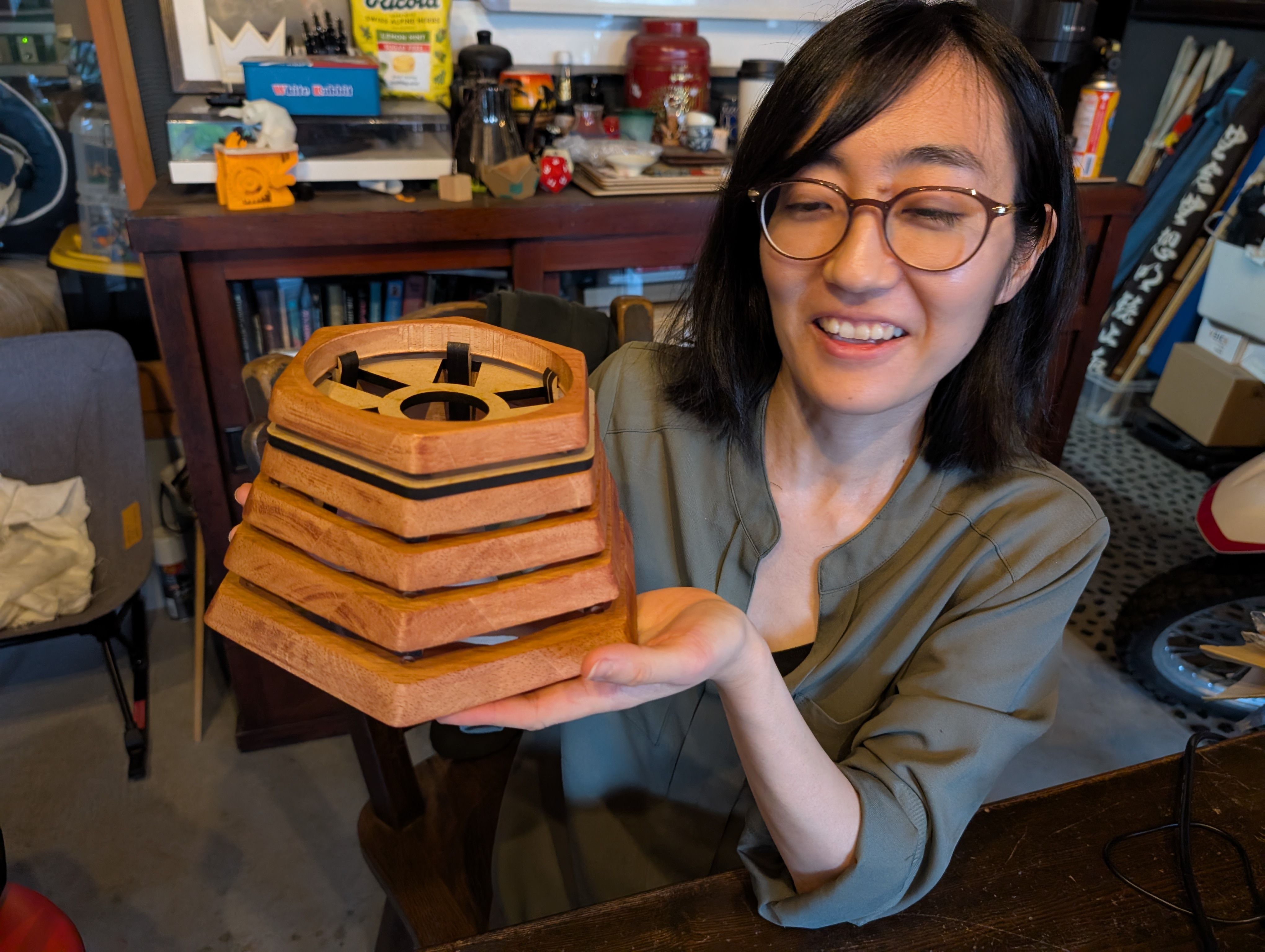
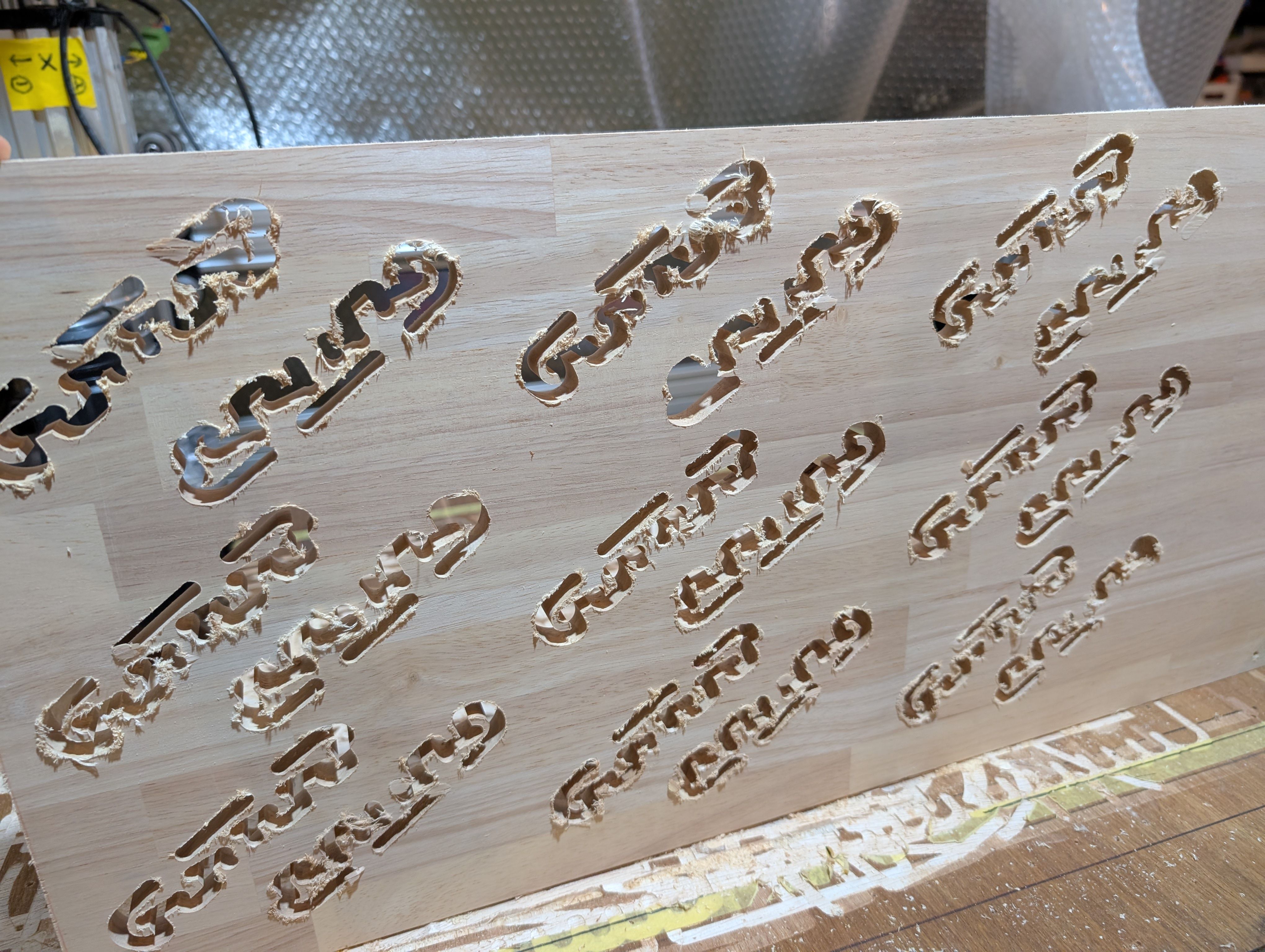
Base Parts - Wood Milling(Week 16)
Design (Fusion)
Initially, I was going to make a box shape and cut it out from a block of wood,
However,
- It would be a waste to dig out the entire center parts of wood (= unusable later)
- Digging takes too much time
- It is difficult to find a large block of wood
In addition, due to the problems of heat exhaust and image projection of the
projector,
I considered a method that would have a good design but also leave a gap between
the projector and the wood.
As a result, the following design was obtained.
Tool Path
Path requirement: Set up a tool path to cut out a block from a piece of wood while
cutting it.
In this process, I had the most difficulty in finding the best way to
create the tool
path suitable for the above.
Since I needed to cut out the tree, not just dig it
out, I spent a lot of time trying
to figure out how it should be set up.
Fusion or VCarve?
I couldn't find documentation to do both milling and cropping, so I went back and
forth
between the two softwares to find a way to set it up successfully. As a result, I
used VCarve to set up the settings.
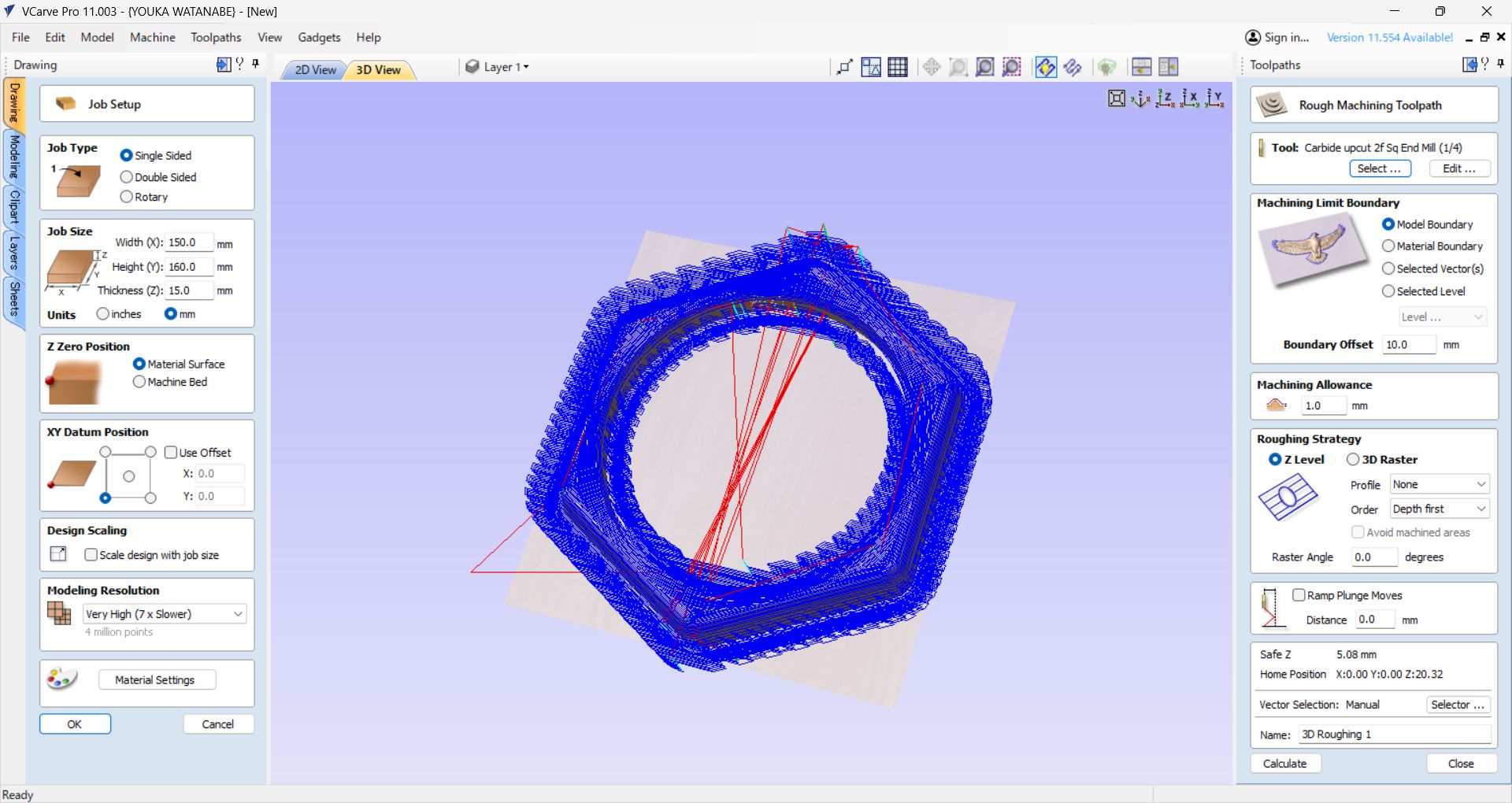
Settings in VCarve
Toolpath:
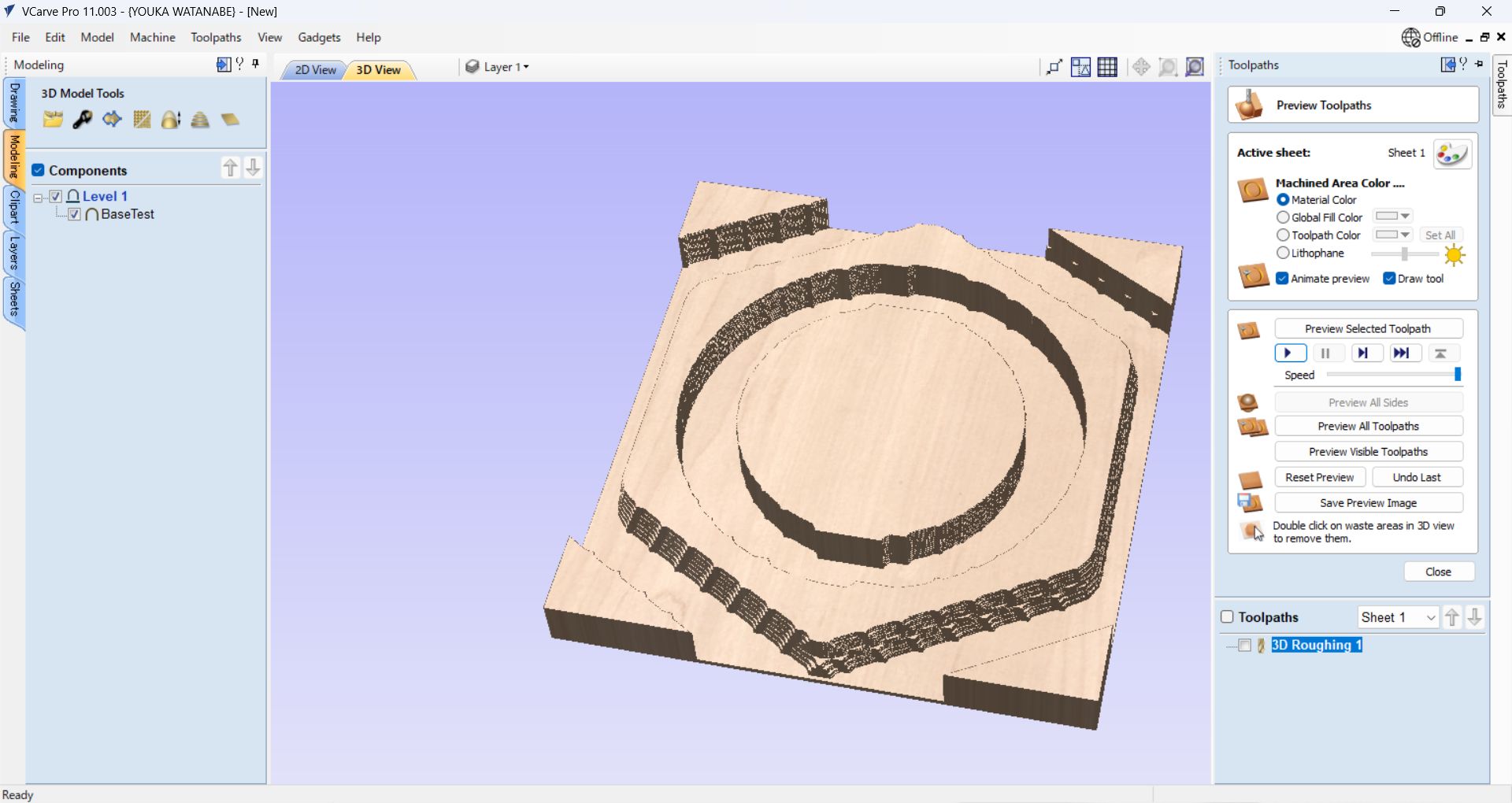
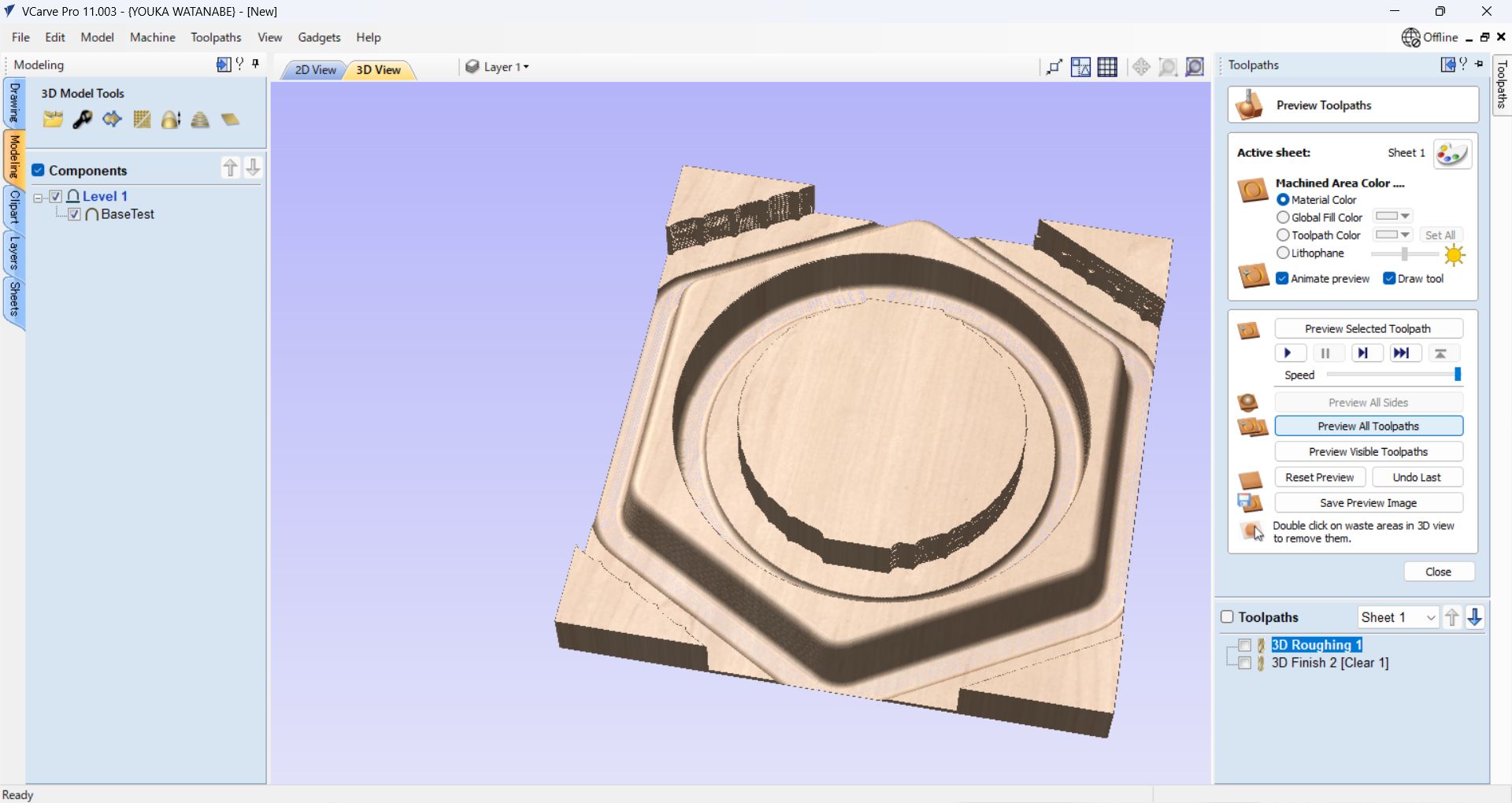
"3D roughing" for rough cut
"3D Finishing" for finish cut
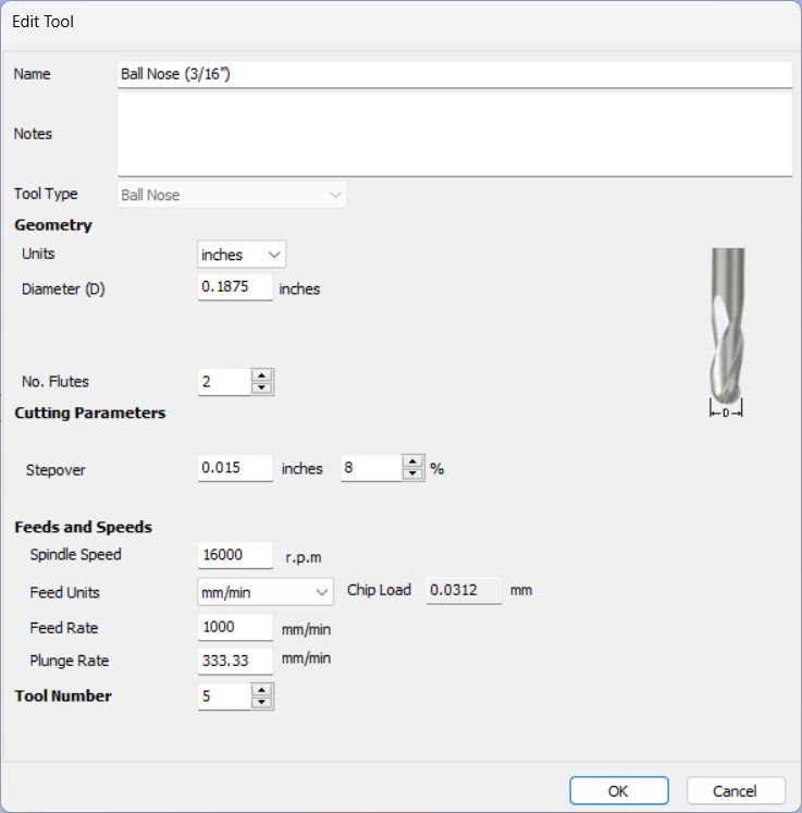
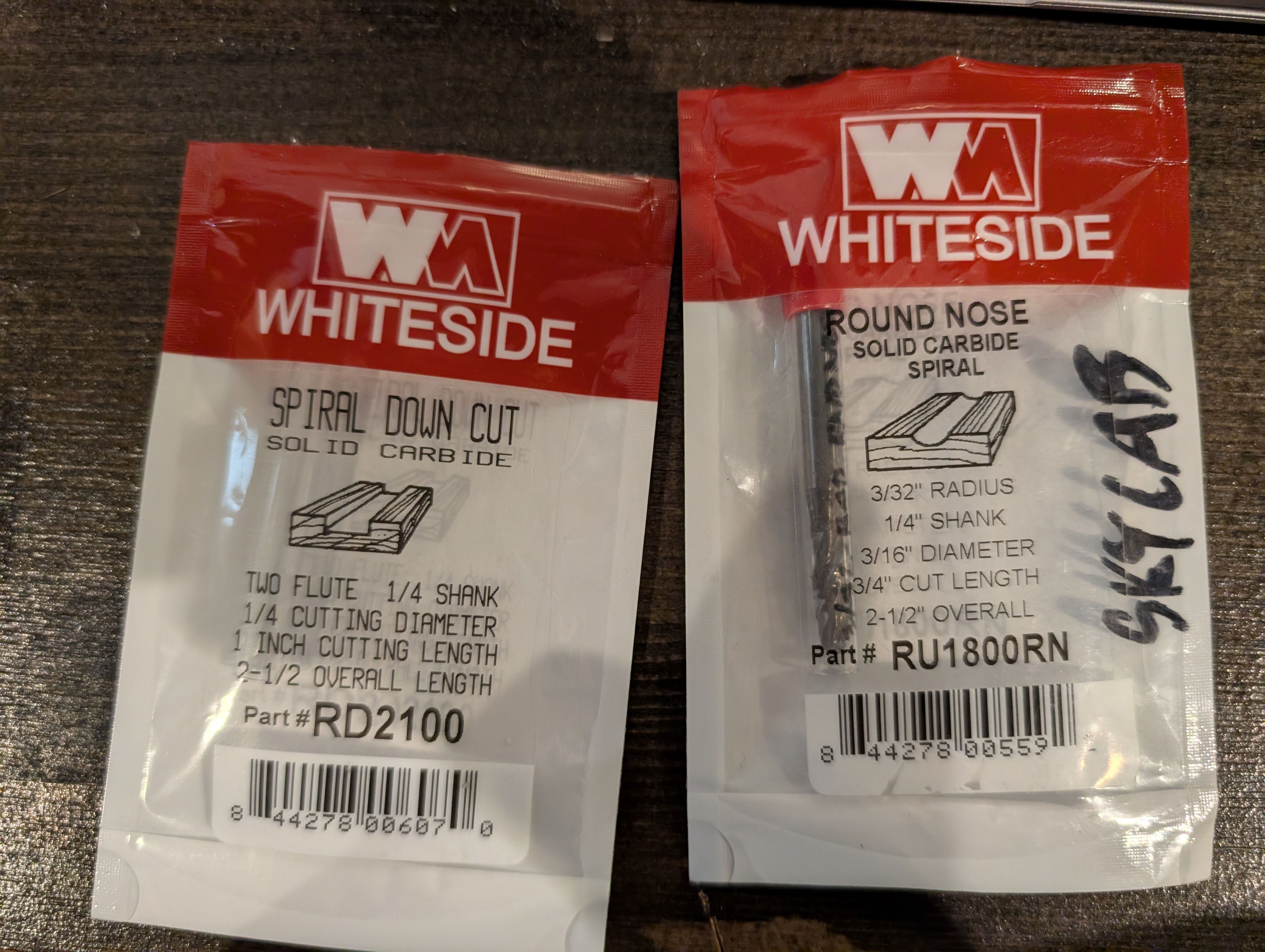
Tool:
Roughing:
Spiral
Down Cut 2 Flute, 1/4 shank, 1/4 cutting diameter
Finishing:
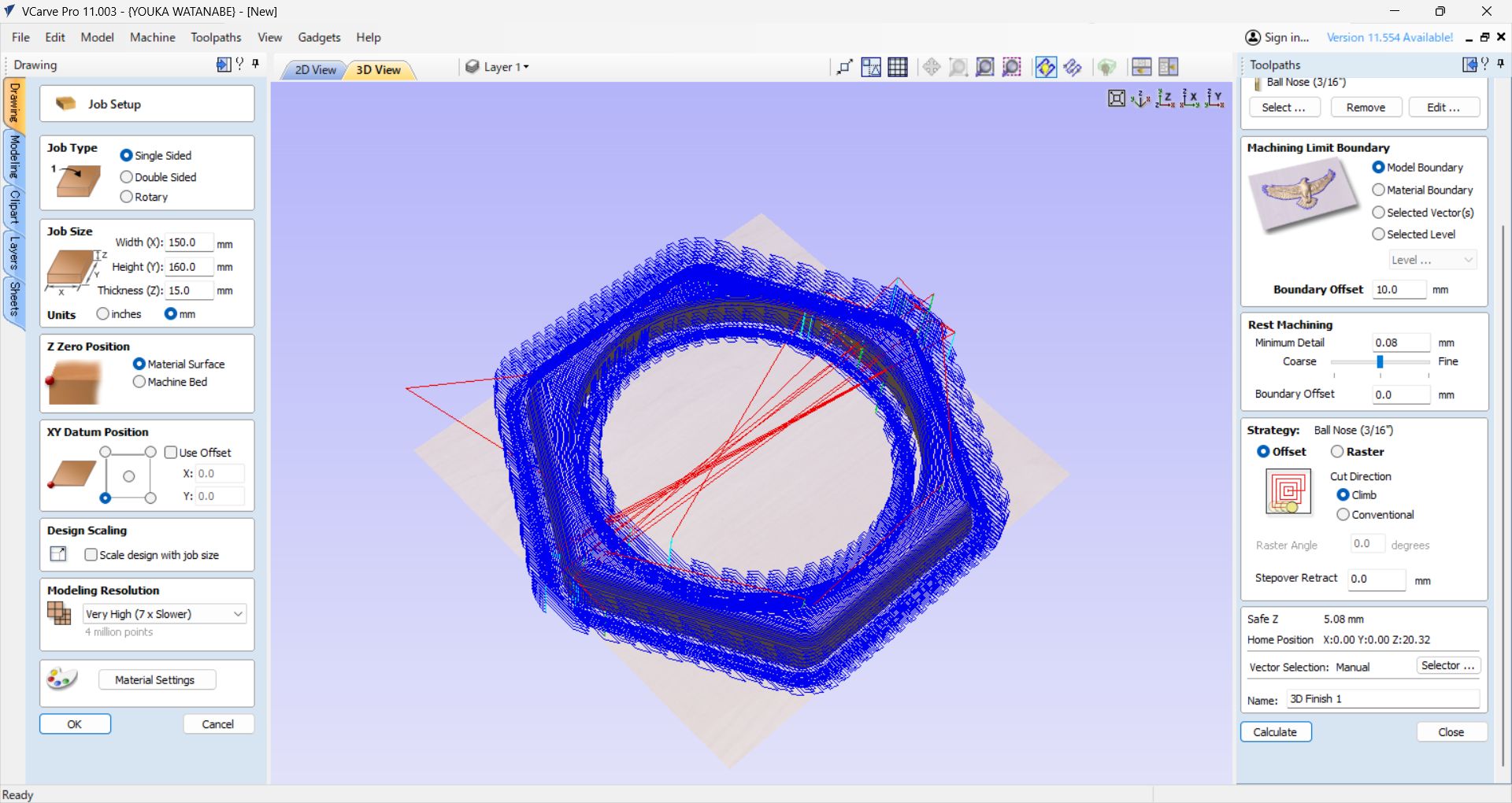
Round Nose , 3/32 radius, 1/4 shank, 3/16
diameter
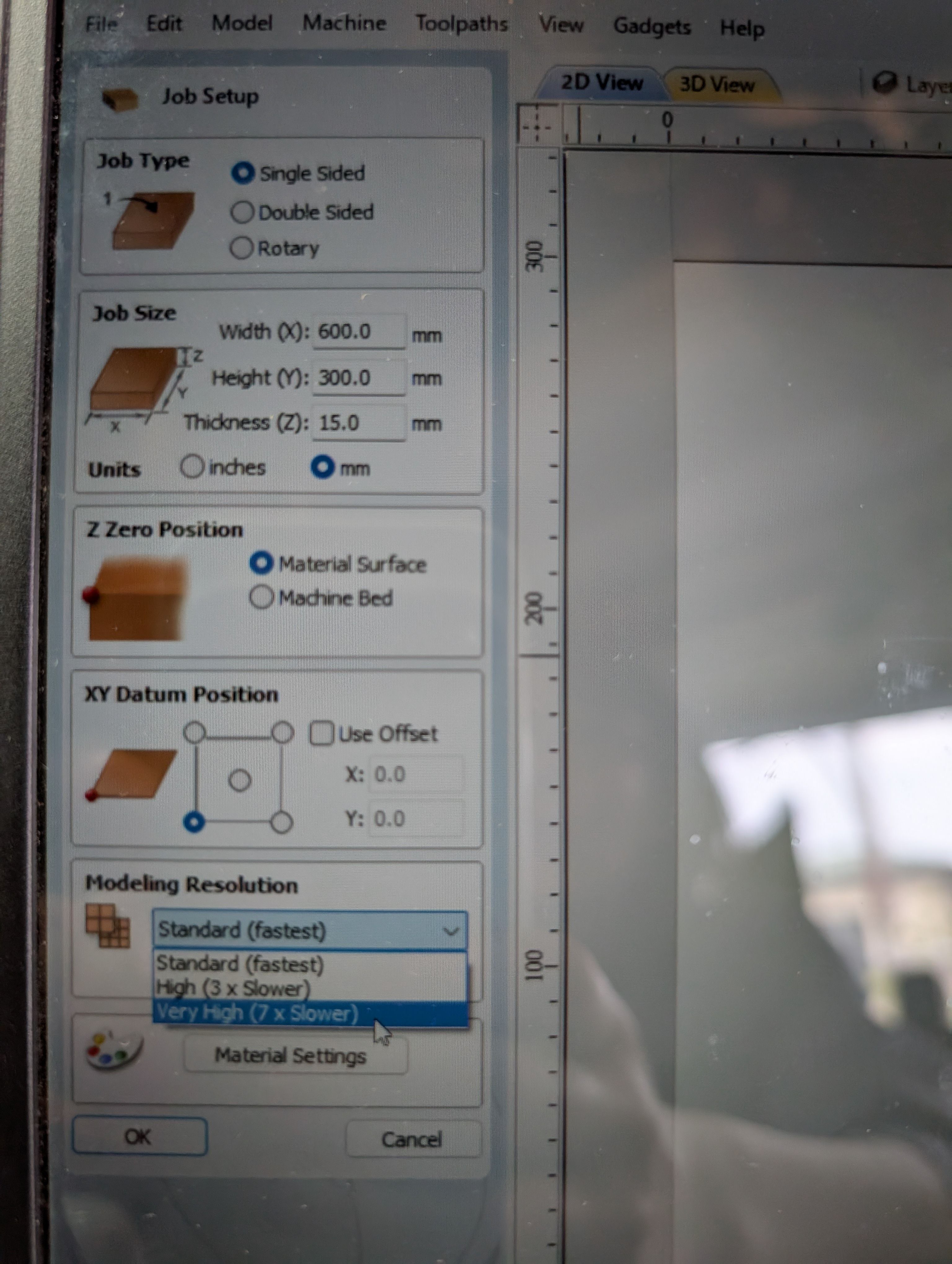
Job Setup
Single sided Job size: set same as material size
Offset X,Y = 0,0
Modeling Resolution: Very High
Material Settings: Canadian Maple
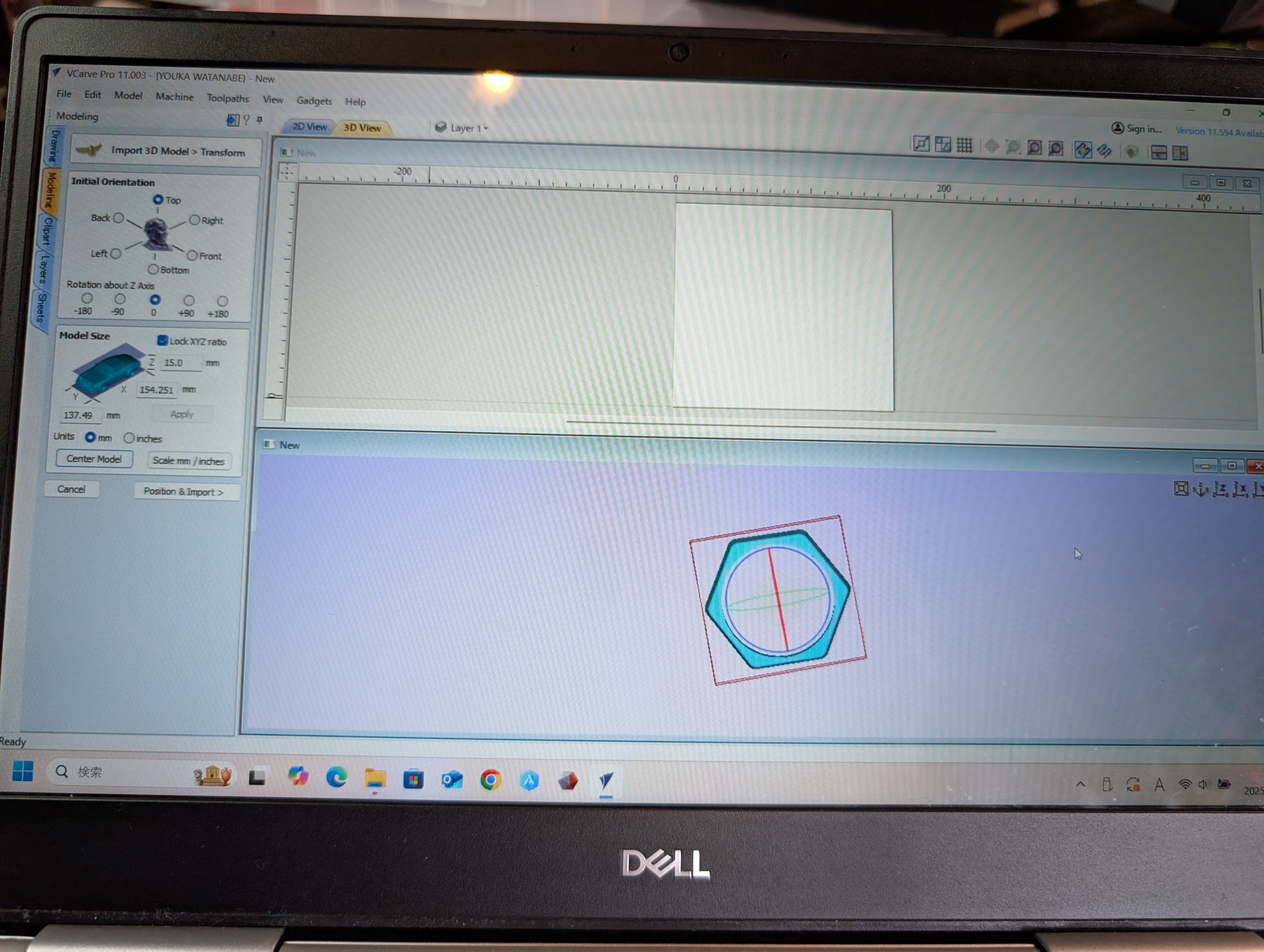
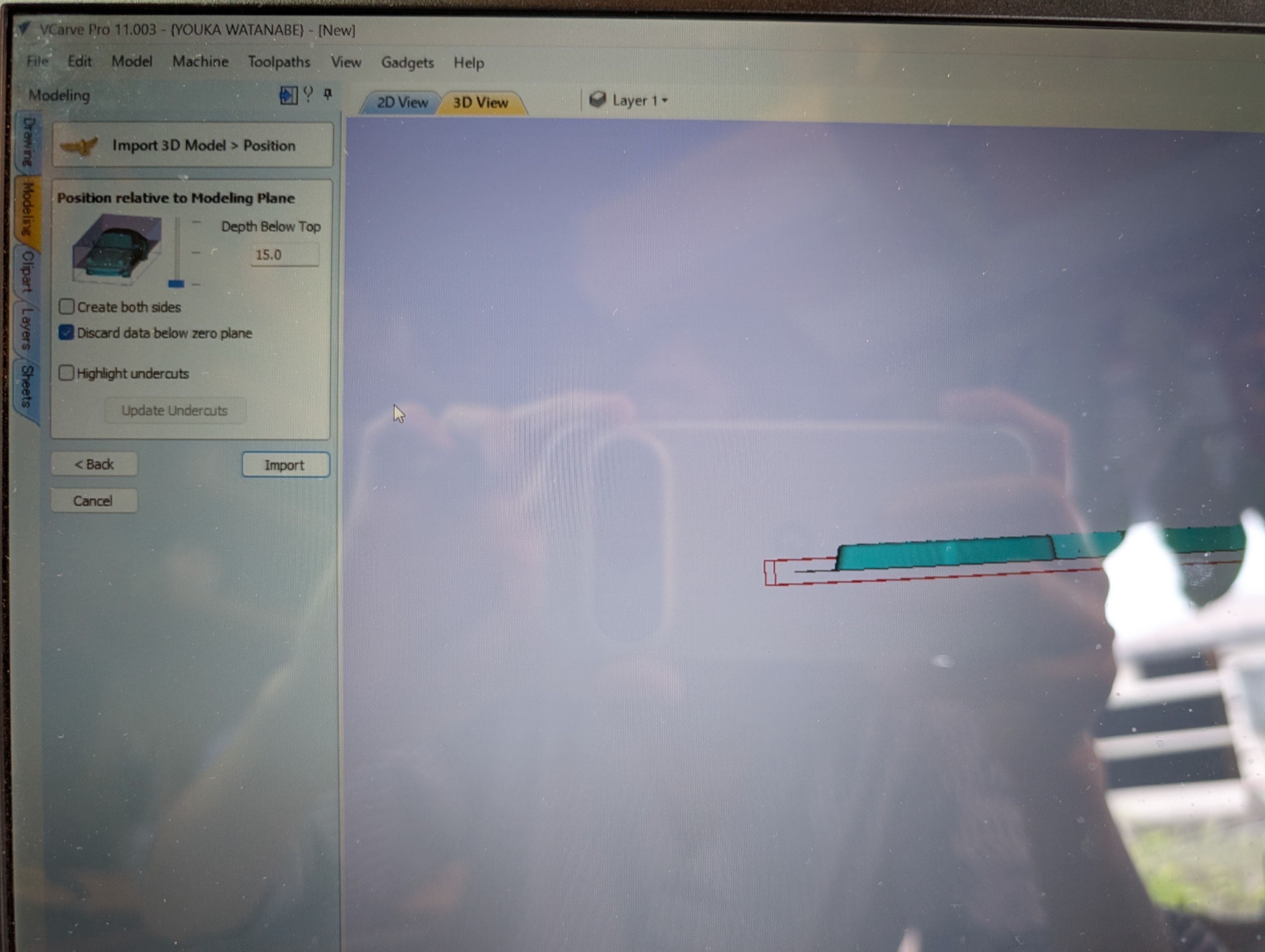
Import 3D Model from "Import 3D model" menu in "Modeling" tab
Center model
Position relative to modeling Plane - Depth Below Top: same as material
thickness(since
this is not double sided design)
Setting for Roughing tool
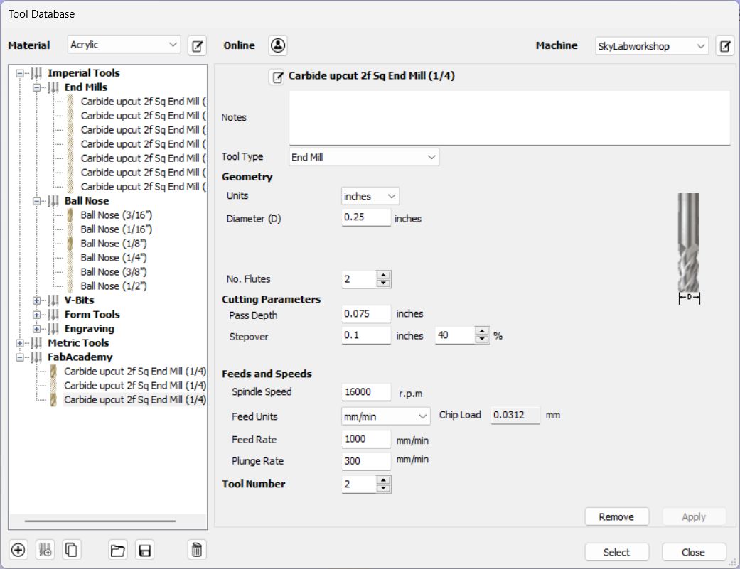
Setting for Finishing tool
Roughing path setting
Machining Limit Boundary: Same as above.
Model Boundary, Boundary offset: 10.0mm(Bigger than tool diameter(6.5mm))
Finishing path setting
Machining Limit Boundary: Model Boundary, Boundary offset: 10.0mm(Bigger than tool
diameter(6.5mm))
Model Boundary, Boundary offset: 10.0mm(Bigger than tool diameter(6.5mm))
Strategy: Offset, Cut Direction: Climb
At first, when I set the Model Boundary, an error occurred when generating toolpaths.
The error was resolved by using Material Boundary, but Material Boundary has
many
milling parts, which is wasteful and time-consuming.
As a solution, I set a
Boundary Offset of the tool width (∔α) in the Model Boundary and
was able to cut successfully.
CNC
As with Machining, the following steps are used in OpenBuild for cutting.
After RoughCut is finished, it is necessary to replace the tool for Finishing.
The XY axis is not changed, but only the Z axis is reset (as in SRM). It is
necessary
to set z-axis correctly (see below) since it cause CNC may or may not cut out the
wood.
Safety (Protect Eyes and wear mask)
In some cases, it is necessary to fix the part to be cut with screws.
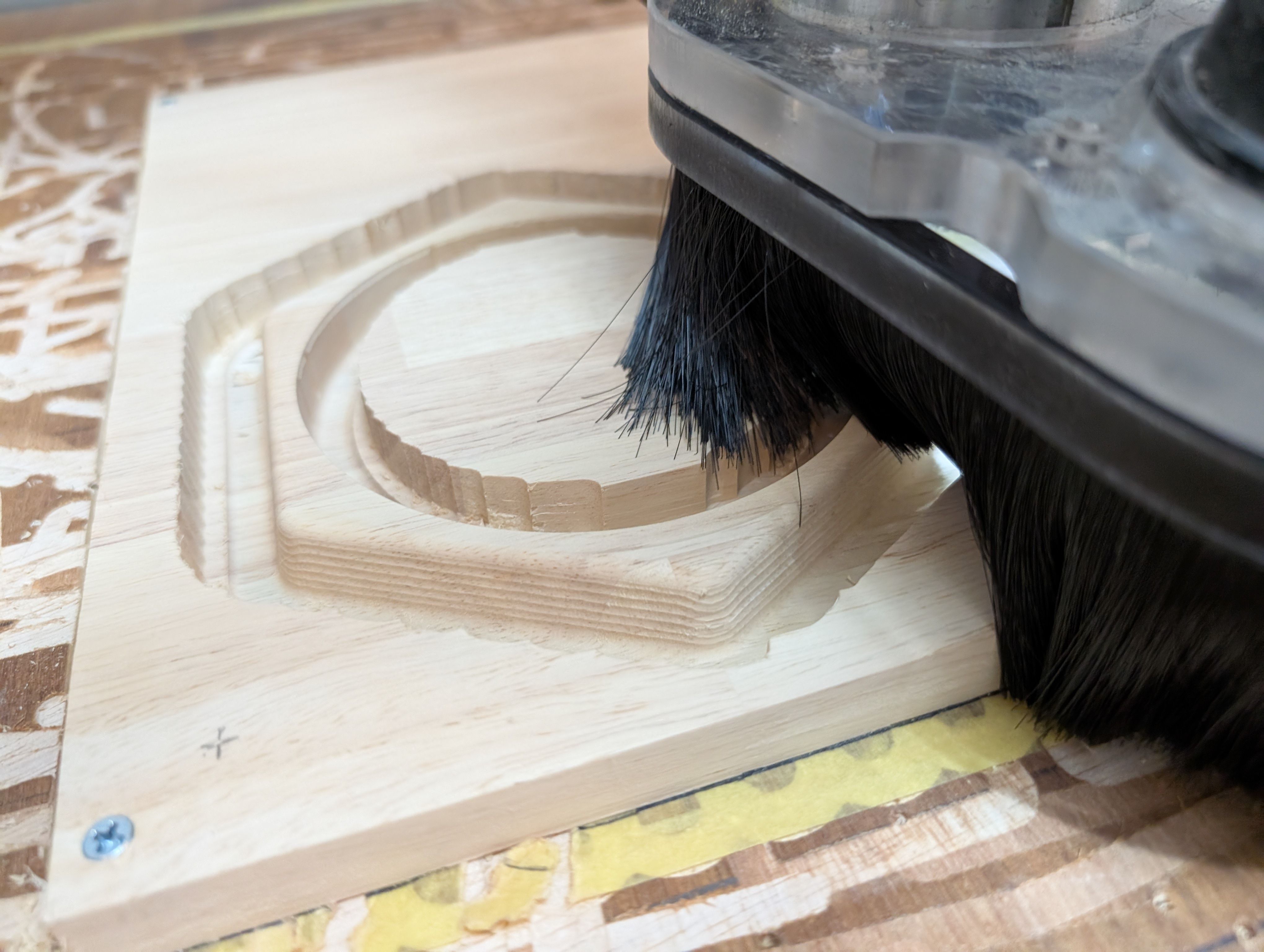
Finishing
Requirement: Smooth Finishing
At the time of scraping, the surface was generally finished smooth.
However, some of the bottom surface remained and was not separated from the wood,
resulting in a process of cutting and sanding the remaining parts with a thread saw.
(If the Z-axis is not set correctly, it may or may not be able to be cut.)
Result of assembly
For the details, please see Week16 WildCard page.
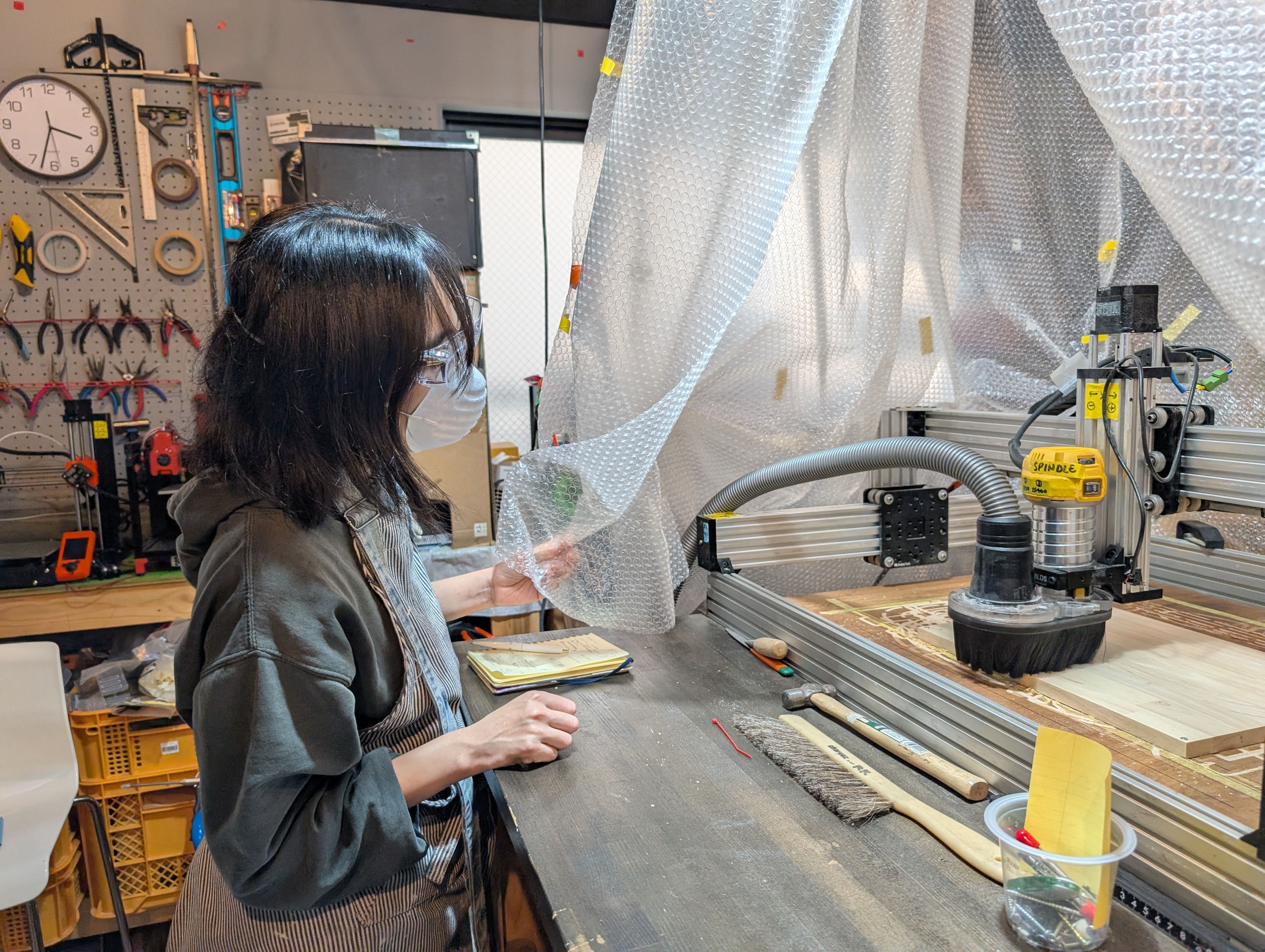
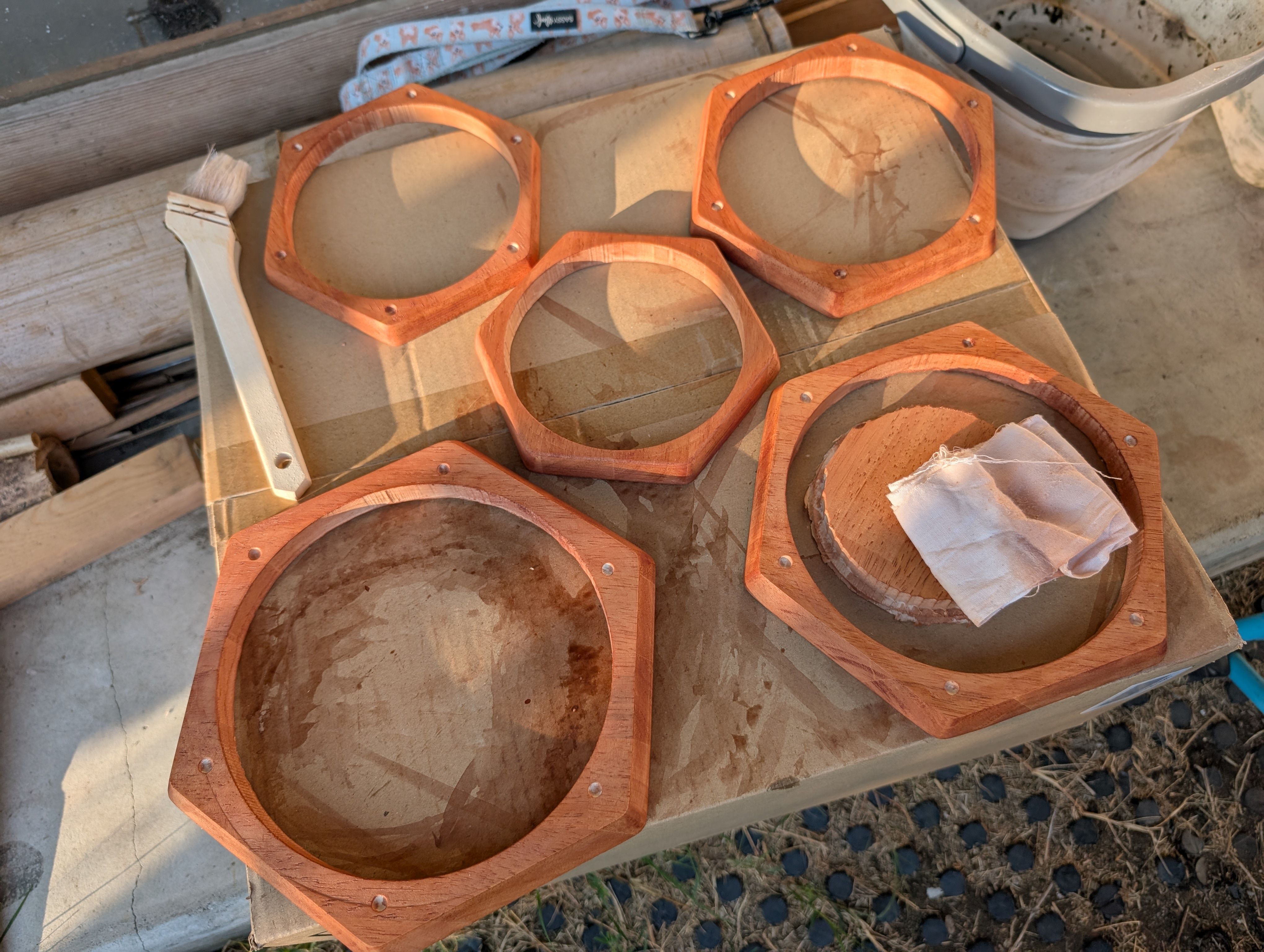
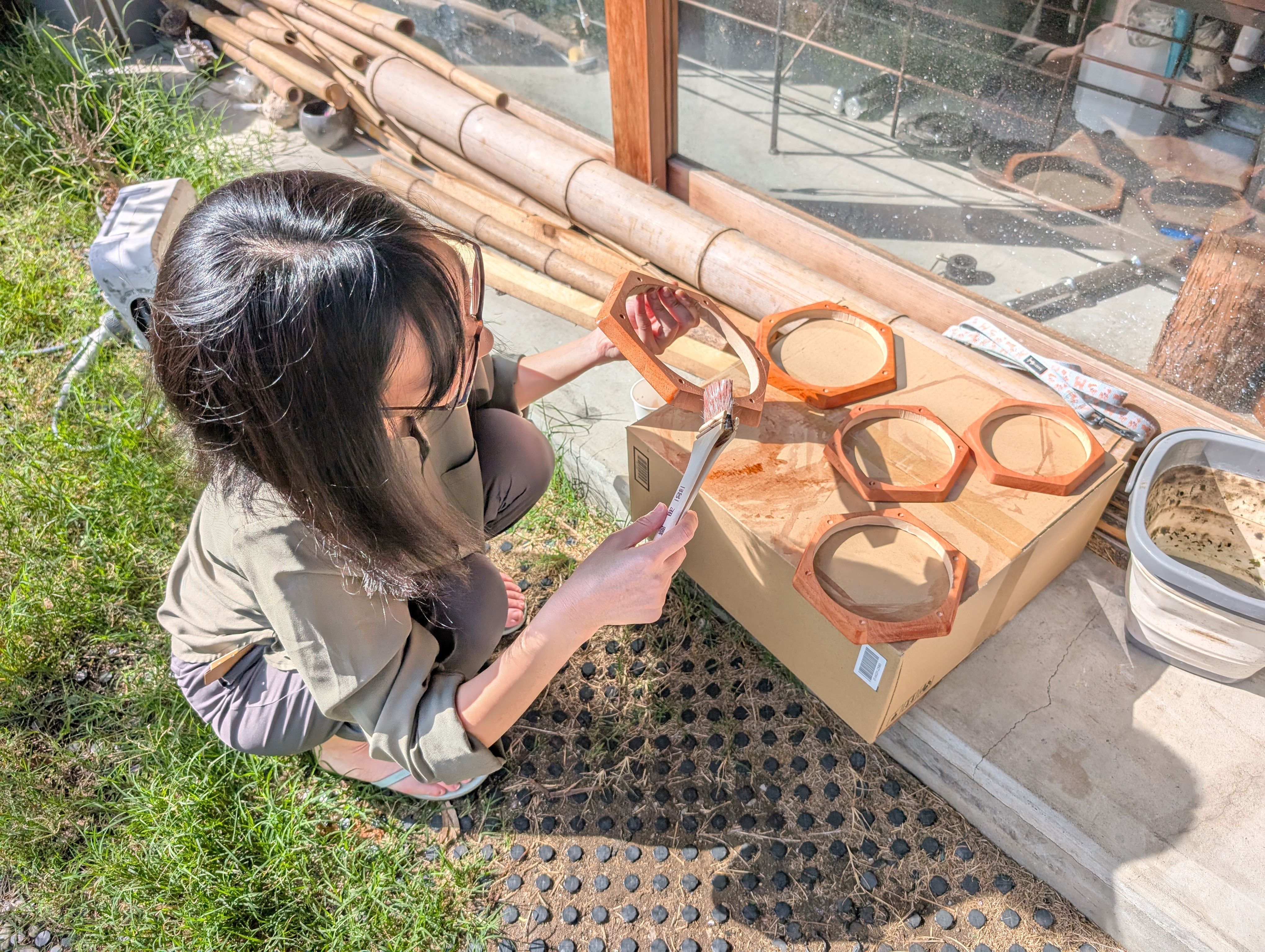
Progress after week 16
In week 18, I tried to finish it.
I sand them, and paint them with Persimmon tannin(Japanese traditional dye) and
beeswax.
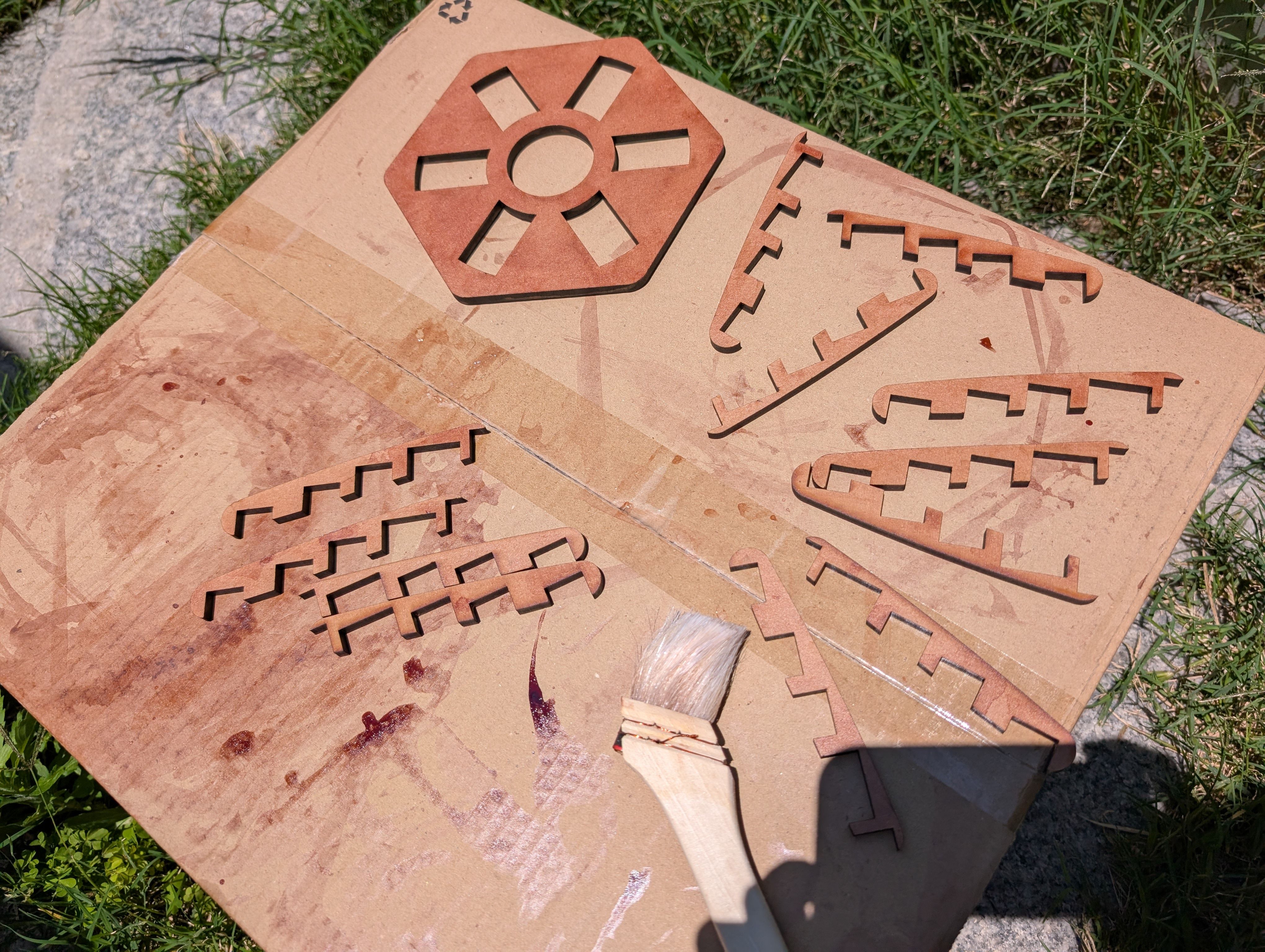
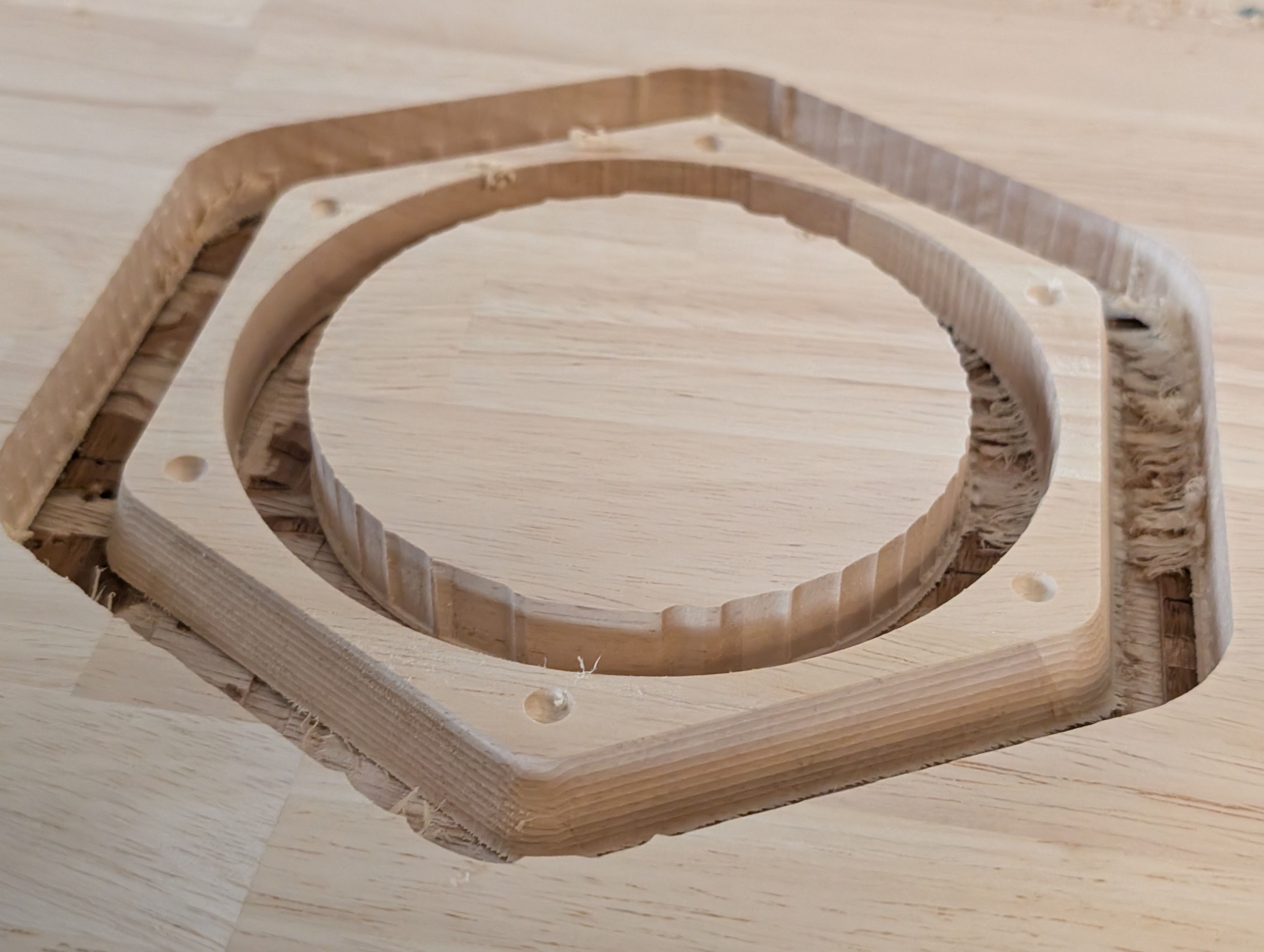
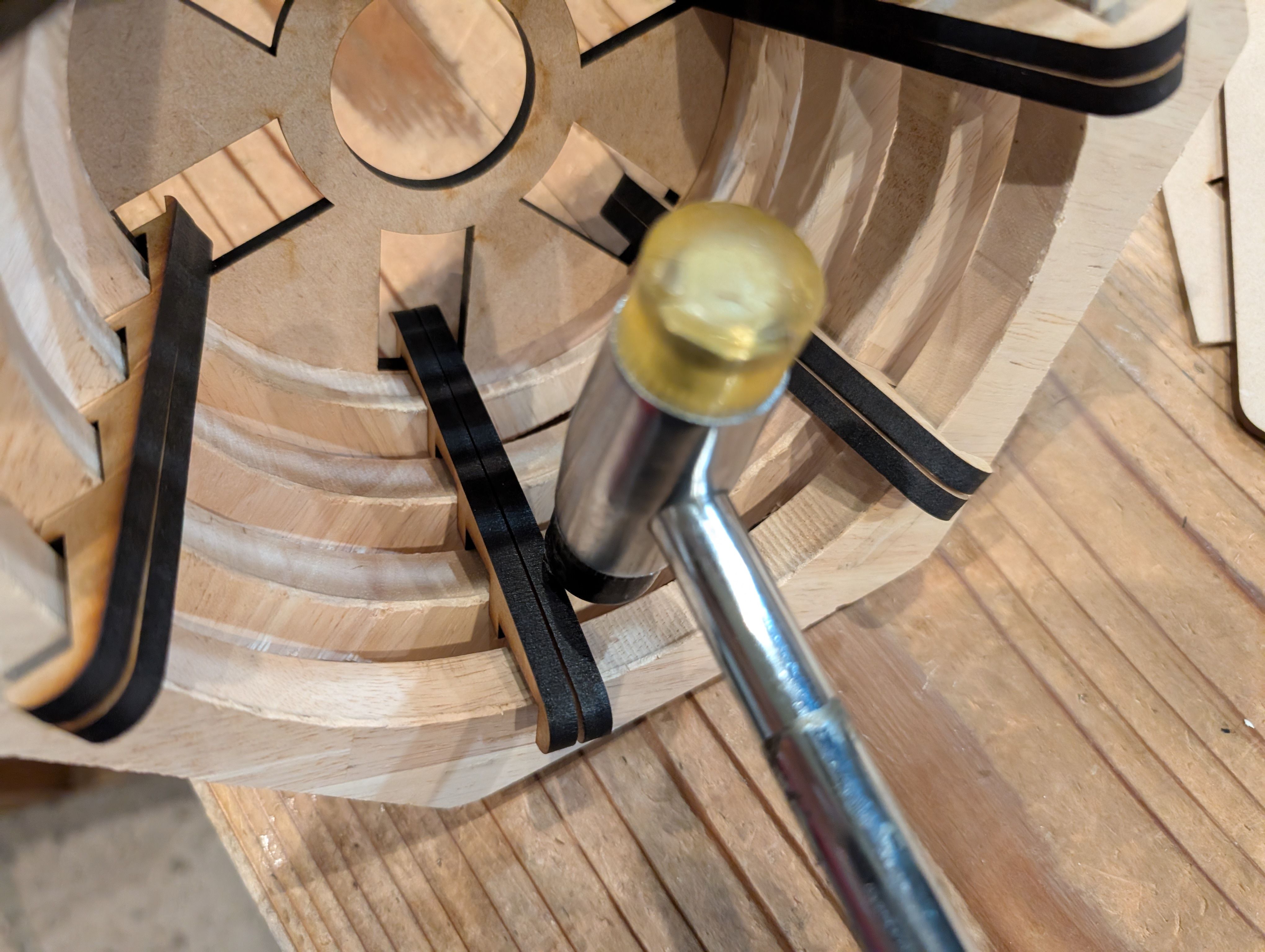
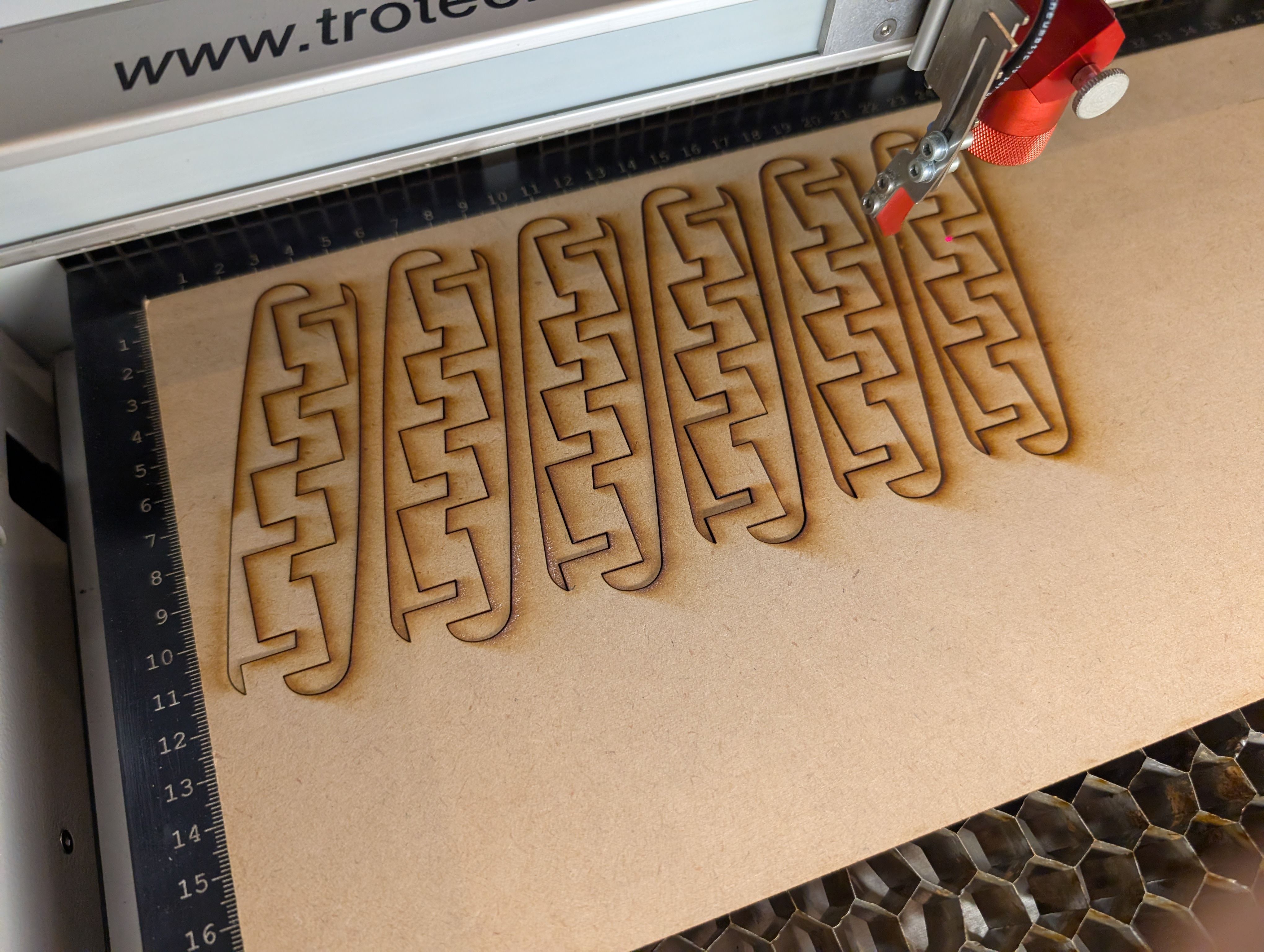
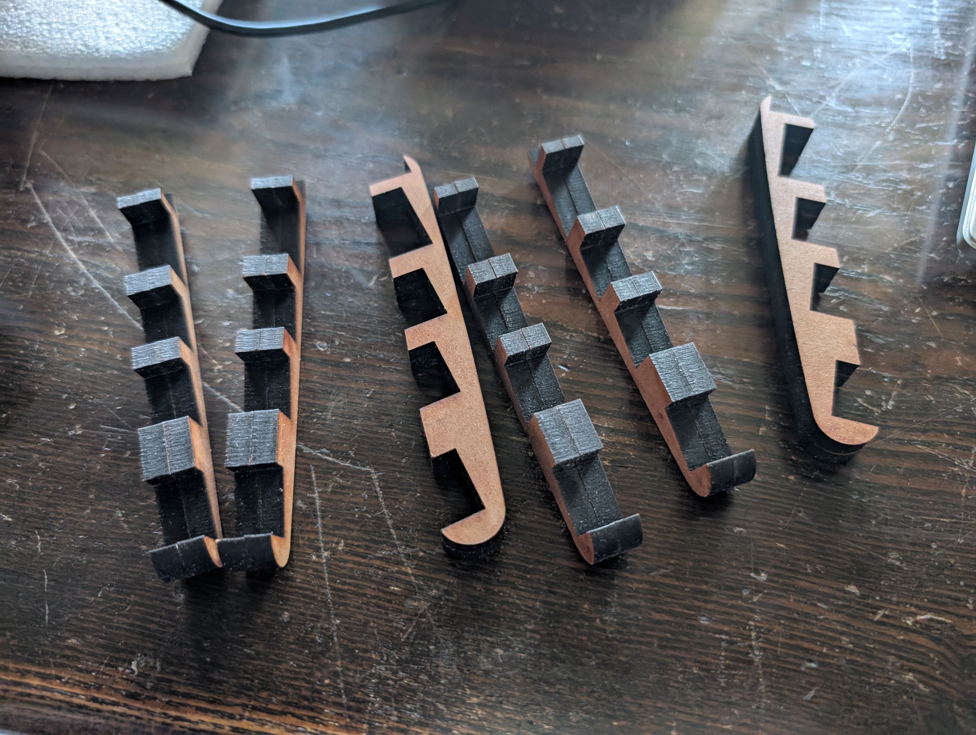
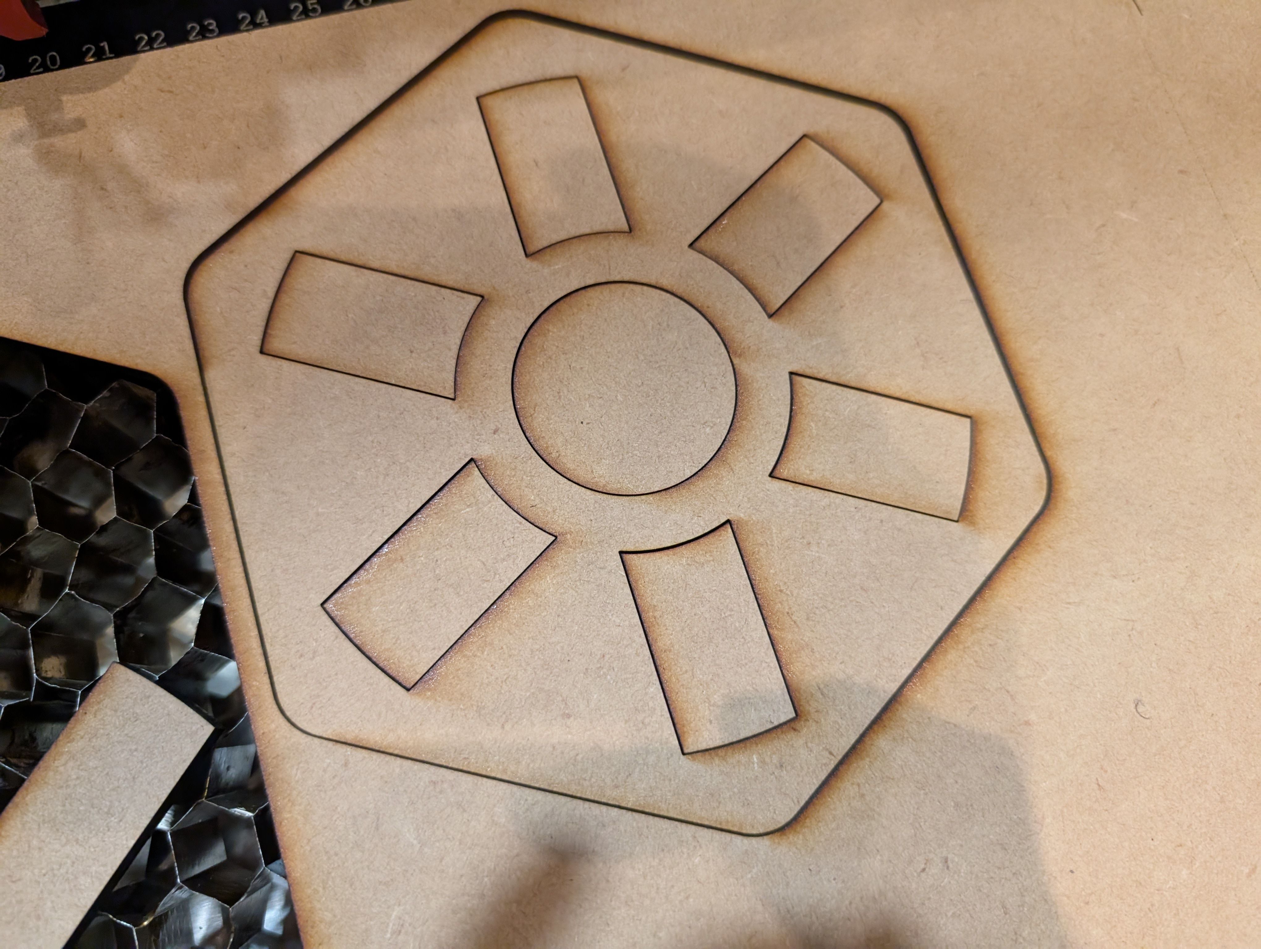
Base support Parts - Laser Cutting(Week 16)
As for the parts connecting woods milled, I tried to use CNC machining at first,
but it was too thin to cut out, so I decided to use laser cutting.
*Design of the connection part

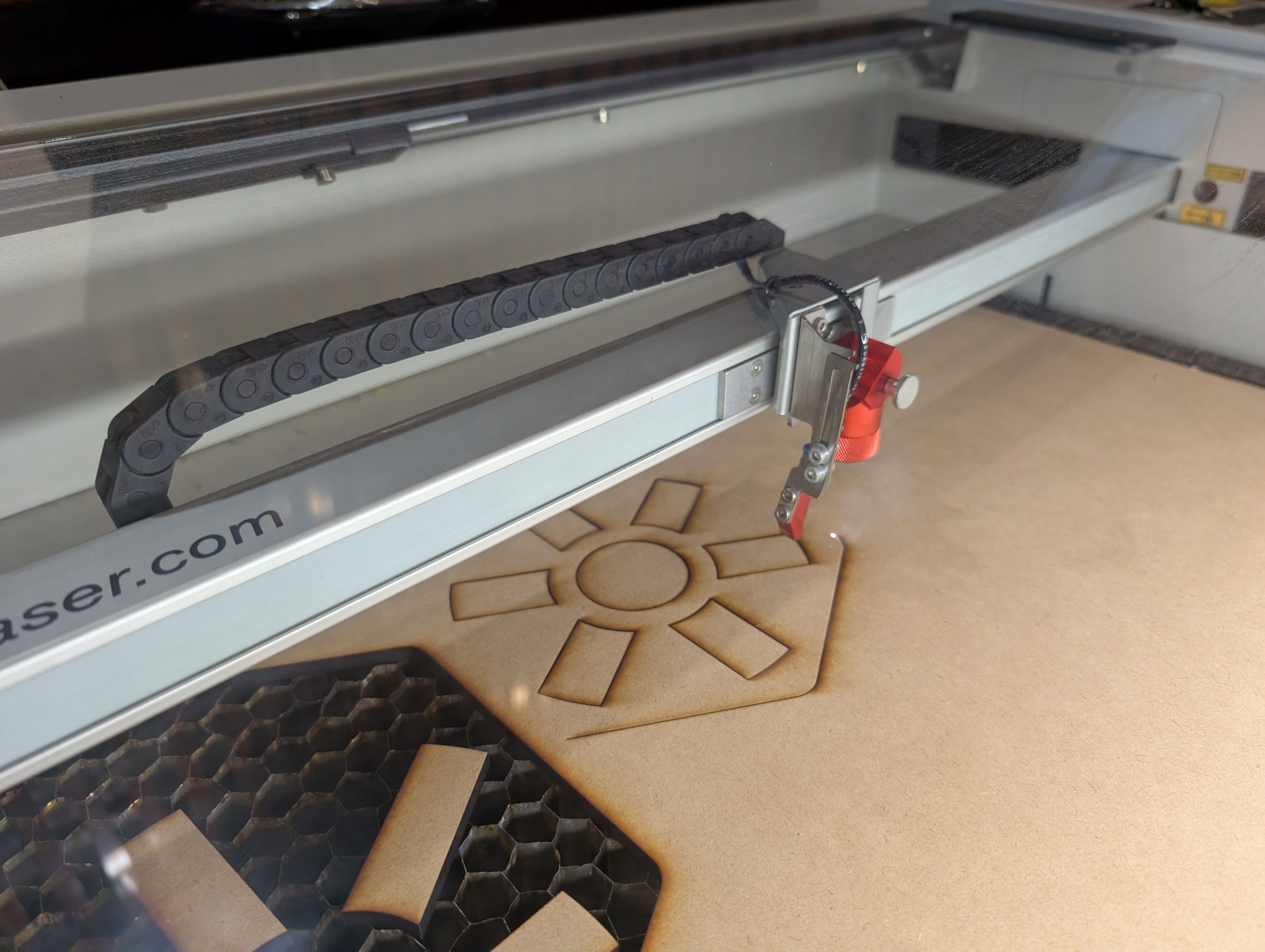
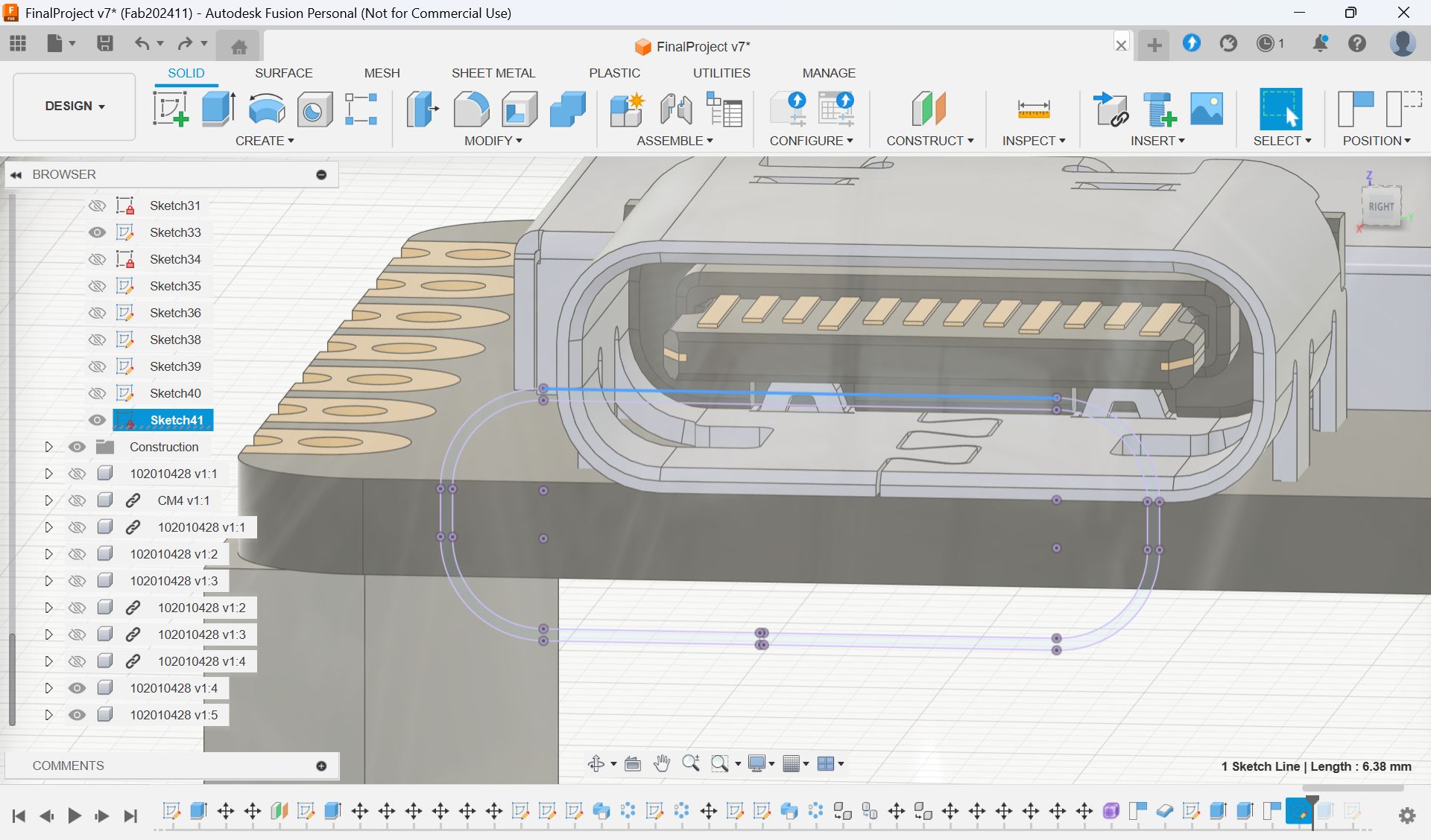
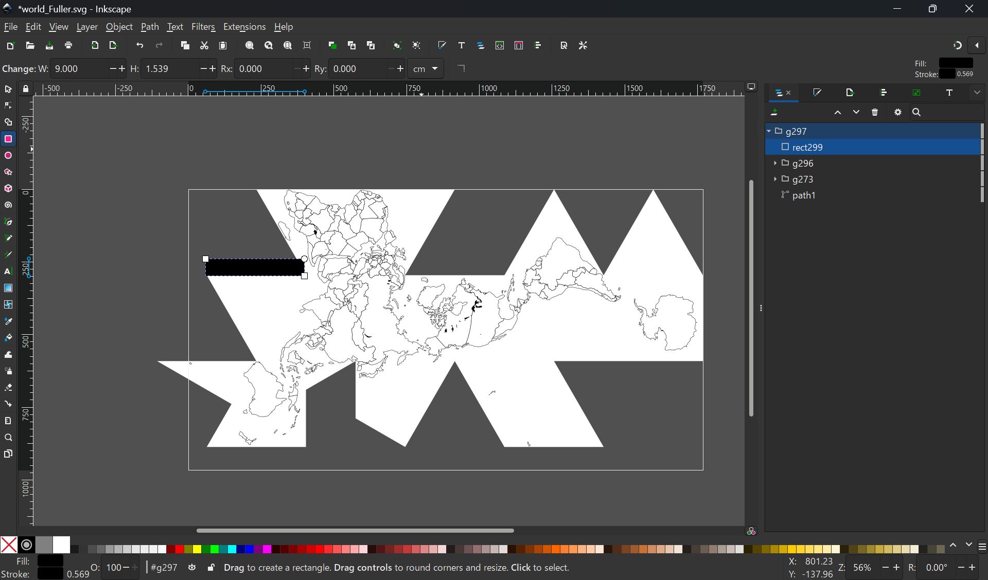
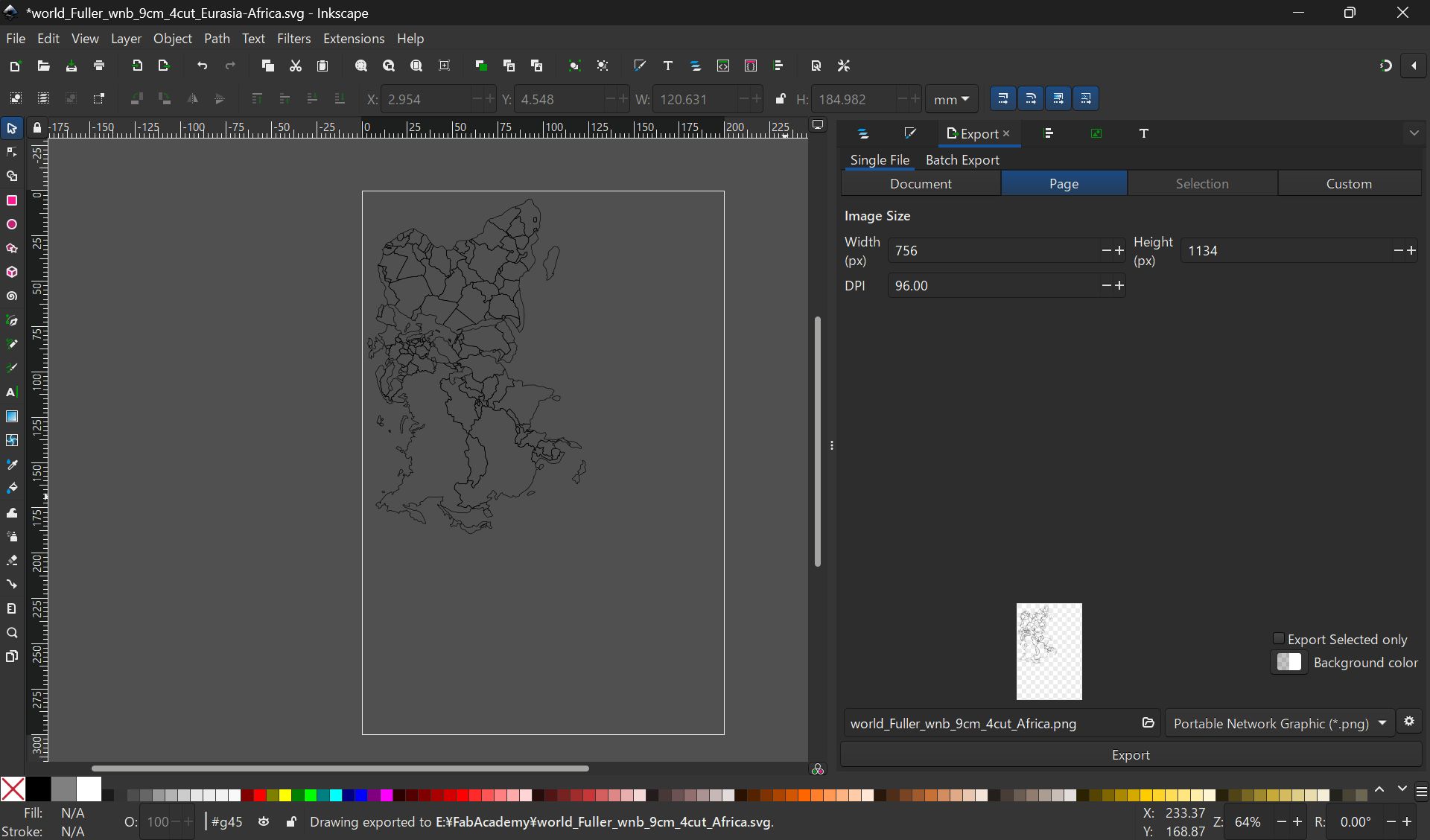
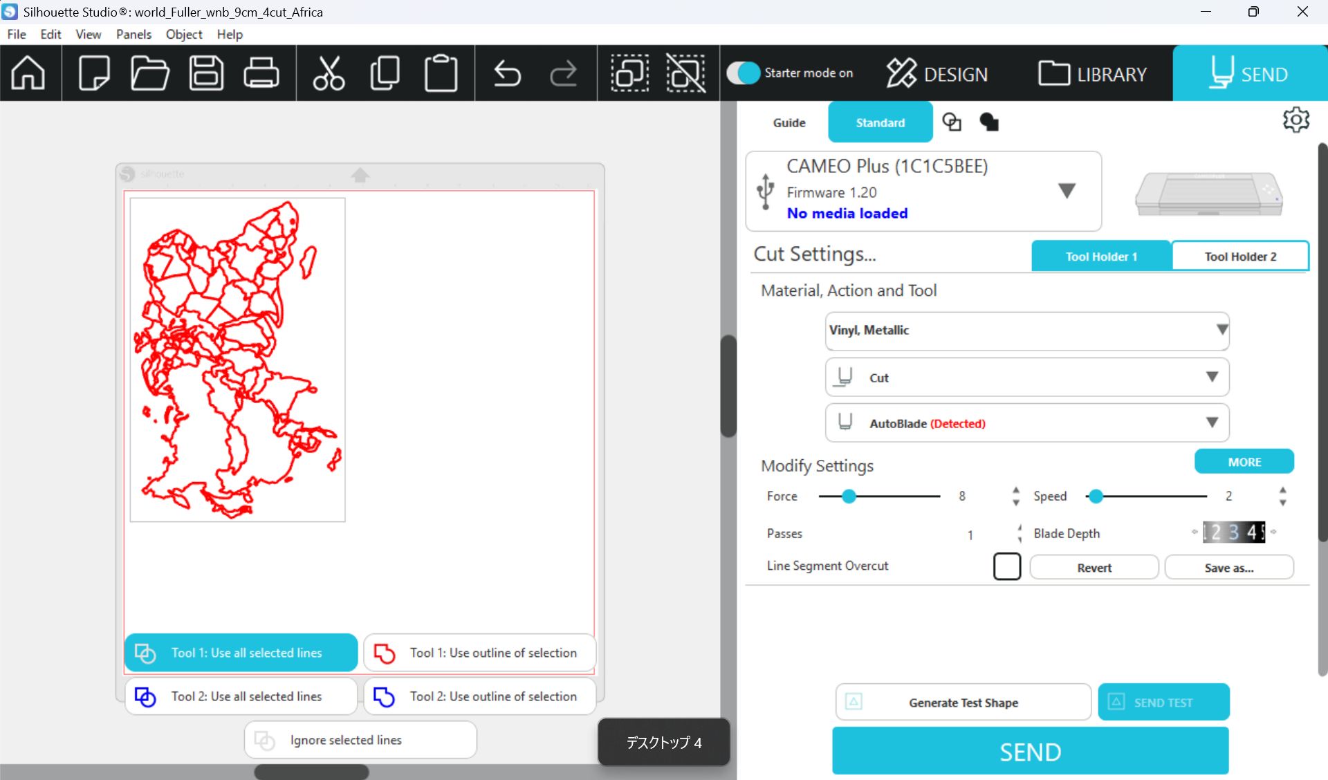
Map - Vinyl Cutting
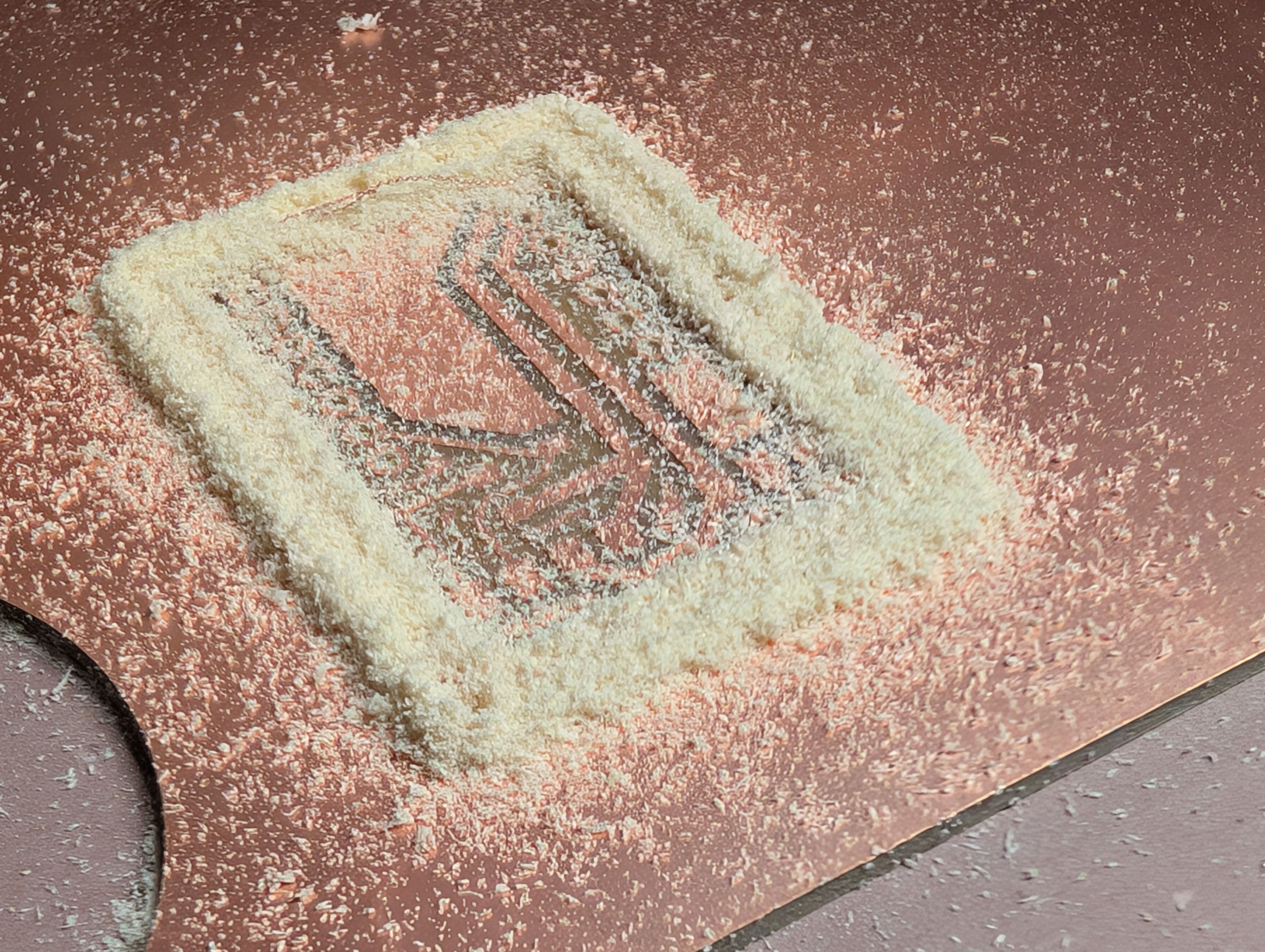
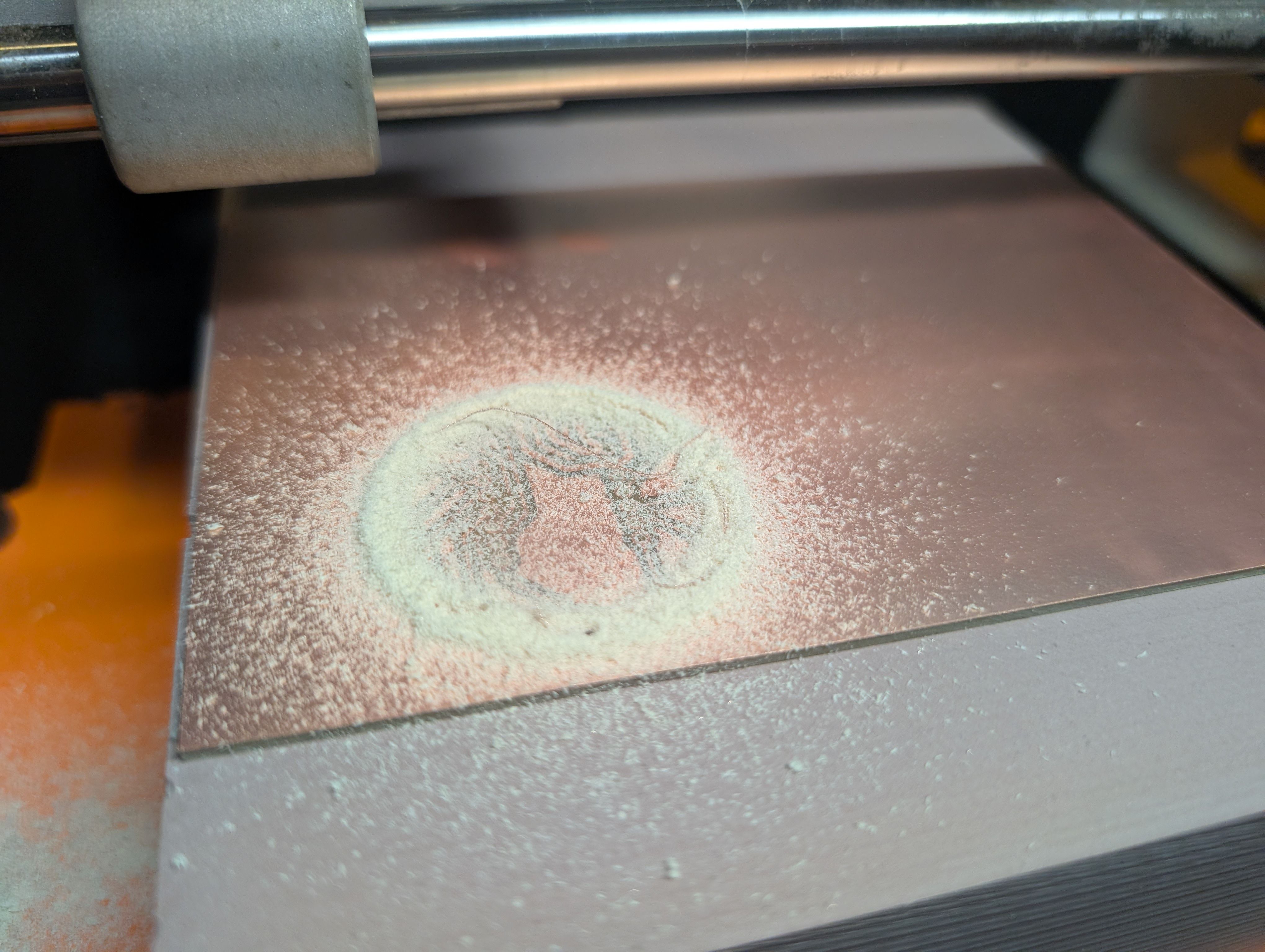
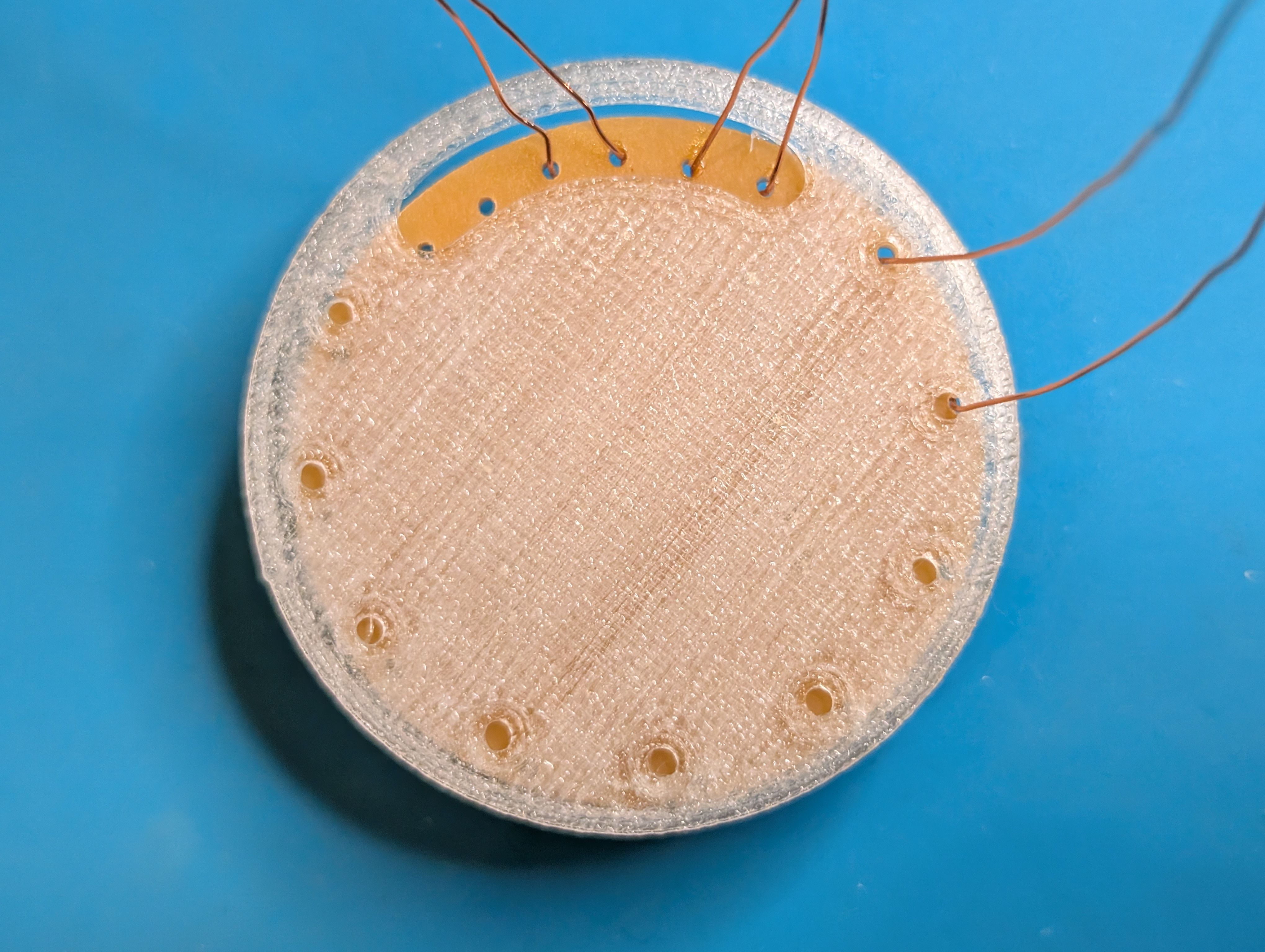
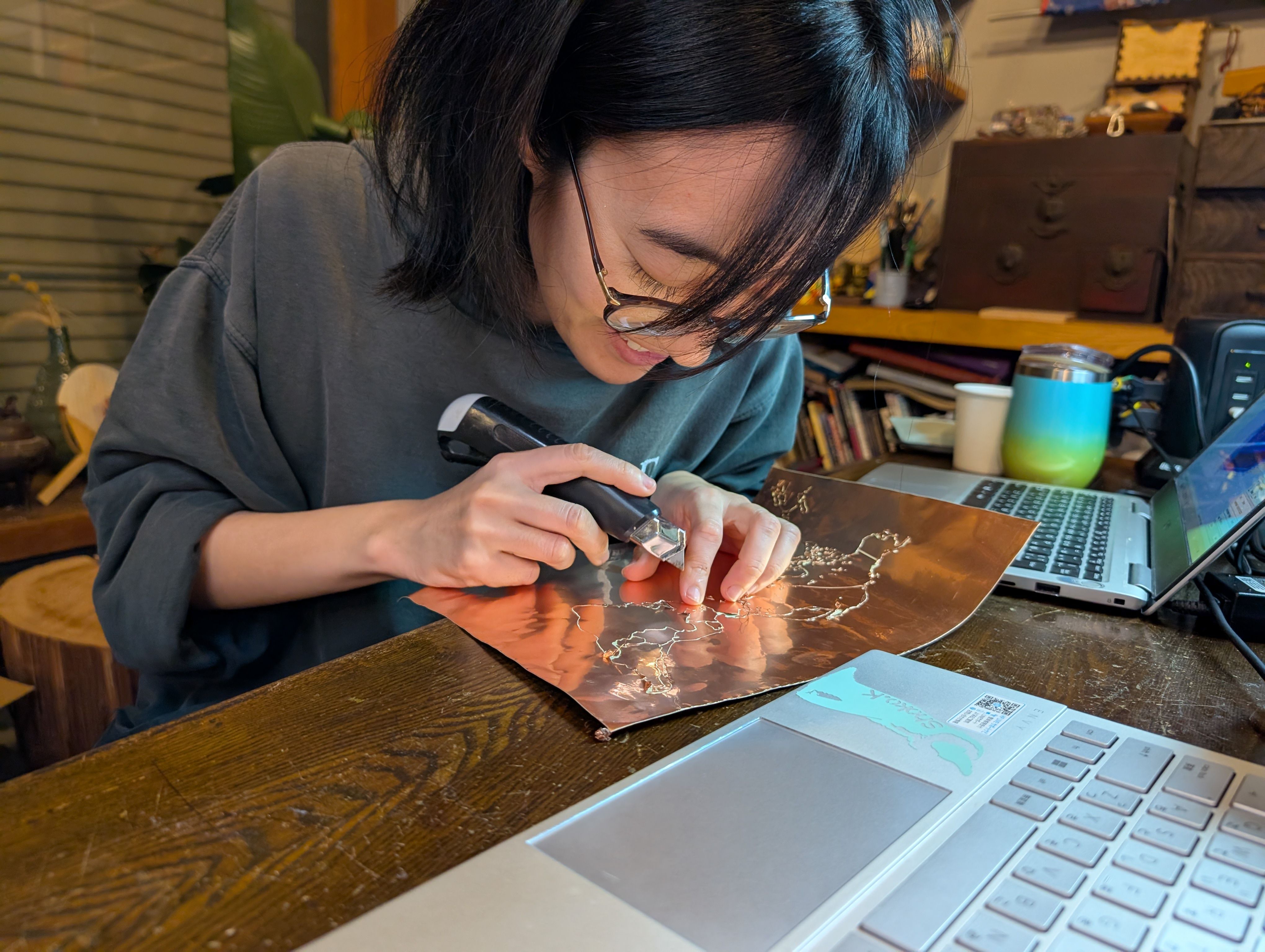
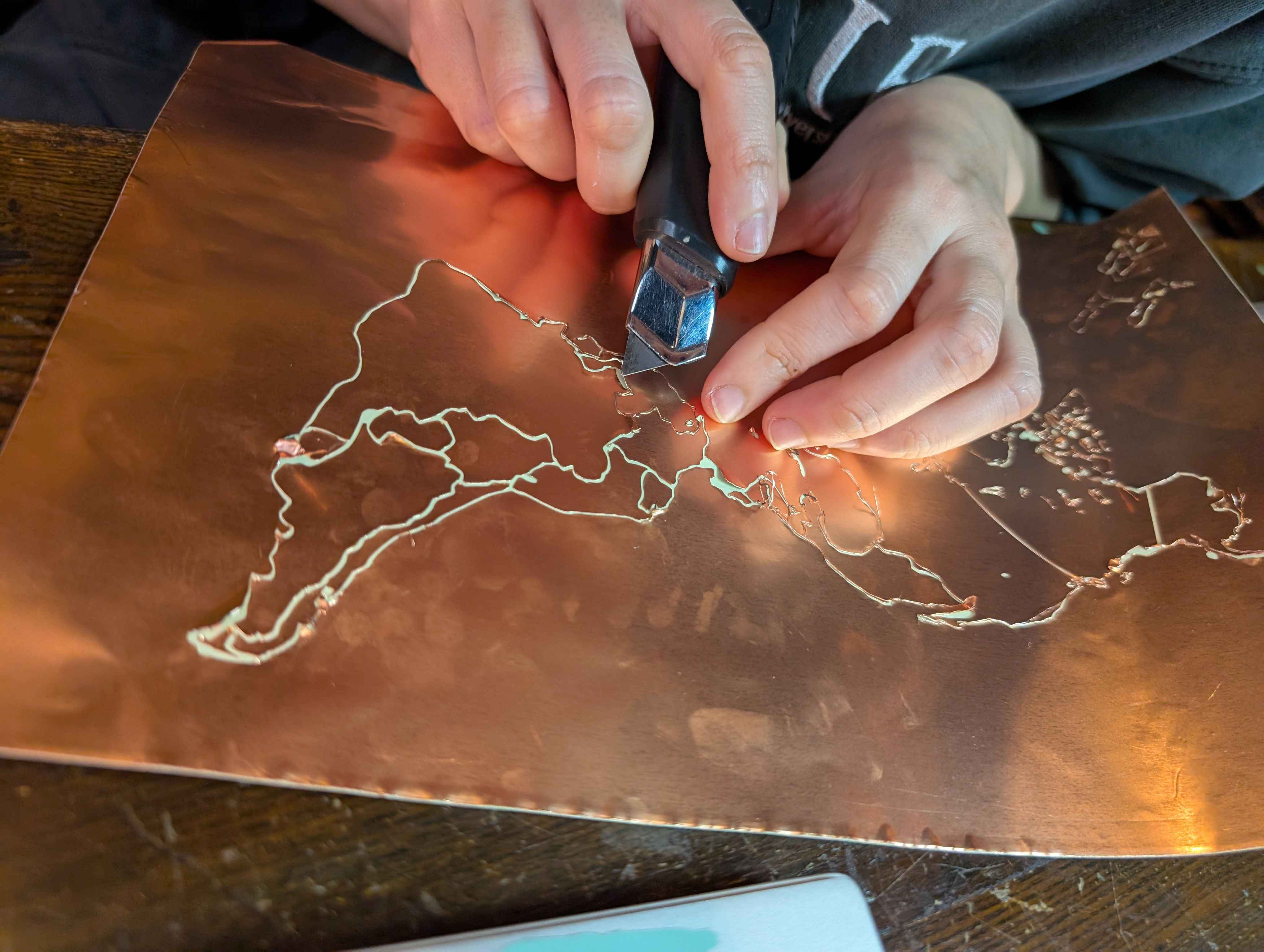
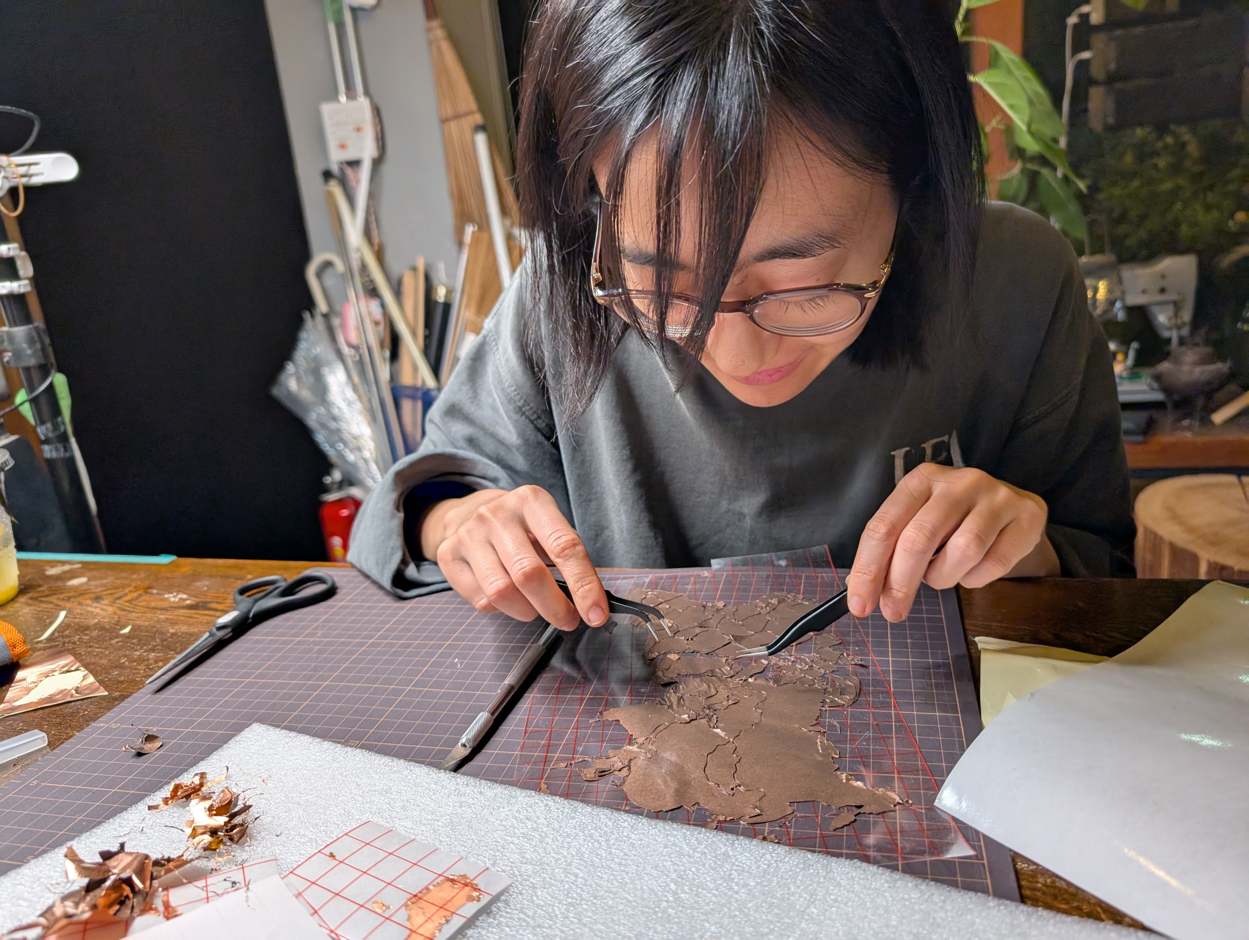
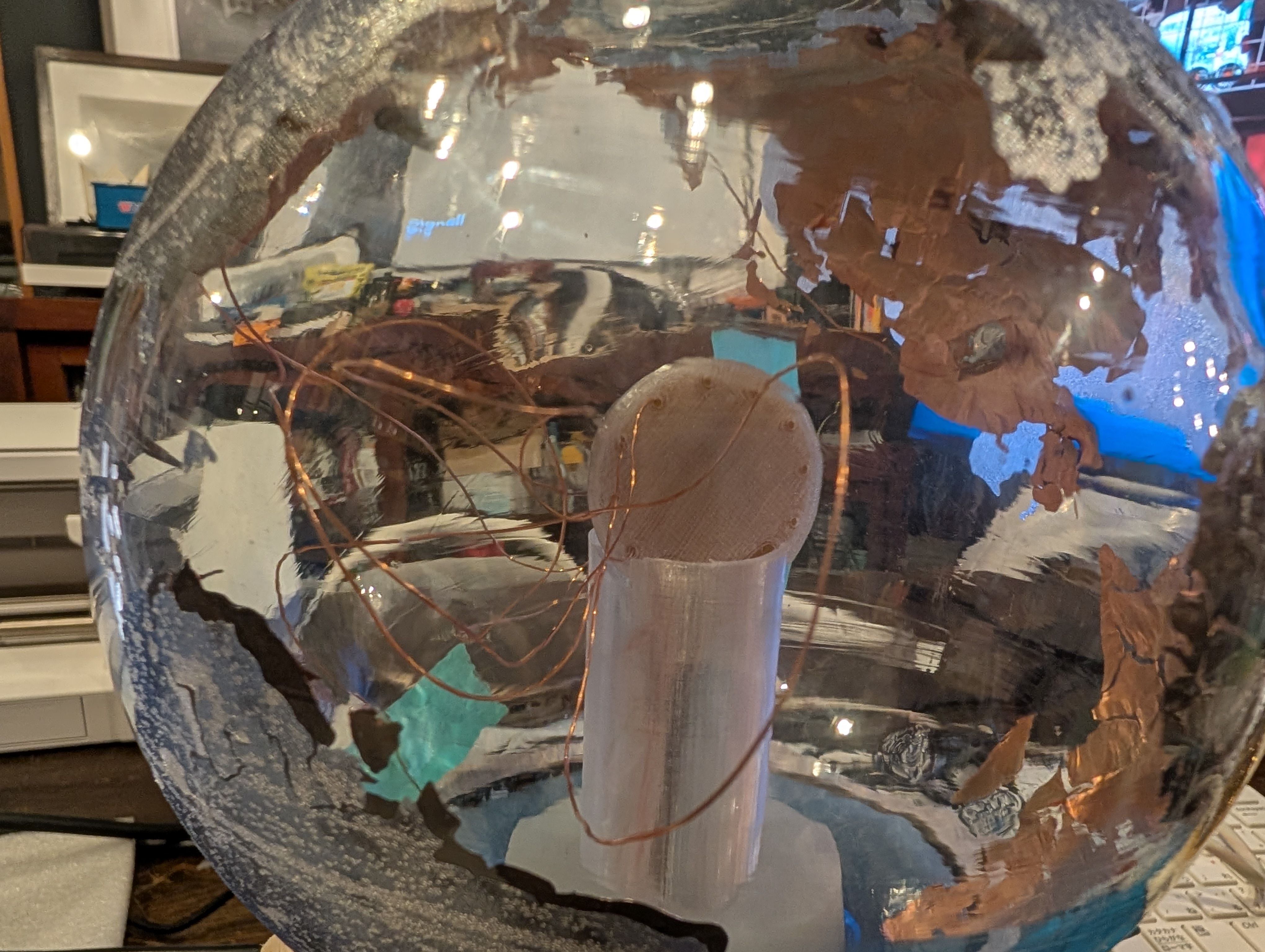
Copper Sheet Vinyl Cut
Copper sheet is cut into the shape of a country. Fixed to the inner surface of the
glass.
I wanted to map the globe while maintaining the relative positions of the countries,
so
I searched for a map projection that would suit this.
I used the map data from Wikipedia and adjusted in size with Inkscape:
File:Blank_world_map_Dymaxion_projection.svg
Export the map symmetrically with PNG (to be pasted from the inside of the sphere)
Used Silhouette Studio
Setting
Force: 8, Speed:2, Passes:1, Bade Depth: 5
*If the pressure or depth is too strong, the copper will float up, so it is
important
to use the right amount of Force and Depth.
Point
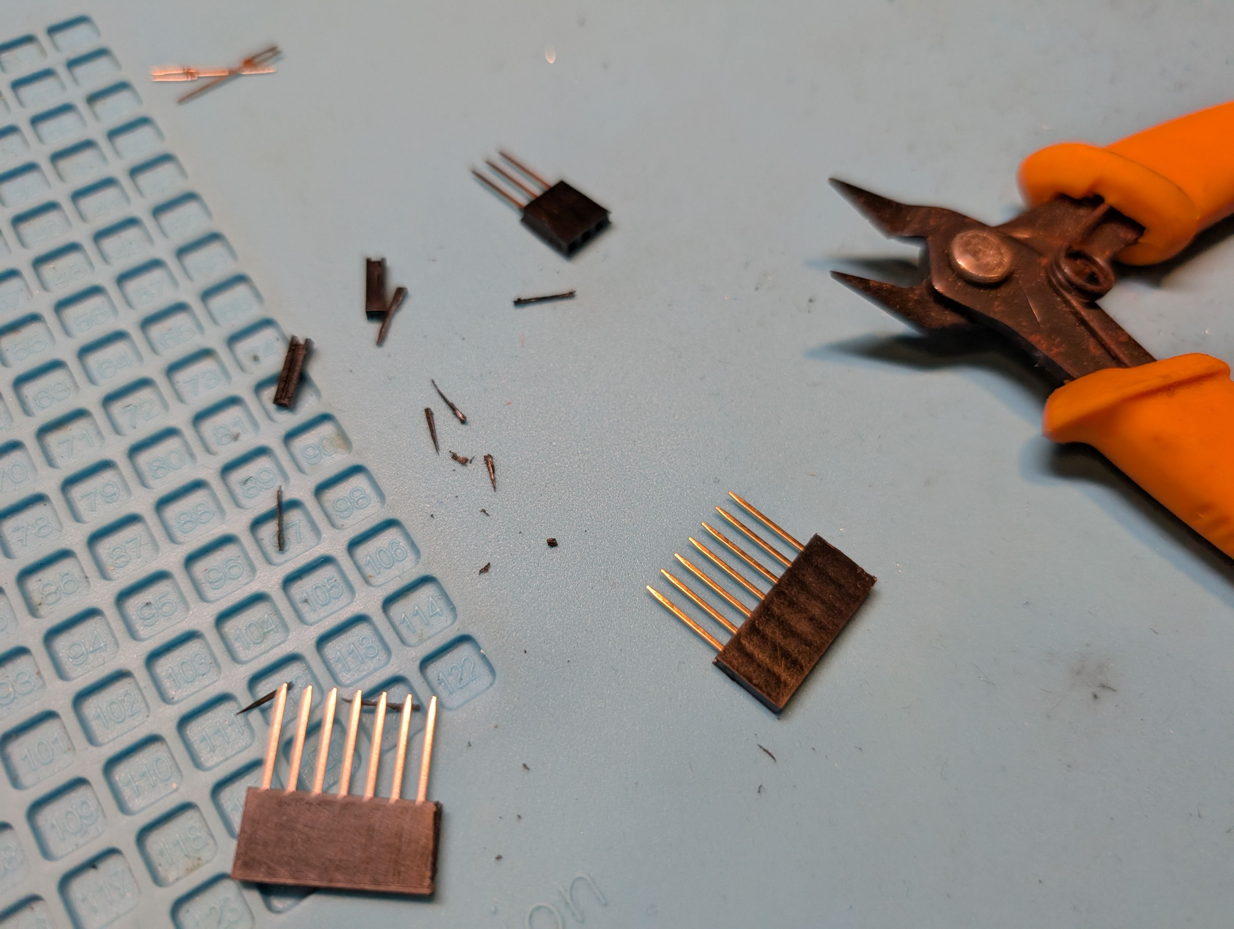
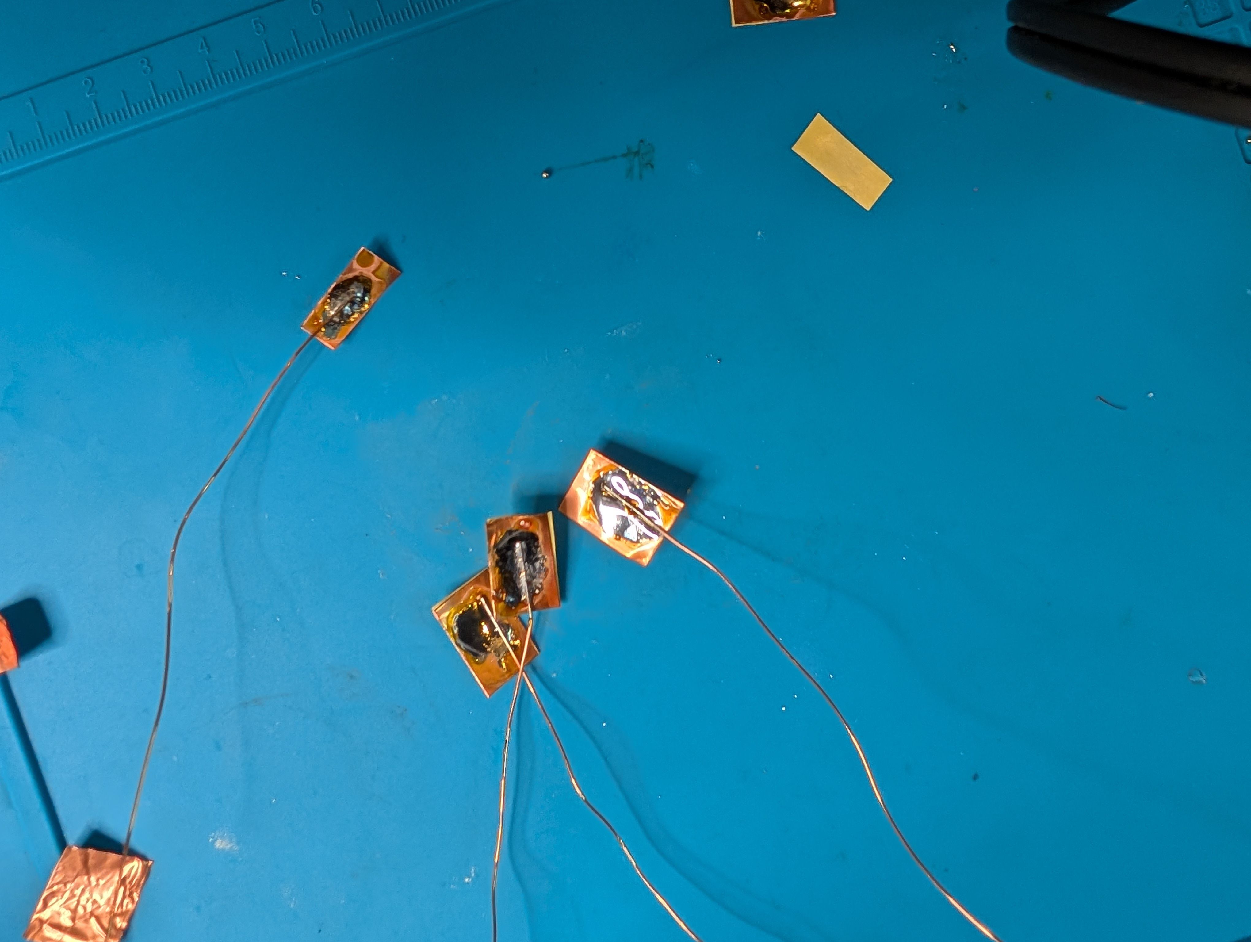
- How to fix the copper foil on the inner surface of the spherical glass. At first, I tried to fix the copper foil on the glass using an application sheet while maintaining the exact position of the countries, but it was difficult to fix the sheet on the glass, especially on the long horizontal Eurasian continent, and the sheet kept coming off. Since the fixation was weak, spray glue was used.
- Connection of copper wire from MCU6(soldering) Since it was difficult to solder inside the sphere, solder was fixed separately in the form of copper foil tape. It was successfully fixed in a country with a large area, but it was difficult to keep it fixed in a country too small.
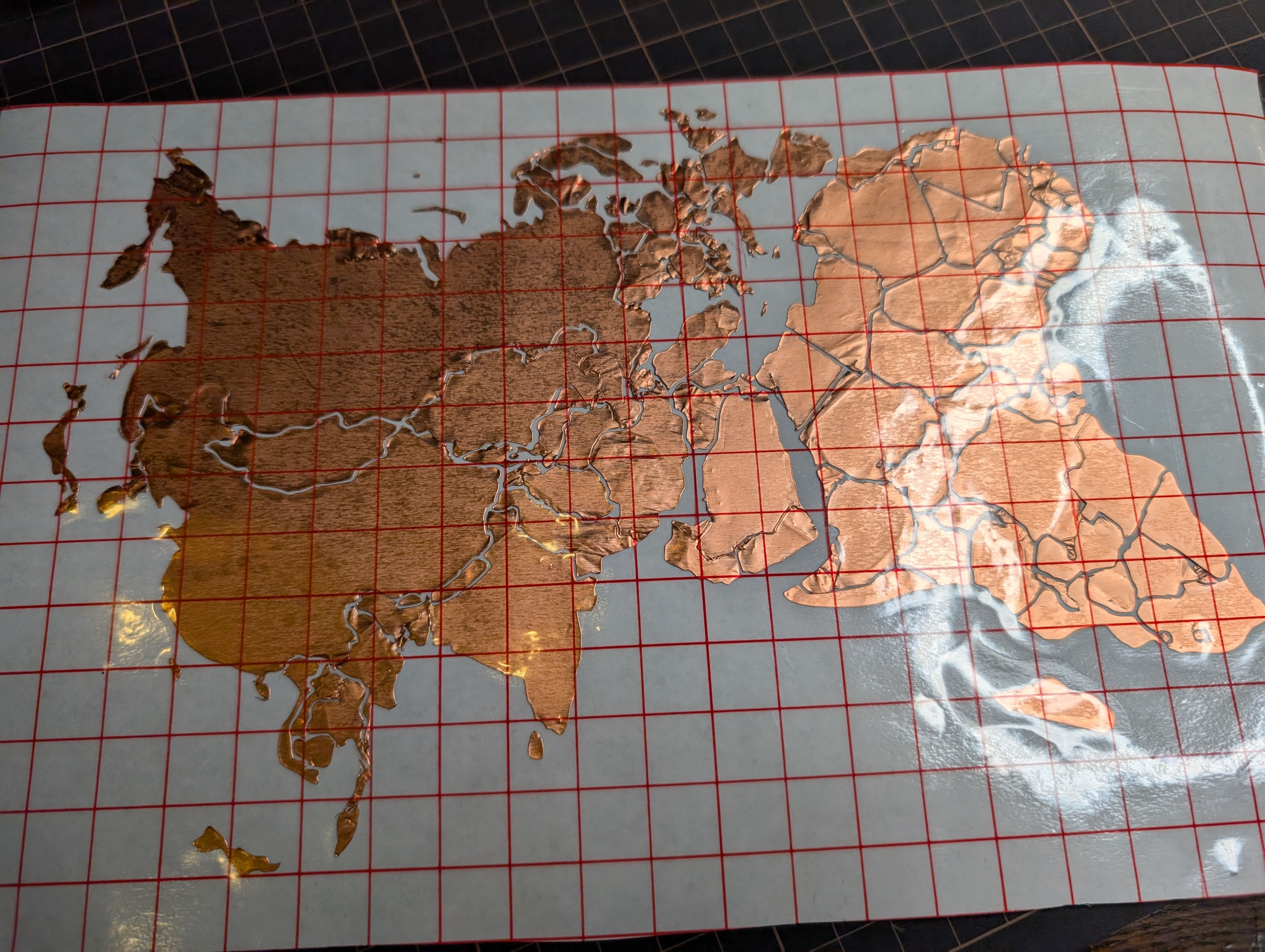
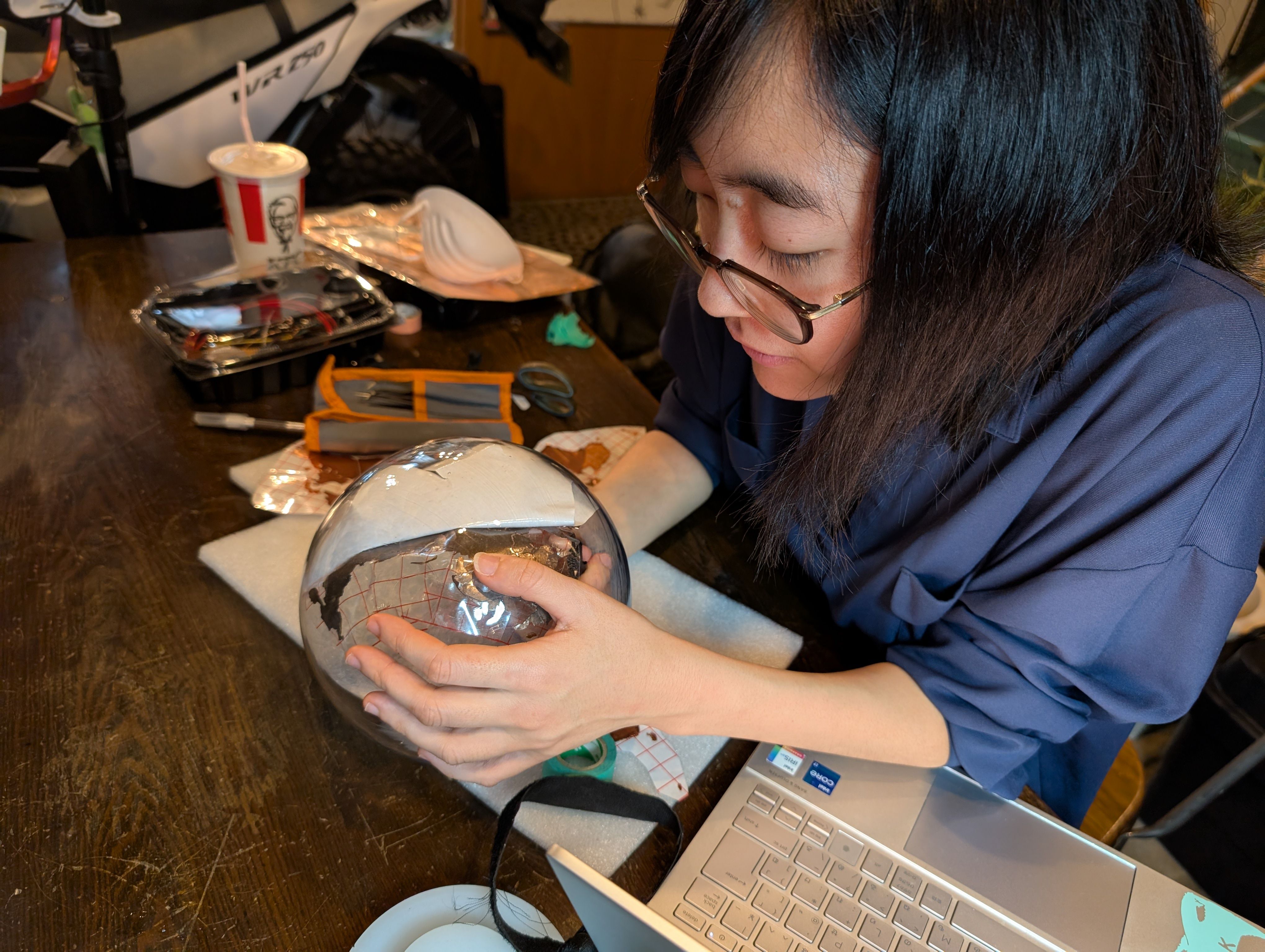
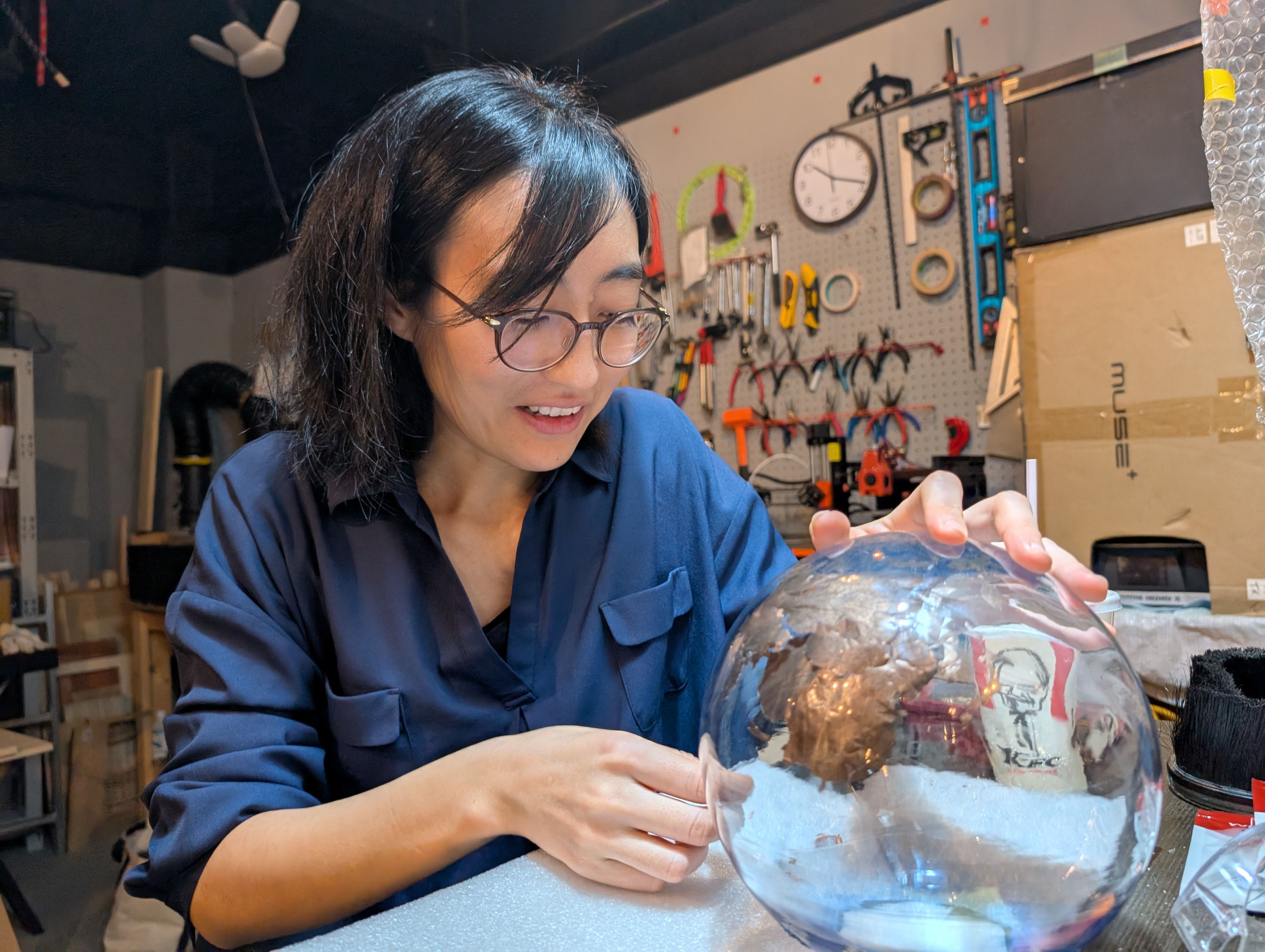
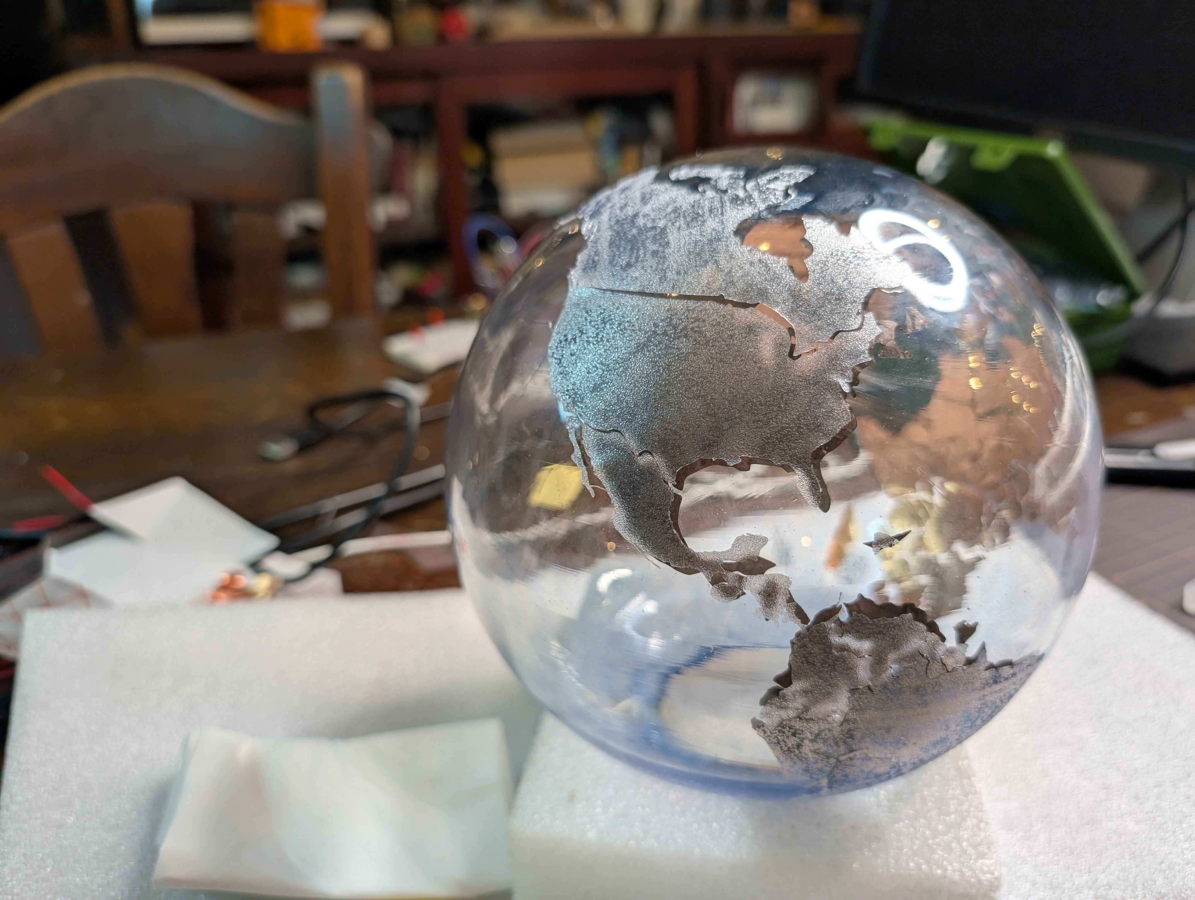
I also put a frosted glass-like sheet on the outside.
Programming
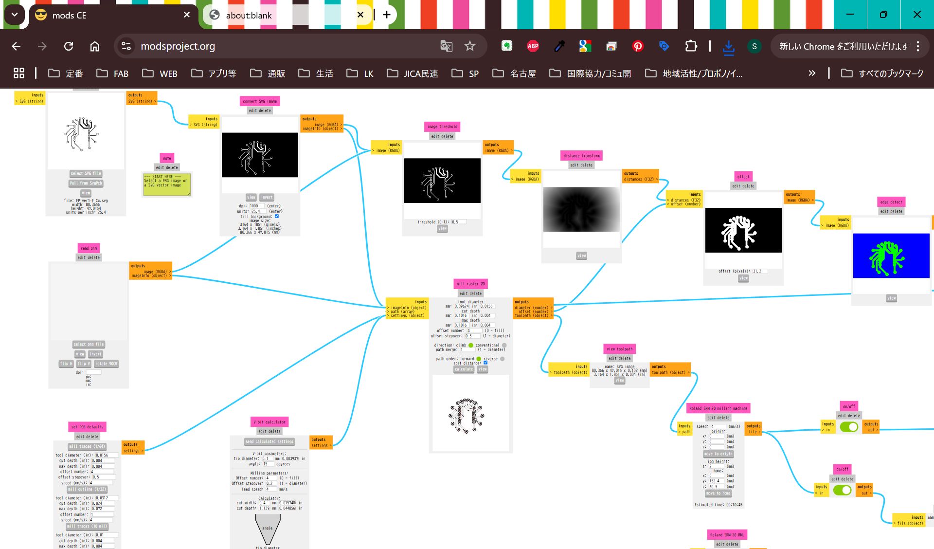
Processing for projection(Week 14)
In week 14, I tried processing for projection.
Try Video
https://processing.org/reference/libraries/video/Movie_play_.html
Add library
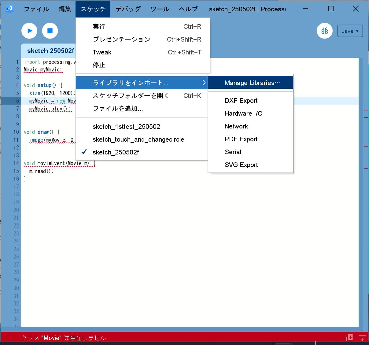
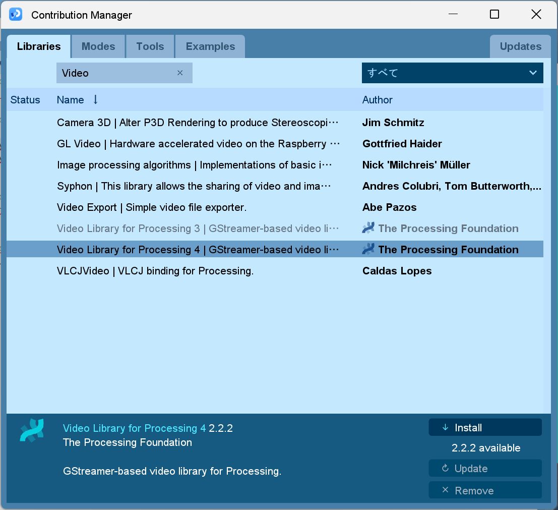
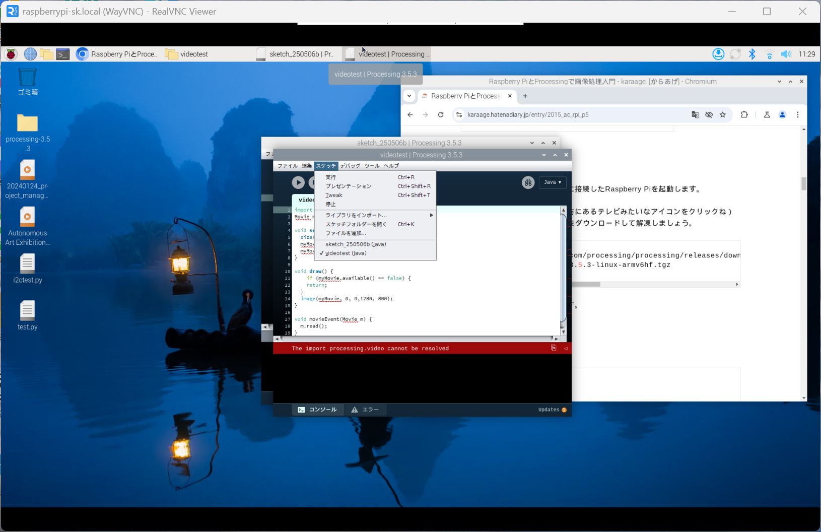
But, could not run the code…
Add library
Run the test code and it worked!
import processing.video.*;
Movie myMovie;

void setup() {
	size(1920, 1200);
	myMovie = new Movie(this, "tuktuk.mp4");
	myMovie.play();
}

void draw() {
	image(myMovie, 0, 0);
}

void movieEvent(Movie m) {
	m.read();
}
Try mask
recommended by Nagano-san
The error shows that the mask size should same size as the image/video
Make mask image
I got an error, so I asked ChatGPT. (for Chat GPT script, please see Week14 page)
Also, the image was cut off, so I adjusted the drawing part to be smaller.
import processing.video.*;
Movie myMovie;
PImage imgMask;

void setup() {
	size(1920, 1080);
	imgMask = loadImage("mask2.jpg");
	myMovie = new Movie(this, "tuktuk.mp4");
	myMovie.play();
}

void draw() {
	background(0);
	if (myMovie.available()) {
	myMovie.read();
	}
	PImage frame = myMovie.get();   // 現在のフレームをPImageに変換
	frame.mask(imgMask);            // マスクを適用
	image(frame, 0, 0,1280,720);   // 描画
}
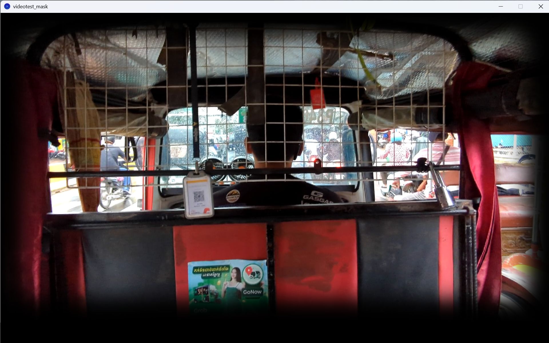
Nicely Masked!
Try Touch and play video!!
I asked Chat GPT. (for Chat GPT script, please see Week14 page)
Final code is as shown:
import processing.serial.*;
import processing.video.*;
Serial mySerial; //create local serial object from serial library
Movie myMovie;
PImage imgMask;
boolean playVideo = false;

//useful variables for serial communication
String myString = null; //variable to capture string data being transmitted over serial port
int nl = 10; //'nl' variable to represent a carriage return (end of line)...represented by '10' in this case
float myVal = 0.0; //'float' are non-whole numbers

PGraphics maskedFrame;

void setup(){
	size (1280, 720); //canvas size

	//initialize serial communication
	String portName = "COM5"; //put the com port number in square blaket
	mySerial = new Serial(this,portName,115200);//initialize and configure serial port...match baud rate with xiao
	myMovie = new Movie(this, "tuktuk.mp4");
	myMovie.pause();
	imgMask = loadImage("mask2.jpg");
	imgMask.resize(width, height);

	maskedFrame = createGraphics(width, height);

}

void draw(){
	while(mySerial.available() > 0) { //is there any information in serial monitor or empty
	myString = mySerial.readStringUntil(nl); //read string until carriage return received

	if (myString != null) {
		myString = trim(myString);

		if (myString.length() > 0) {
		try {
			myVal = float(myString);
			println(myVal);
		} catch (NumberFormatException e) {
			println(myString);
		}
		}
	}
	}

	background(0);

	if (myVal >= 80.0 && !playVideo) {
		println("Starting video...");
		playVideo = true;
		myMovie.play();
	}

	if (playVideo && myMovie.available()) {
	myMovie.read();
	//image(myMovie, 0, 0, width, height);
	//PImage frame = myMovie.get();
	//frame.resize(width, height);
	//frame.mask(imgMask);
	maskedFrame.beginDraw();
	maskedFrame.image(myMovie, 0, 0, width, height);  // Draw frame
	maskedFrame.blend(imgMask, 0, 0, width, height, 0, 0, width, height, MULTIPLY); // Apply mask
	maskedFrame.endDraw();

	image(maskedFrame, 0, 0);

	}

}
However, when I tried to increase the number of sensors to two, it crushed.
Again, I asked to Chat GPT.(for Chat GPT script, please see Week14 page)
I also modified Arduino code.
// ESP32 Touch Test
// Just test touch pin - Touch0 is T0 which is on GPIO 4.

void setup() {
	Serial.begin(115200);
	delay(1000);  // give me time to bring up serial monitor
	Serial.println("ESP32 Touch Test");
}

void loop() {
	int raw1 = touchRead(T1);
	int raw2 = touchRead(T2);

	int val1 = map (raw1,27000,32000,0,300);
	int val2 = map (raw2,25000,200000,0,300);

	Serial.print(val1);
	Serial.print(",");
	Serial.println(val2);
	delay(1000);
}
The above Arduino code and the following worked:
import processing.serial.*;
import processing.video.*;
Serial mySerial; //create local serial object from serial library
Movie[] movies = new Movie[2];
PImage imgMask;
PGraphics[] maskedFrames = new PGraphics[2];
int currentVideo = -1;
//boolean[] playVideo = { false, false };

//useful variables for serial communication
String myString = null;
int nl = 10;
//float myVal = 0.0;

void setup(){
	size (640, 360); //canvas size

	//initialize serial communication
	String portName = "COM5";
	mySerial = new Serial(this,portName,115200);
	movies[0] = new Movie(this, "tuktuk.mp4");
	movies[1] = new Movie(this, "perahera.mp4");
	for (int i = 0; i < movies.length; i++) {
	movies[i].pause();
	}
	imgMask = loadImage("mask2.jpg");
	imgMask.resize(width, height);

	for (int i = 0; i < maskedFrames.length; i++) {
	maskedFrames[i] = createGraphics(width, height);
	}
}

void draw(){
	while(mySerial.available() > 0) {
	myString = mySerial.readStringUntil(nl);

	if (myString != null) {
		myString = trim(myString);
		String[] parts = split(myString, ',');

		if (parts.length == 2) {
		try {
			vals[0] = int(parts[0]);
			vals[1] = int(parts[1]);
			println("val1: " + vals[0] + " val2: " + vals[1]);

			for (int i = 0; i < vals.length; i++) {
			if (vals[i] >= 80 && i != currentVideo) {
				switchVideo(i);
				break;
			}
			}

		} catch (Exception e) {
			println("Error:" + myString);
		}
		}
	}
	}

	background(0);
	//for (int i = 0; i < movies.length; i++) {
	//   if (vals[i] >= 80 && !playVideo[i]) {
	//   println("Starting video " + i);
	//   playVideo[i] = true;
	//   movies[i].play();
	//}
	//  if (vals[i] < 80 && playVideo[i]) {
	//   println("Stopping video " + i);
	// playVideo[i] = false;
	//movies[i].pause();
	//movies[i].jump(0);
	//}
	if (currentVideo != -1 && movies[currentVideo].width > 0) {
	maskedFrames[currentVideo].beginDraw();
	maskedFrames[currentVideo].image(movies[currentVideo], 0, 0, width, height);
	maskedFrames[currentVideo].blend(imgMask, 0, 0, width, height, 0, 0, width, height, MULTIPLY);
	maskedFrames[currentVideo].endDraw();

	image(maskedFrames[currentVideo], 0, 0);
	}
	}

void switchVideo(int newVideo) {
	if (currentVideo != -1) {
	movies[currentVideo].pause();
	movies[currentVideo].jump(0);
	}

	currentVideo = newVideo;
	println("Switching to video " + currentVideo);
	movies[currentVideo].play();
}

void movieEvent(Movie m) {
	m.read();
}
Processing with Raspberry Pi
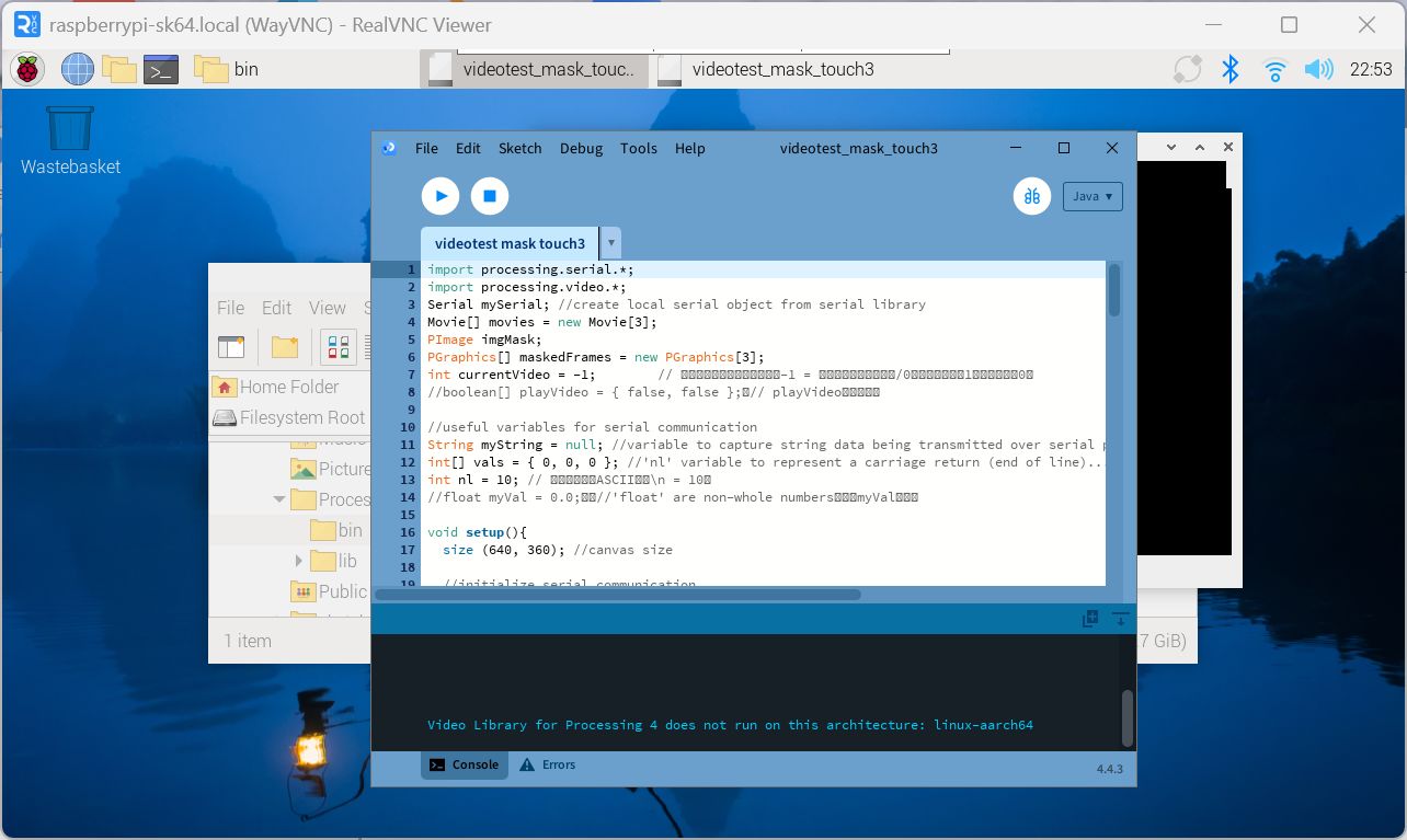
I tried to install it using the following site as a reference, but I got an
error.
https://snapcraft.io/install/processing/raspbian
There is no option to download it from the site.
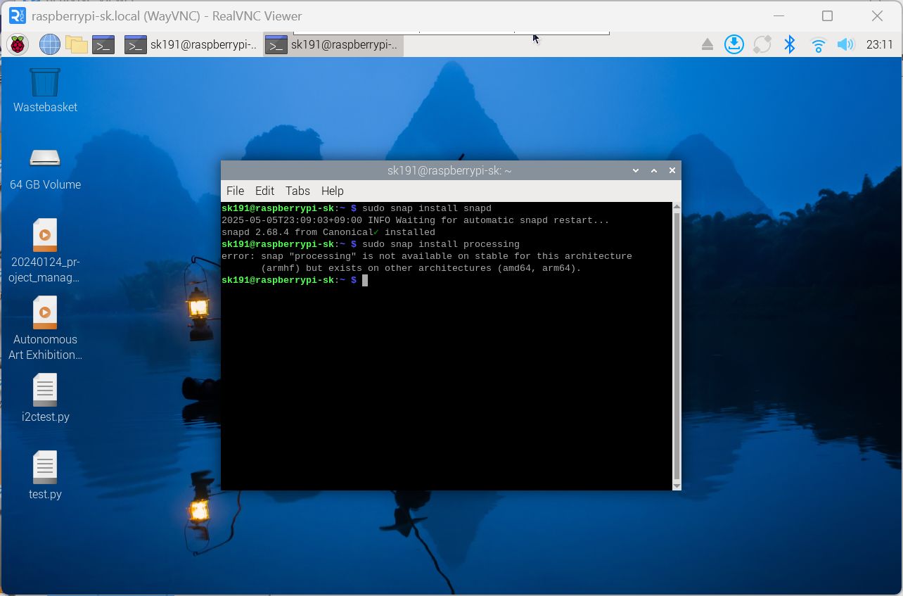
I first tried it with a Raspberry Pi 3, but the processing speed was slow, so I
switched to a
Raspberry Pi 5. Since the official method only supported 64-bit, I reinstalled the
64-bit
version of Raspberry Pi.
However, when I tried to install the Video library, it was not compatible with the
64-bit
version.
Finally, with Tsuchiya-san's support and by referring to the following page, I was
able to
install Processing 3 on the 32-bit version of Raspberry Pi 4 and somehow get the
video to play.
https://karaage.hatenadiary.jp/entry/2015_ac_rpi_p5
However, the processing speed is extremely slow, so I may reconsider combining
Raspberry Pi
with Processing.
For the details, please see Week14 Interface and Application Programming page.
Progress after week 14
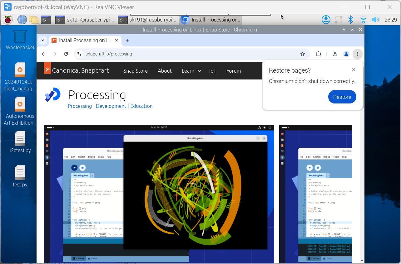
Following Tsuchiya-san's advice, I installed Processing (64bit) on my Raspberry Pi 5 (64bit) using the following steps, and was also able to install the video library.
- Download the pre-built Processing source from Processing's GitHub
GitHub Releases · processing/processing4
Download and unzip processing-4.4.3-linux-aarch64-portable.zip - Install GStreamer libraries, etc.
Execute the following commands in the terminal
sudo apt -y install cmake m4

											sudo apt -y install libssl-dev libcurl4-openssl-dev

											liblog4cplus-dev sudo apt -y install libgstreamer1.0-dev libgstreamer-plugins-base1.0-dev libgstreamer-plugins-bad1.0-dev

sudo apt -y install gstreamer1.0-plugins-bad gstreamer1.0-plugins-good gstreamer1.0-plugins-ugly gstreamer1.0-tools - When you unzip ”processing-4.4.3-linux-aarch64-portable.zip”, a folder called
”Processing” will be created. Go to that folder and double-click “Processing” in
the bin folder to launch it.
Alternatively, go to the relevant folder in the terminal and launch it with the command ./Processing. - Install the video library and run the test
The test was performed as follows.
- First retest with a single video version
- To simplify the code when supporting multiple video loads, I changed the code
from “loading as val and deciding whether to play on the Processing side” to
“receiving only the pin number”.
*Changed the Arduino side code also to send the pin number to Serial instead of val. - The video does not move smoothly, so I compressed the video as follows.
- Set the frame rate to 30↑ -r 30
- Set the bit rate to 0.5M
- Set the (Processing) frame rate to 30
- The command is as follows (test.mp4 and test_conv.mp4 are the video
names, and the changed video name)
ffmpeg -i test.mp4 -c:v libx264 -c:a aac -r 30 -b:v 0.5M -b:a 128k -vf
												"scale=1280:720" test_conv.mp4
I also received the following comment from Kae-san and made the corrections.
- When playing a video of a country, if the same country no is received, it will
try to play it from the beginning again = If you touch for a long time, it will
try to play from the beginning again.
→ Enter judgment of currentVideo != newVideo - To turn off the LED, enter code in Processing's draw to set CurrentState to “x” when the video playback ends
Furthermore, I wanted to turn on the NeoPixel light in conjunction with the video, it means, "When you touch, the video will play to the end and the screen will turn off. The LED will also turn off at the end of the video", so I made the following modifications:
- Detect the end of the video playback with Processing and make the image black
- Detect the end of the video playback with Arduino and turn off the LED
The final code is as follows.
import processing.serial.*;
import processing.video.*;
Serial mySerial; //create local serial object from serial library
Movie[] movies = new Movie[7];
PImage imgMask;
PGraphics[] maskedFrames = new PGraphics[7];
int currentVideo = -1; //same as null
//boolean[] playVideo = { false, false };
//useful variables for serial communication
String myString = null; //variable to capture string data being transmitted over serial port
//int[] vals = { 0, 0, 0 }; //'nl' variable to represent a carriage return (end of line)...represented by '10' in this case valsは整数の配列
int val = 0;
int nl = 10;
//float myVal = 0.0; //'float' are non-whole numbers
int videoStartTime = 0; // millis() で記録
float videoDuration = 0; // 秒 → millis に変換して使う
boolean videoEnded = false; // finish flag
void setup(){
size (1280, 720); //canvas size
frameRate(30);
println(Serial.list());
//initialize serial communication
//String portName = "COM5"; //for Windows PC
String portName = "/dev/ttyACM0"; //put the com port number in square blaket
mySerial = new Serial(this, portName,115200);//initialize and configure serial port...match baud rate with xiao
movies[0] = new Movie(this, "ag.mp4");
movies[1] = new Movie(this, "perahera_conv.mp4");
movies[2] = new Movie(this, "tuktuk_conv.mp4");
movies[3] = new Movie(this, "india.mp4");
movies[4] = new Movie(this, "praha.mp4");
movies[5] = new Movie(this, "us.mp4");
movies[6] = new Movie(this, "sa.mp4");
for (int i = 0; i < movies.length; i++) {
movies[i].pause();
}
imgMask = loadImage("mask2.jpg");
imgMask.resize(width, height);
for (int i = 0; i < maskedFrames.length; i++) {
maskedFrames[i] = createGraphics(width, height);
}
}
void draw(){
while(mySerial.available() > 0) { //is there any information in serial monitor or empty
myString = mySerial.readStringUntil(nl); //read string until carriage return(nl) received
if (myString != null) { //if serial is not empty
myString = trim(myString); //print serial
val = int(myString);
println(val);
if(val == 1) {
switchVideo(0);
} else if (val == 2) {
switchVideo(1);
} else if (val == 3) {
switchVideo(2);
} else if (val == 4) {
switchVideo(3);
} else if (val == 7) {
switchVideo(4);
} else if (val == 8) {
switchVideo(5);
} else if (val == 9) {
switchVideo(6);
}
}
}
background(0);
// If a video is currently playing, draw a frame of that video.
if (currentVideo != -1 && movies[currentVideo].width > 0) {
if (!videoEnded && millis() - videoStartTime > videoDuration) {
println("Video " + currentVideo + " ended.");
movies[currentVideo].pause();
movies[currentVideo].jump(0);
currentVideo = -1;
videoEnded = true;
mySerial.write("x\n");
println("Sending x to serial");
}
// Draw with mask while playing
if (!videoEnded) {
maskedFrames[currentVideo].beginDraw();
maskedFrames[currentVideo].image(movies[currentVideo], 0, 0, width, height);
maskedFrames[currentVideo].blend(imgMask, 0, 0, width, height, 0, 0, width, height, MULTIPLY);
maskedFrames[currentVideo].endDraw();
image(maskedFrames[currentVideo], 0, 0);
}
}
}
// --- Video switching function ---
// Argument newVideo: The number of the video to play (0 or 1)
void switchVideo(int newVideo) {
// If another video is already playing, stop it and go back to the beginning
if (currentVideo != -1 &¤tVideo != newVideo) {
movies[currentVideo].pause();
movies[currentVideo].jump(0); // set 0
}
// Begin playing the newly selected video
currentVideo = newVideo; // put newVideo =
println("Switching to video " + currentVideo);
movies[currentVideo].play();
// Record the video playback timing
videoStartTime = millis();
videoDuration = movies[currentVideo].duration() * 1000; // 秒→ミリ秒
videoEnded = false;
}
// --- Function called when a video frame is updated ---
// * Due to Processing specifications, this function is called every time a new frame arrives while the video is playing.
void movieEvent(Movie m) {
m.read();
}
Arduino for I2C and serial
In week 14, I tested the function that LED lighting up when touched sensor.
I used the following site as reference.
https://github.com/PaulStoffregen/Wire/blob/master/examples/slave_receiver/slave_receiver.ino
Also, when I searched for "How to light up the LED of xiaoRP2040 with
xiaoESP32-c3 as
Master and xiaoRP2040 as Slave", I found the following similar document.
https://fabacademy.org/2024/labs/puebla/students/daniela-monterrubio/assignments/week13.html
For the test code, please see Week14 page.
Also, as recommended by Neil, I considered connecting the Touch sensor via Networking and tried SAMD touch and networking. However, finally, I decided to start from few countries as 1st spiral.
Modification
On the globe, it seems it also works, but sometimes it doesn't work well.
In order to make it compatible with Processing code, the following modifications
were
made.
- Changed Arduino to send pin numbers to Processing, not val.
Prime:
- Improv slow touch detection: Remove delay(1000); in loop + made it a function.
Determine immediately after touch, and if touched, delay 1.5 seconds in
sendLocation function
(to avoid multiple detections during one touch). However, if there is no touch, it is better not to add a delay (because it will slow down the recognition the next time you touch). - Basically, adding a long delay means that the device will wait without
performing other processing, so it is not recommended.
This is fine for simple programs, but it can slow down the process of receiving data via serial communication, etc., for the time it takes to wait. - Include "detect when not touched": Send 0, etc. when there is no
touch.
(The Secondary side only accepts data that is different from the currentstate, so there is no reaction if you tap the same country twice in a row)
*In Processing, sending 0 would stop video, so we considered modifying it so that nothing would be sent when there is no touch, but we solved it by sending the string x instead of 0.
Secondary:
- The length of time the LED is displayed should be determined by the
specification, such as keeping the LED on until the video playback ends, or for
how many seconds, and the control should be included in the code.
For example, instead of turning on the LED when it is received, you can simply update the State, and then use if (currentState == '1') to keep it on depending on the State. You can turn off the LED by putting CurrentState = 'x'.
Furthermore, I wanted to turn on the NeoPixel light in conjunction with the video, it means, "When you touch, the video will play to the end and the screen will turn off. The LED will also turn off at the end of the video", so I made the following modifications:
- Detect the end of the video playback with Processing and make the image black
- Detect the end of the video playback with Arduino and turn off the LED
I was also recommended the following.
- Perform calibration
(to automatically adjust the touch sensitivity because the touch threshold changes depending on the location)
In the end, since it is difficult to adjust the touch sensitivity after placing it in
the glass globe, I decided to implement a calibration function.
Based on what
Kae-san taught me about the concept, I asked ChatGPT how to implement it.
Also,
after actually assembling it, XIAO will not be connected to the PC and there is a
possibility that the serial monitor will not be visible, so I turned on the LED
during calibration and when it was completed so that I could tell the timing.
The final code is as follows
Prime:
#include <Wire.h>

String serialBuffer = "";

#define NUM_TOUCH_PINS 3
int touchPins[NUM_TOUCH_PINS] = {T1, T3, T4};
int baseLine[NUM_TOUCH_PINS];
int touchLine[NUM_TOUCH_PINS];
int threshold[NUM_TOUCH_PINS];

void calibrateTouchPins();
void sendLocation(char location);
void sendLocationString(char cmd);
int averageTouchRead(int pin, int samples = 30, int delayMs = 10);

bool lastTouched[NUM_TOUCH_PINS] = {false};

void setup() {
  Wire.begin();
  Serial.begin(115200);
  delay(1000);  // give me time to bring up serial monitor
  calibrateTouchPins();  // calibration
  Serial.println("ESP32 Touch Calibrated!");
}

void loop() {

  while (Serial.available() > 0) {
    char inChar = (char)Serial.read();
    if (inChar == '\n') {
      serialBuffer.trim(); // 前後空白を除去

      if (serialBuffer == "x") {
        sendLocationString('x');
        serialBuffer = "";  // バッファクリア
        return;  // このループはここで終了(タッチ判定はスキップ)
      } else if (serialBuffer == "c") {
        sendLocationString('c');
        serialBuffer = "";  // バッファクリア
        return;  // このループはここで終了(タッチ判定はスキップ)
      }
      serialBuffer = ""; // それ以外の入力が来たら無視してバッファクリア
    } else {
      serialBuffer += inChar;
    }
  }

  for (int i = 0; i < NUM_TOUCH_PINS; i++) {
    int current = touchRead(touchPins[i]);
    bool nowTouched = current > threshold[i];

     if (nowTouched != lastTouched[i]) {
      if (nowTouched) {
        sendLocation('1'+i);  // touched
        // Serial.print("i=");
        // Serial.println(i);
        // Serial.print("'0'+i=");
        // Serial.println('0'+i);
      } else {
      Wire.beginTransmission(8);
      Wire.write('0'); //Send txt to the wired slave
      Wire.endTransmission(); //End transmission with wired slave
      Serial.println('0'); //Print in serial monitor
      }
      lastTouched[i] = nowTouched;  // renew
      }
    }

  // delay(100);

}

int averageTouchRead(int pin, int samples, int delayMs) {
  long sum = 0;
  for (int i = 0; i < samples; i++) {
    sum += touchRead(pin);
    delay(delayMs);
  }
  return sum / samples;
}

void calibrateTouchPins() {
  Serial.println("start calibration, please wait...");
  delay(3000);

  for (int i = 0; i < NUM_TOUCH_PINS; i++) { //baseline
    baseLine[i] = averageTouchRead(touchPins[i]);
    Serial.print("Base (Pin ");
    Serial.print(touchPins[i]);
    Serial.print("): ");
    Serial.println(baseLine[i]);
  }

  for (int i = 0; i < NUM_TOUCH_PINS; i++) {
    sendLocation('1'+i);
    Serial.print("Please touch ");
    Serial.print("T");
    Serial.println(touchPins[i]);
    delay(6000); // タッチする時間を確保

    touchLine[i] = averageTouchRead(touchPins[i]);
    Serial.print("Touch (Pin ");
    Serial.print(touchPins[i]);
    Serial.print("): ");
    Serial.println(touchLine[i]);

threshold[i] = touchLine[i] + ((baseLine[i] - touchLine[i]) * 0.3);

    Serial.print("Threshold (Pin ");
    Serial.print(touchPins[i]);
    Serial.print("): ");
    Serial.println(threshold[i]);
  }

  sendLocation('1');
  delay(5000);
  Serial.println("finish calibration");
  sendLocationString('x');
}

void sendLocation(char location){
  Wire.beginTransmission(8); //Begin communitacion with address of slave 1 (wired)
  // Serial.print("location=");
  Wire.write(location); //Send txt to the wired slave
  Wire.endTransmission(); //End transmission with wired slave
  Serial.println(location); //Print in serial monitor
  // delay(1500); // タッチ認識したときだけ1.5秒 delay
}

void sendLocationString(char cmd) {
  Wire.beginTransmission(8); // I2C address
  Wire.write(cmd);
  Wire.endTransmission();
  Serial.println(cmd);
  // delay(1500);
}
Secondary:
#include <Wire.h>
#include <Adafruit_NeoPixel.h>
#ifdef __AVR__
#include <avr/power.h>
#endif

#define PIN D0
#define NUMPIXELS 22  // NeoPixel Nos
#define DELAYVAL 100  // Time (in milliseconds) to pause between pixels

Adafruit_NeoPixel strip = Adafruit_NeoPixel(NUMPIXELS, PIN, NEO_GRB + NEO_KHZ800);

// 割り込み関数(Wire.onReceive)で受け取ったデータを一時的に保存する変数
volatile char receivedBuffer[5];  // I2Cで受信するデータ
String currentCommand = "";
String currentMode = "0";
String activeMode = "";

void receiveEvent(int howMany);
void RYrainbow(uint8_t wait);
void GBrainbow(uint8_t wait);
void BArainbow(uint8_t wait);
void BPrainbow(uint8_t wait);
void RPrainbow(uint8_t wait);

bool reqCmd = false;  //0608

void setup() {
  strip.begin();
  strip.setBrightness(50);  // set brightness
  strip.clear();
  strip.show();  // Initialize all pixels to 'off'

  Wire.begin(8);                 //Address of wired slave
  Wire.onReceive(receiveEvent);  // データを受信した時に呼び出される関数を登録
  Serial.begin(115200);
}

void loop() {
 // noInterrupts();

  if(reqCmd){  //0608
      currentMode = currentCommand;
      reqCmd=false;
  }


  if (currentMode == "x") {  //if x, delete LED
    activeMode = "x";
    currentMode = "";  // clear currentMode
    strip.clear();
    strip.show();
  }
  if (currentMode != "") {
    // if (currentMode == "x") {  //if x, delete LED
    //   activeMode = "x";
    //   currentMode = "";  // clear currentMode
    //   strip.clear();
    //   strip.show();
    // } else
    if (currentMode == "0") {  //if 0, do nothing and continue activeMode
    } else {  //otherwise, start new mode
      //__disable_irq();
      activeMode = currentMode;
      currentMode = "";  //clear current mode
      //__enable_irq();
    }
  }
 // interrupts();
  if (activeMode == "1") {  // when receive 1
    GYrainbow(50);
  } else if (activeMode == "2") {  // when receive 2
    RPrainbow(50);
  } else if (activeMode == "3") {  // when receive 3
    BPrainbow(50);
  } else if (activeMode == "4") {  // when receive 4
    RPrainbow(50);
  } else if (activeMode == "7") {  // when receive 4
    GBrainbow(50);
  } else if (activeMode == "8") {  // when receive 4
    BPrainbow(50);
  } else if (activeMode == "9") {  // when receive 4
    BPrainbow(50);
  }
}

void receiveEvent(int howMany) {
  int index = 0;
  while (Wire.available() > 0 && index < sizeof(receivedBuffer) - 1) {
    receivedBuffer[index++] = Wire.read();
  }
  receivedBuffer[index] = '\0';  // null finish
  currentCommand = String((const char*)receivedBuffer);
  currentCommand.trim();
  Serial.print("Received Command: ");
  Serial.println(currentCommand);
  //currentMode = currentCommand;  // change to new mode //0608
  reqCmd = true;//0608
}

void RYrainbow(uint8_t wait) {
  static uint8_t pos = 0;
  uint16_t i, j;
  static unsigned long lastUpdate = 0;

  if (activeMode == "x" || activeMode == "") {  //when receive x, stop animation
    strip.clear();
    strip.show();
    return;
  }

  if (millis() - lastUpdate < wait) {  // continue till "wait" time
    return;
  }
  lastUpdate = millis();  //update time

  for (int i = 0; i < NUMPIXELS; i++) {
    float t = (float)((i + pos) % NUMPIXELS) / (NUMPIXELS - 1);

    uint8_t r = 255;
    uint8_t g = (uint8_t)(255 * t);
    uint8_t b = 0;
    strip.setPixelColor(i, strip.Color(r, g, b));
  }
  strip.show();
  pos = (pos + 1) % NUMPIXELS;
}

void GYrainbow(uint8_t wait) {
  static uint8_t pos = 0;
  uint16_t i, j;
  static unsigned long lastUpdate = 0;

  if (activeMode == "x" || activeMode == "") {
    strip.clear();
    strip.show();
    return;
  }

  if (millis() - lastUpdate < wait) {
    return;
  }
  lastUpdate = millis();

  for (int i = 0; i < NUMPIXELS; i++) {
    float t = (float)((i + pos) % NUMPIXELS) / (NUMPIXELS - 1);
    uint8_t r = (uint8_t)(255 * t);
    uint8_t g = 255;
    uint8_t b = 0;
    strip.setPixelColor(i, strip.Color(r, g, b));
  }
  strip.show();
  pos = (pos + 1) % NUMPIXELS;
}

void GBrainbow(uint8_t wait) {
  static uint8_t pos = 0;
  uint16_t i, j;
  static unsigned long lastUpdate = 0;

  if (activeMode == "x" || activeMode == "") {
    strip.clear();
    strip.show();
    return;
  }

  if (millis() - lastUpdate < wait) {
    return;
  }
  lastUpdate = millis();

  for (int i = 0; i < NUMPIXELS; i++) {
    float t = (float)((i + pos) % NUMPIXELS) / (NUMPIXELS - 1);
    uint8_t r = 0;
    uint8_t g = 255;
    uint8_t b = (uint8_t)(255 * t);
    strip.setPixelColor(i, strip.Color(r, g, b));
  }

  strip.show();
  pos = (pos + 1) % NUMPIXELS;
}

void BArainbow(uint8_t wait) {
  static uint8_t pos = 0;
  uint16_t i, j;
  static unsigned long lastUpdate = 0;

  if (activeMode == "x" || activeMode == "") {
    strip.clear();
    strip.show();
    return;
  }

  if (millis() - lastUpdate < wait) {
    return;
  }
  lastUpdate = millis();

  for (int i = 0; i < NUMPIXELS; i++) {
    float t = (float)((i + pos) % NUMPIXELS) / (NUMPIXELS - 1);
    uint8_t r = 0;
    uint8_t g = (uint8_t)(255 * t);
    uint8_t b = 255;
    strip.setPixelColor(i, strip.Color(r, g, b));
  }

  strip.show();
  pos = (pos + 1) % NUMPIXELS;
}

void BPrainbow(uint8_t wait) {
  static uint8_t pos = 0;
  uint16_t i, j;
  static unsigned long lastUpdate = 0;

  if (activeMode == "x" || activeMode == "") {
    strip.clear();
    strip.show();
    return;
  }

  if (millis() - lastUpdate < wait) {
    return;
  }
  lastUpdate = millis();

  for (int i = 0; i < NUMPIXELS; i++) {
    float t = (float)((i + pos) % NUMPIXELS) / (NUMPIXELS - 1);
    uint8_t r = (uint8_t)(255 * t);
    uint8_t g = 0;
    uint8_t b = 255;
    strip.setPixelColor(i, strip.Color(r, g, b));
  }

  strip.show();
  pos = (pos + 1) % NUMPIXELS;
}

void RPrainbow(uint8_t wait) {
  static uint8_t pos = 0;
  uint16_t i, j;
  static unsigned long lastUpdate = 0;

  if (activeMode == "x" || activeMode == "") {
    strip.clear();
    strip.show();
    return;
  }

  if (millis() - lastUpdate < wait) {
    return;
  }
  lastUpdate = millis();

  for (int i = 0; i < NUMPIXELS; i++) {
    float t = (float)((i + pos) % NUMPIXELS) / (NUMPIXELS - 1);
    uint8_t r = 255;
    uint8_t g = 0;
    uint8_t b = (uint8_t)(255 * t);
    strip.setPixelColor(i, strip.Color(r, g, b));
  }

  strip.show();
  pos = (pos + 1) % NUMPIXELS;
}
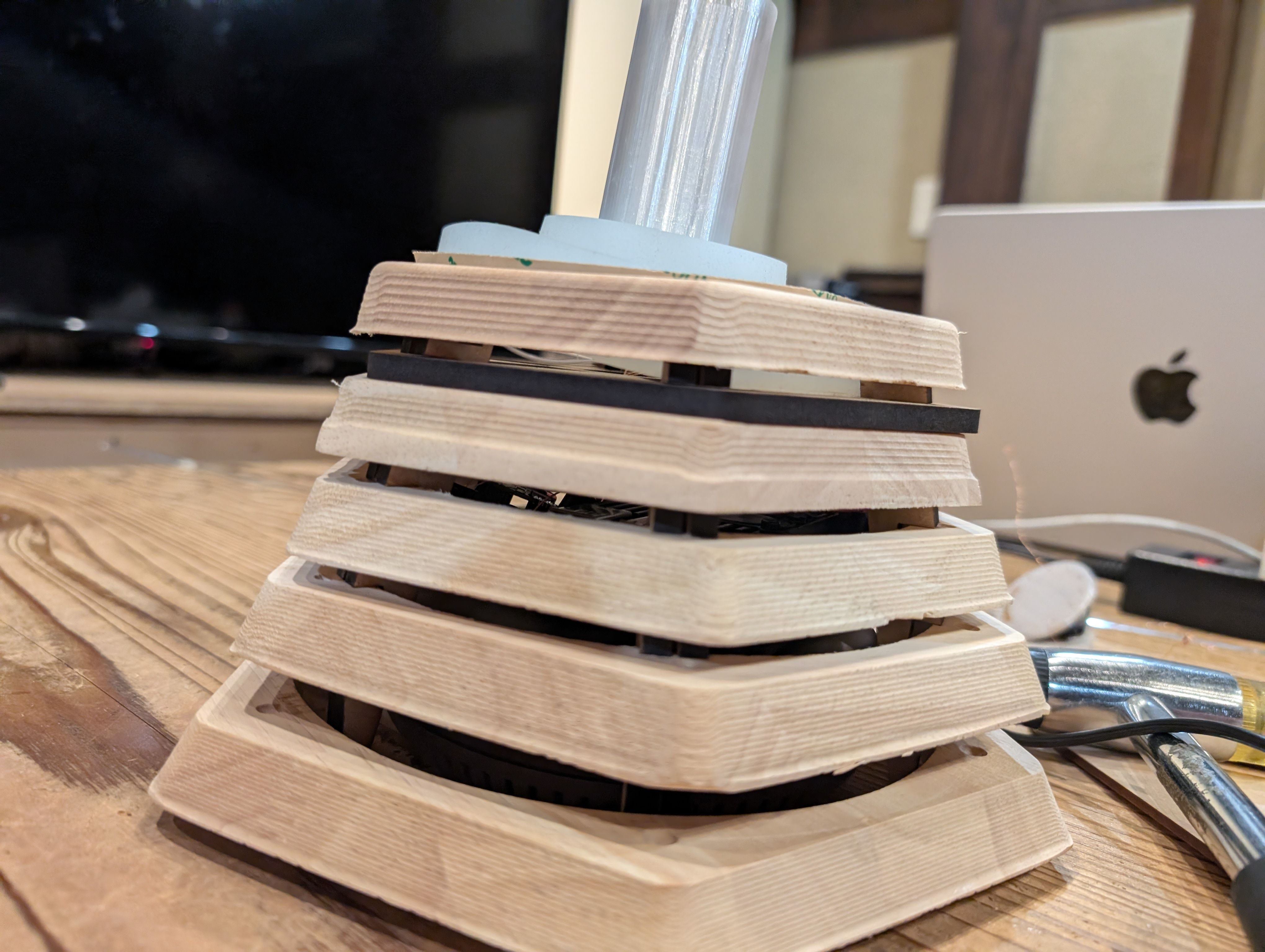
System Integration(Week 15)
- Revise schedule till June
- Design whole CAD model for my Final Project
- Assemble and check the wiring
I made schedule during Midterm, and I revised it this time. My target date is June 9th.
Also, this is the system diagram.
For first spiral, basically I'll focus on Main Function.
For the details, please see Week15 System Integration page.
Progress after week 15
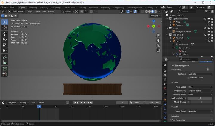
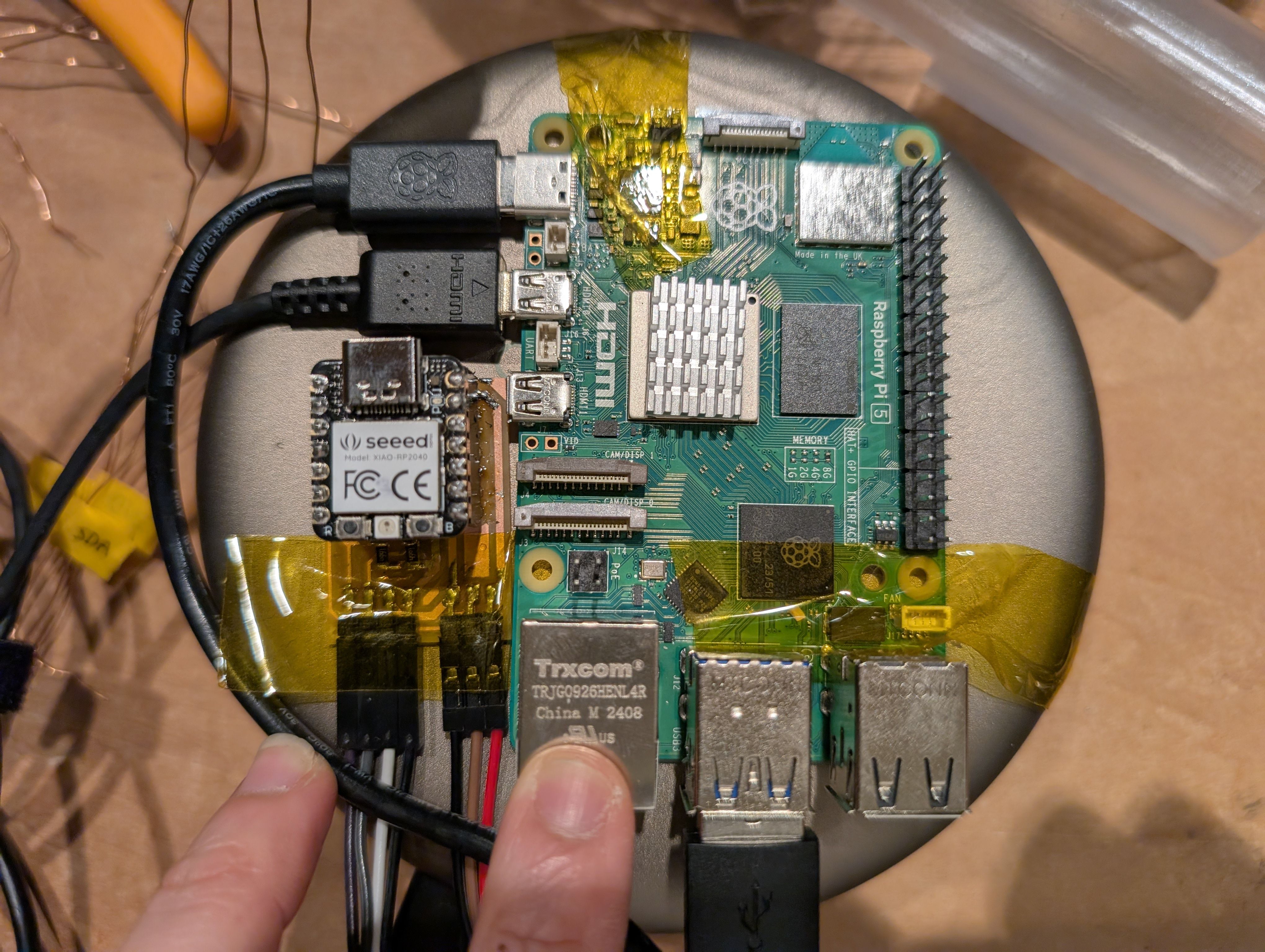
After decision about the base part, I made the whole CAD design as below.
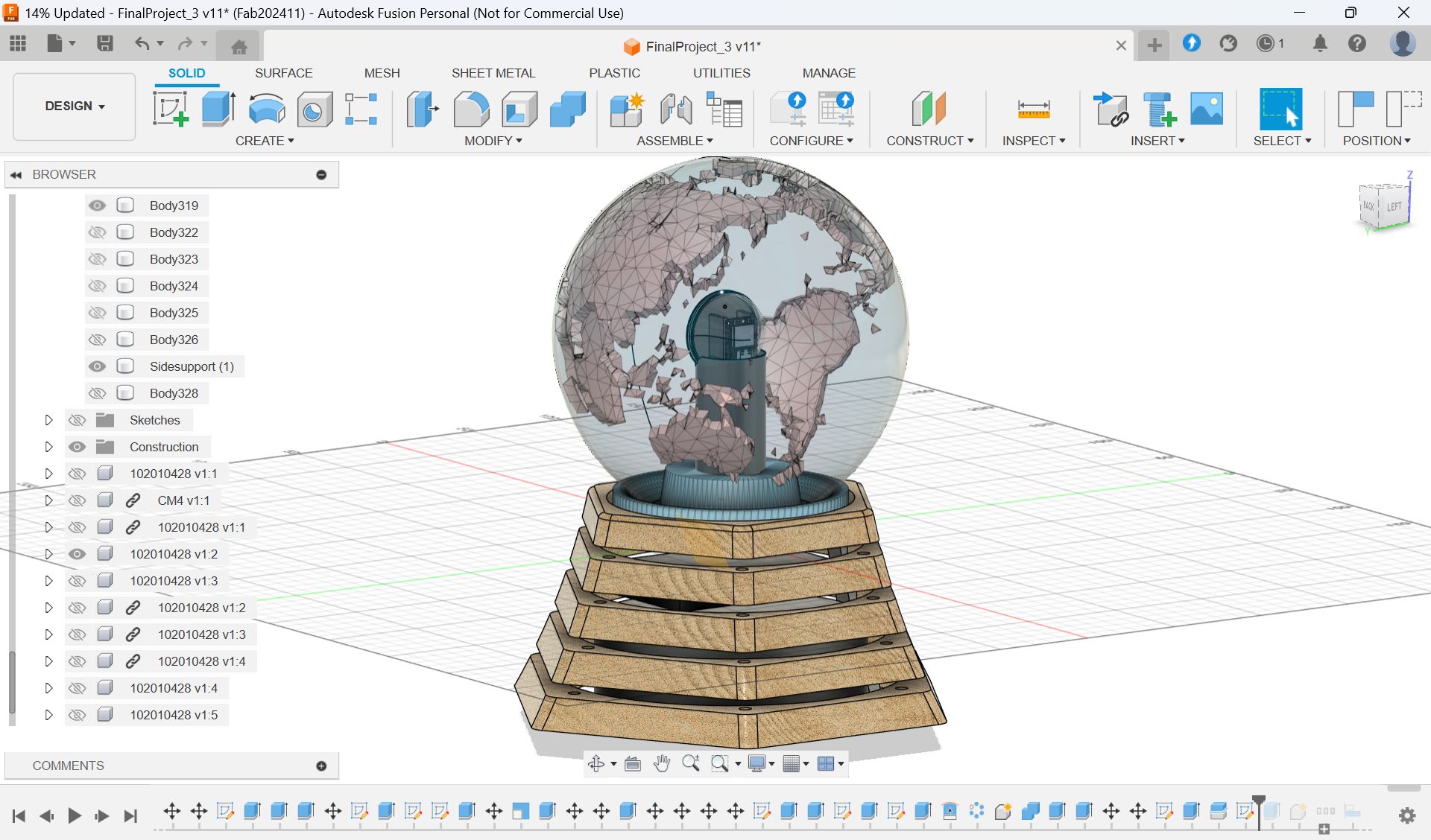
I also updated the system diagram.
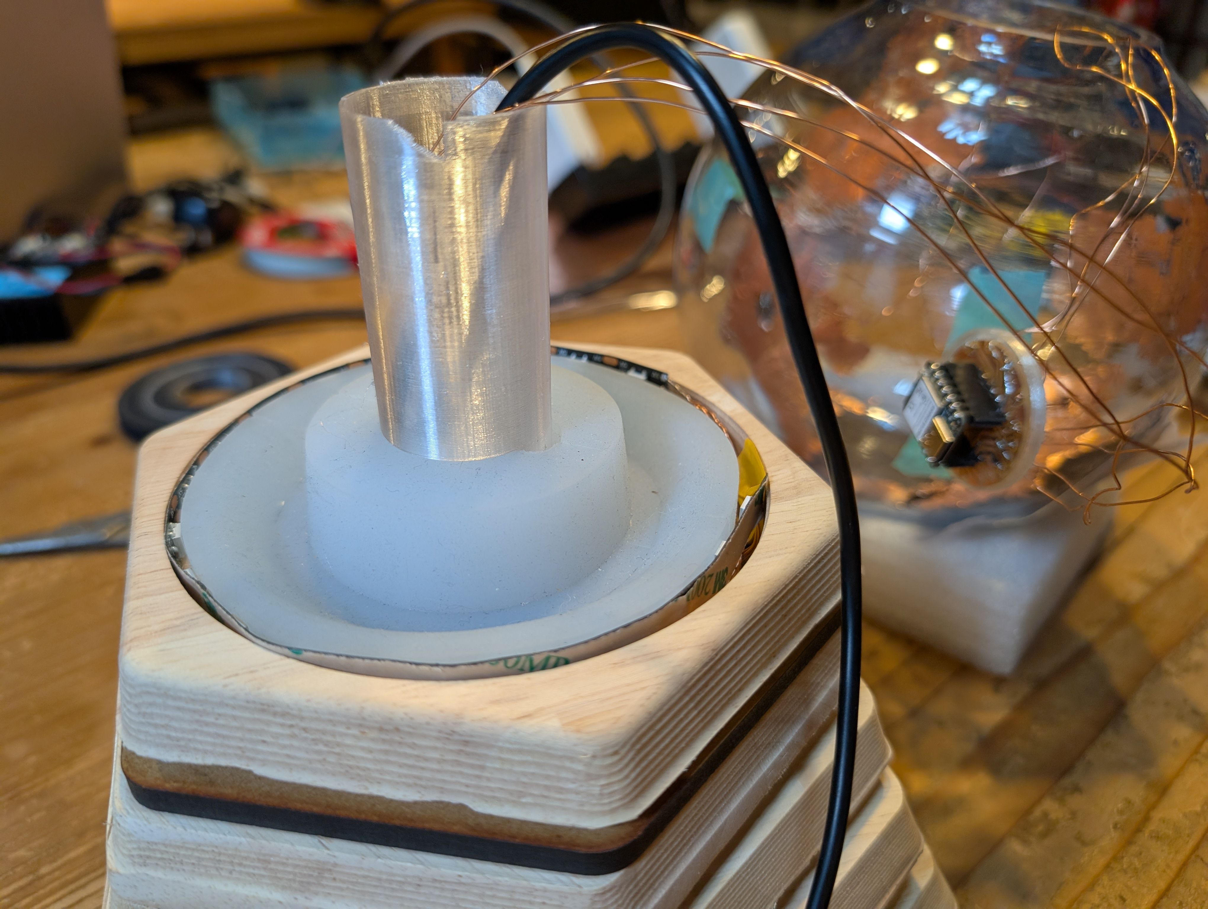
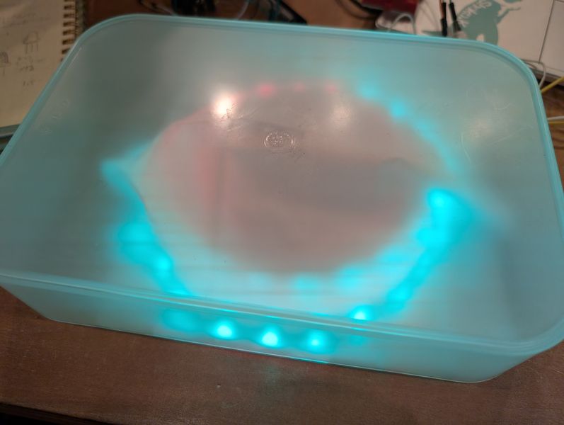
Soldered them to copper tape and attached them to the countries from inside.
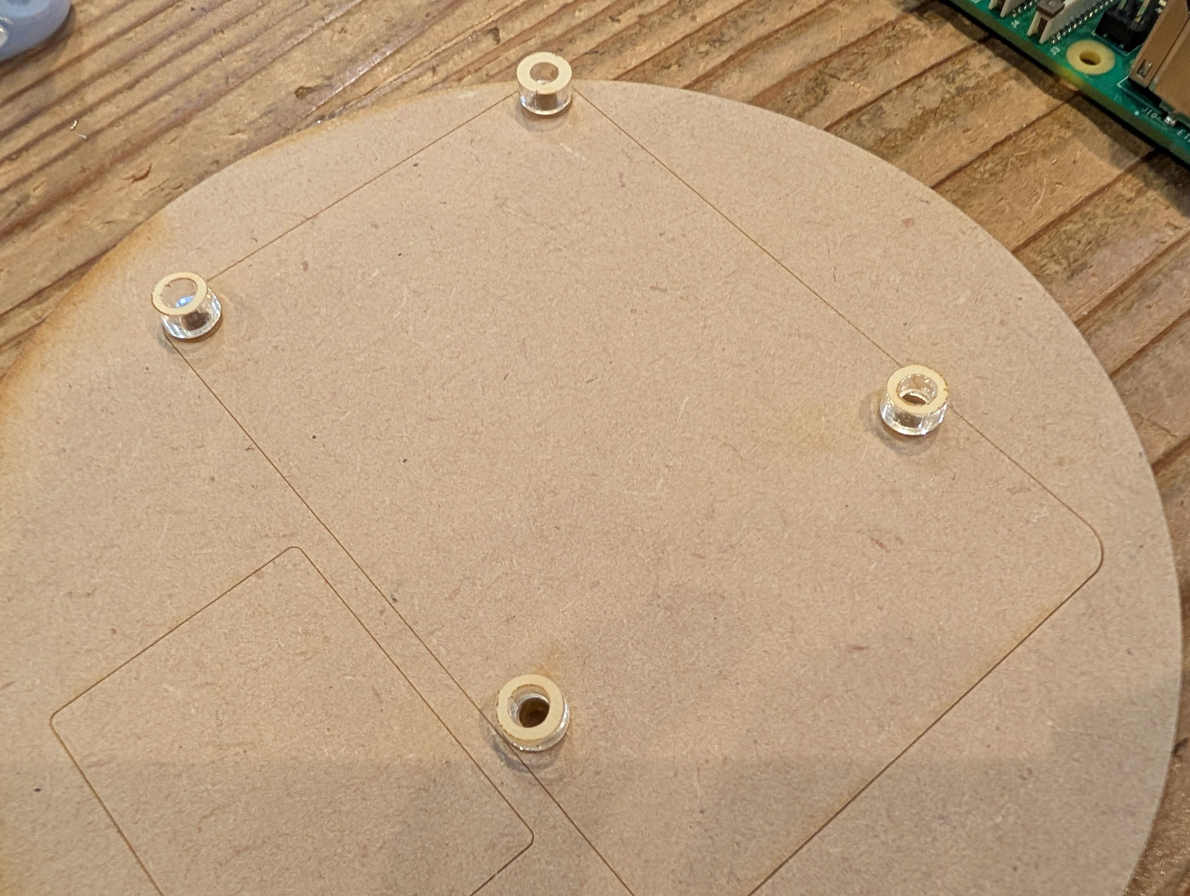
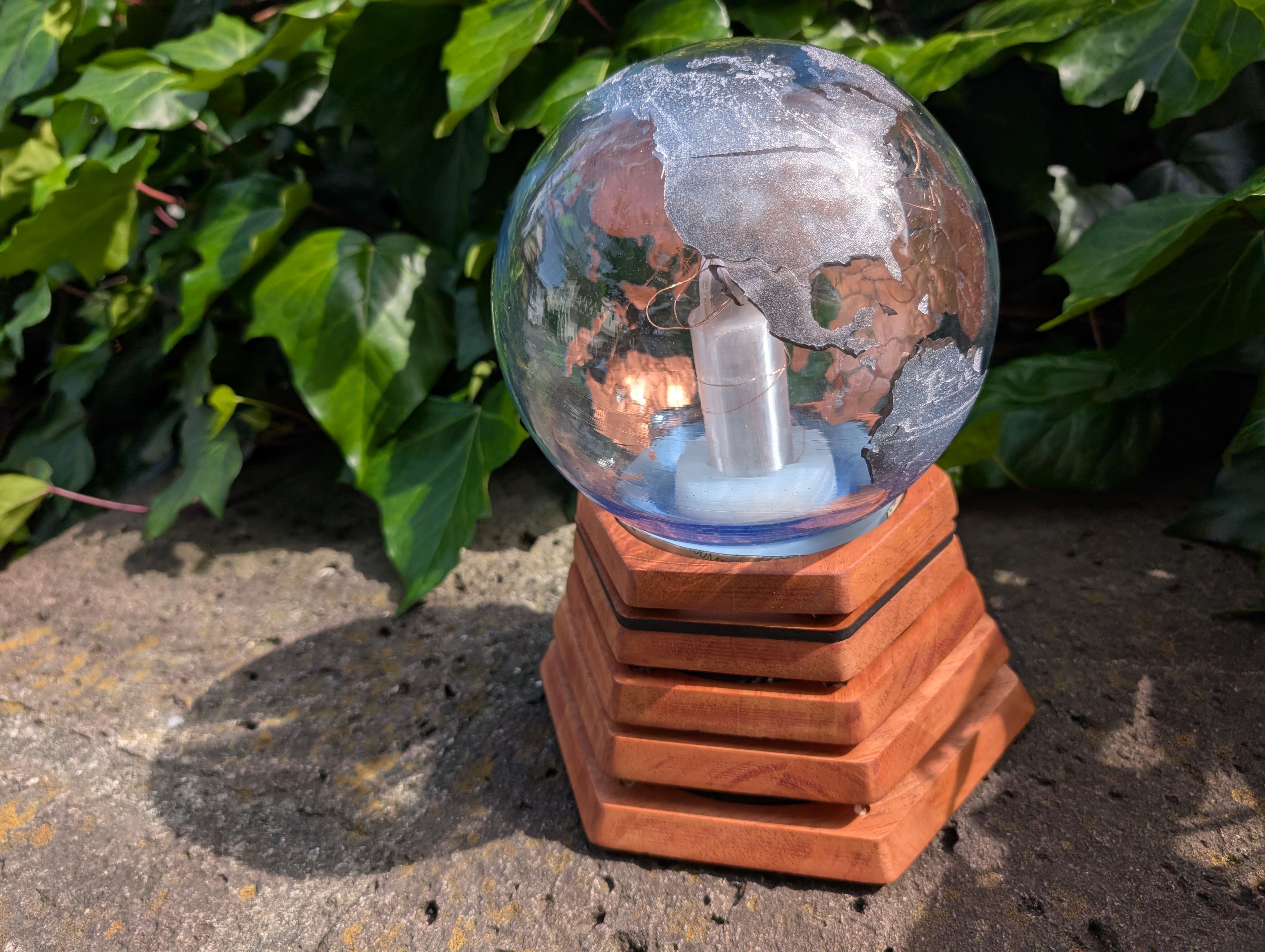
Final Result of assembling

Design Files
- Modeling
- Final Model in Fusion
(To use this model, please see the "Fablication" section parts.)
- Final Model in Fusion
- Electronics
- Fabrication
- Glass support(Molding and Casting)
- PCB Case and support(3d printing)
- Base Parts(Wood Milling)
- Base support Parts(Laser Cutting)
- Map(Vinyl Cutting)