#10 Output Devices
This week I learned how to output something with a devices.
Assignment
Group assignment
- Measure the power consumption of an output device
Individual assignment
Outcomes
What did I do this week: 1. Group Assignment
The group assignment page - week10
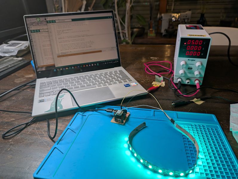
Measure the power consumption of an output device
We used an Adjustable Regulated Power Supply to measure the difference in power consumption depending on how the LEDs are connected, as well as the power consumption of the motor.
For details, please see the group page: The group assignment page - week10
What did I do this week: 2. Individual assignment
Add an output device to a microcontroller board you've designed and program it to do something
Power Supply
Power management is important when using output devices. (Large currents can also affect the human body.)
- DC motor : Controlled by 2 lines (positive, negative). Also used in Air Pomp and Liquid Pomp.
- servo motor : 3 lines (positive, negative, signal), controlled by Angle. Used when you want to control angle. Used for robot limbs, etc.
- stepping motor : 3lines (positive, negative, signal), controlled by step, used when power is needed. used to control 3D printers and lab machines.
- brushless DC motor : Fast. Only control whether to rotate or not.
- Voltage: 5V
- Current: 0.4~1.2A
Each individual NeoPixel draws up to 60 milliamps at maximum brightness white (red + green + blue). In actual use though, it's rare for all pixels to be turned on that way. circumstances, but we've been using 1/3 this (20 mA per pixel) as a gross rule of thumb with no ill effects.
(https://learn.adafruit.com/adafruit-neopixel-uberguide/powering-neopixels) - NeoPixel is marked with an arrow for the direction of data transmission, so follow that direction to connect!
Basis
V=IR, I=V/R, Power P(W) = Voltage E(V) × Current I(A)
When voltage (V) is constant, the smaller the resistance (R), the larger the current (I).
If resistance (R) is large, current (I) will be small.
In a series circuit, current (I) decreases because resistance (R) increases.
In a parallel circuit, current (I) increases because resistance (R) decreases. (Current doubles, resistance halves.)
How to determine the elements
Prepare a power supply (V) that can supply the current (I (Ampere)) required for the components (microcomputers, motors, etc.) you use.
If the voltage from the power supply is too large when using a device such as a microcontroller, measures must be taken so that the excessively large voltage does not flow as it is.
There are two ways to do this: using a Voltage Divider or a regulator.
Regulator : The voltage is always constant. Used to keep the voltage constant when the current is not constant.
Voltage Divider : Used when the voltage is small (5v, 3.3v, etc.) or the current is constant (Arduino and xiao, Raspberry Pi communication, etc.).
For example, when connecting a microcontroller, place a resistor in series in front of the microcontroller and in parallel with the microcontroller to distribute the voltage and control the voltage.
Since the resistance of the microcontroller is large, such as 1MΩ, we want to reduce the current. (If the resistance value is fixed, the voltage will increase as the current flows.)
PWM: Pulse Width Modulation
Used for Analog Write when a DAC cannot be used. When controlled digitally, the pulse size cannot be changed, so the pulse duration can be controlled to make it appear as if it is controlled analog (strength or weakness).
Output Devices
Various types of output devices are shown below.
Motors
Output - NeoPixel
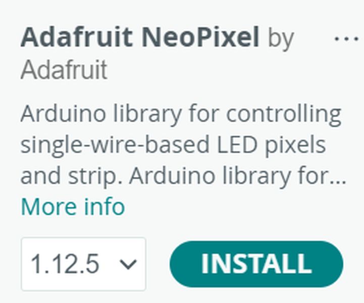
I wanted to make it glow when touched, so I decided to try LEDs.
This time, I decided to use NeoPixel.
First of all, I decided to connect it to ESP32S3, which I tried a touch sensor last week.
To use NeoPixel, please refer to the following:
https://learn.adafruit.com/adafruit-neopixel-uberguide/the-magic-of-neopixels
To use NeoPixel, I installed the following library in ArduinoIDE.
https://github.com/adafruit/Adafruit_NeoPixel
The library had various sample codes, so I decided to try different ways of making it glow.
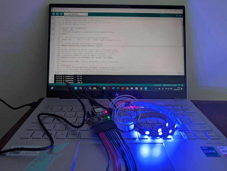
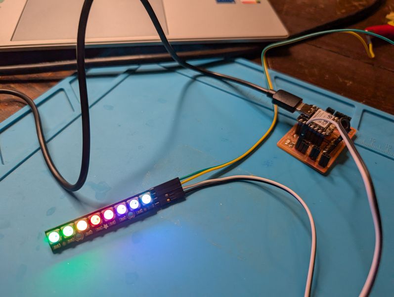
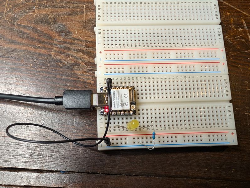
First, I tried it on a breadboard.
At first, it glowed well.
However, at some point it stopped glowing properly, and since this problem has not been solved, I decided to continue testing with xiaoESP32-C3. (It took quite a lot time to debug the xiaoESP32-S3. Details are described later.)
PCB Design
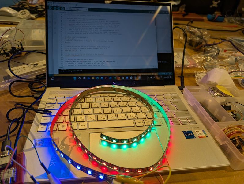
In order to have a single board that glows when touched, I created a board that can connect the MPR121 and NeoPixel. Also, the previous board had become weak due to repeated plugging and unplugging, so I redesigned the board with a through socket.
Schematic design (some unnecessary LEDs remain due to last week's diversion)
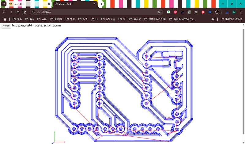
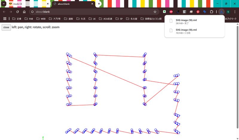
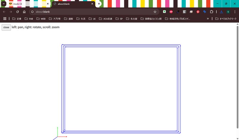
PCB Design (Design Rule is the same as last week)
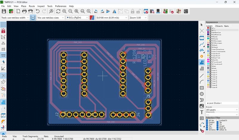
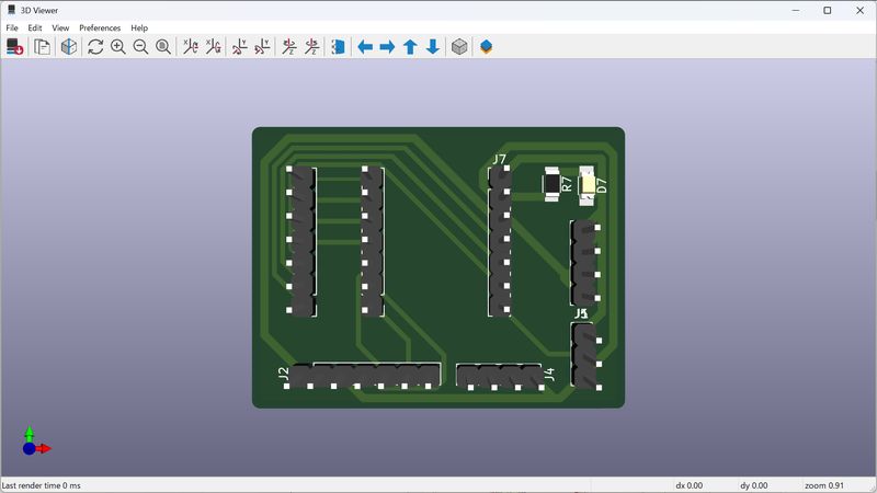
Produced the following 3 data from mods.
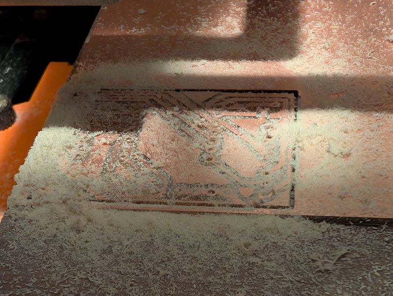
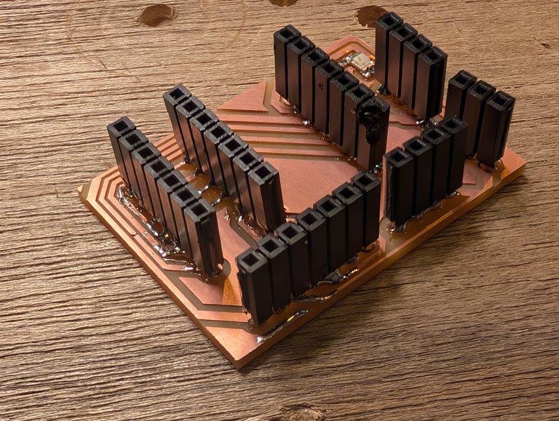
When I connected NeoPixel, I was able to make them light up.
However, after milling it, I plugged it in and it didn't work, and then I realized (with Nagano-san's advice) the pinout on the MPR121 was reversed.
Also, the GND pin was half blocked when the MPR121 was connected.
Light Control - coding
I tried to see what would change if I changed the code "simple" and the code "strandtest".
Change the speed
#define DELAYVAL 50
Change the color
pixels.Color(0, 0, 0) //no light
pixels.Color(255,255,255) //bright white
pixels.Color(1,1,1) //weak white
At first the order of R,G,B in the code was wrong.
There seem to be several types of NeoPixel, and I tried several patterns (NEO_RGB (colors reversed), NEO_RGBW (glowing like a bug), etc.), and this NeoPixel is..,
NEO_BGR !!!
Now I can specify colors in the order R,G,B.
I also tried several light patterns.
I edited the contents of the variable Wheel in various ways to change the colors as follows.
Blue gradient
return strip.Color(0, 0, WheelPos * 3);
Green gradient
return strip.Color(0, WheelPos * 3,0);
Red monochromatic gradient (dazzling)
return strip.Color(WheelPos * 3, 0, 0);
Color-to-color gradient
   return strip.Color(255 - WheelPos * 3, 0, WheelPos * 3); //blue to red
    return strip.Color(0, WheelPos * 3, 255 - WheelPos * 3); //green to blue
    return strip.Color(WheelPos * 3, 255 - WheelPos * 3, 0); //red to green
I tried with this code.
#include <Adafruit_NeoPixel.h>
   #ifdef __AVR__
     #include <avr/power.h>
   #endif

   #define PIN 20

   Adafruit_NeoPixel strip = Adafruit_NeoPixel(20, PIN, NEO_BGR + NEO_KHZ800);

   void setup() {
     strip.begin();
     strip.setBrightness(10); // set brightness
     strip.show(); // Initialize all pixels to 'off'
   }

   void loop() {
    rainbow(100);
    }


   void rainbow(uint8_t wait) {
     uint16_t i, j;

     for(j=0; j<256; j++) {
       for(i=0; i<strip.numPixels(); i++) {
         strip.setPixelColor(i, Wheel((i+j) & 255));
       }
       strip.show();
       delay(wait);
     }
   }

   uint32_t Wheel(byte WheelPos) {
     WheelPos = 255 - WheelPos;
     if(WheelPos < 85) {
       return strip.Color(255 - WheelPos * 3, 0, WheelPos * 3);
     }
     if(WheelPos < 170) {
       WheelPos -= 85;
       return strip.Color(0, WheelPos * 3, 255 - WheelPos * 3);
     }
     WheelPos -= 170;
     return strip.Color(WheelPos * 3, 255 - WheelPos * 3, 0);
   }
I would like to try a few more patterns.
Also, with LEDs, we need to design Mode transitions.
Programming is needed to change the way the LEDs light up when a switch is pressed, when a touch is made, when the power button is turned off, and so on.
Interaction with Input
In the "buttoncycler" test code, I was able to test the behavior of the light glowing when a button is pressed.
However, when I connected the MPR121 to the NeoPixel, it was not recognized properly, and I have not yet been able to test the glow when tapped.
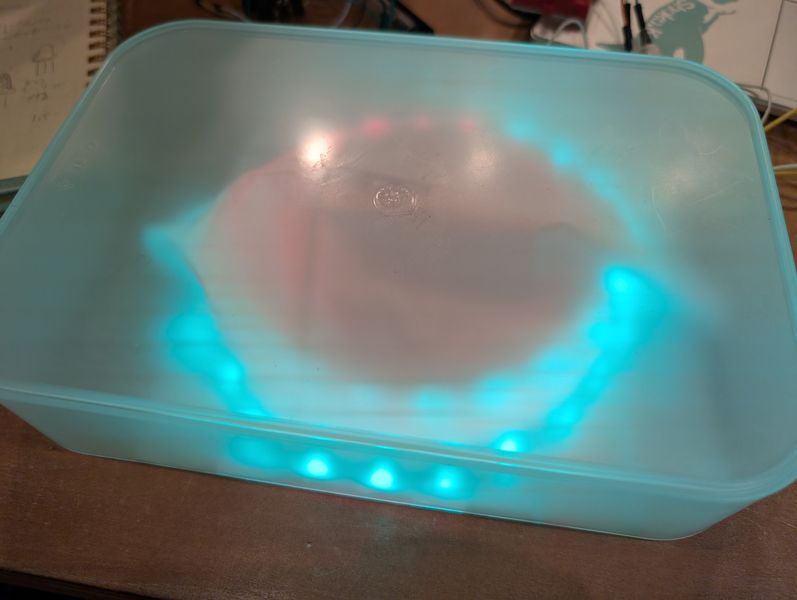
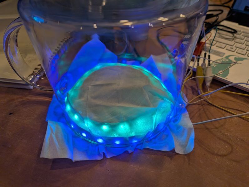
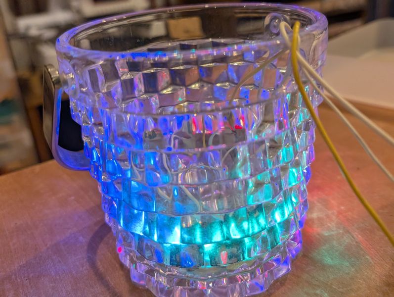
Appearance
I tried various ways of showing it.
- Covering with paper
- Covered with a matte plastic case
- Put it inside a glass
- Putting it inside an uneven glass

Other possible methods
- Cover with a silicone cover
- Attach beads, etc.
Debug
I tried the following solutions to the problem of NeoPixel not glowing on xiaoESP32-S3.
- Check the continuity with Multimeter (sound) : Check the circuit
- Check if the signal line is receiving voltage: check the circuit.
- Change the power supply (connect a capacitor): check the power supply.
- Connect LEDs on a breadboard one pin at a time and see if they light up: check the signal on each pin
- Change microcontroller (other s3, c3, RP2040, etc.) : Check microcontroller
- Change NeoPixel : Check NeoPixel
- Change USB cable : Check the cable
- Change PC: check PC/USB port
As a result, there were some cases that NeoPixel did not work only on S3 other than mine, although it sometimes glowed when I changed PC and cable, and the cause remains unknown.
Outcomes
This week was a week of learning a lot about electronic circuits. I need to pay attention to the power supply, especially when connecting a projector in the future.
I would like to do more research on NeoPixel, because I think there are more ways to express it.
Remaining issues - things to check
Power supply for the entire project. How to decide it
Projector current and voltage.
Why the NeoPixel stopped working on the xiaoESP32-S3
Why the NeoPixel and MPR121 didn't connect properly
How to make it light up when tapped
How to make the NeoPixel light up (pattern)
(Remaining from last week)
How the tap works. Which mechanism to use (starting with the small ones)
Differences in how to control taps for large and small areas