#16 WildCard
This week I tried Wood Milling
Assignment
- Design and produce something with a digital process: Wood Milling
(incorporating computer-aided design and manufacturing) not covered in another assignment, documenting the requirements that your assignment meets, and including everything necessary to reproduce it. - Other processes
Outcomes
What did I do this week: Wood Milling
Requirements
Process: 3D Wood Milling
Requirements:
- To cut out the wood while milling. Set up optimal paths for this purpose.
- Smooth finish
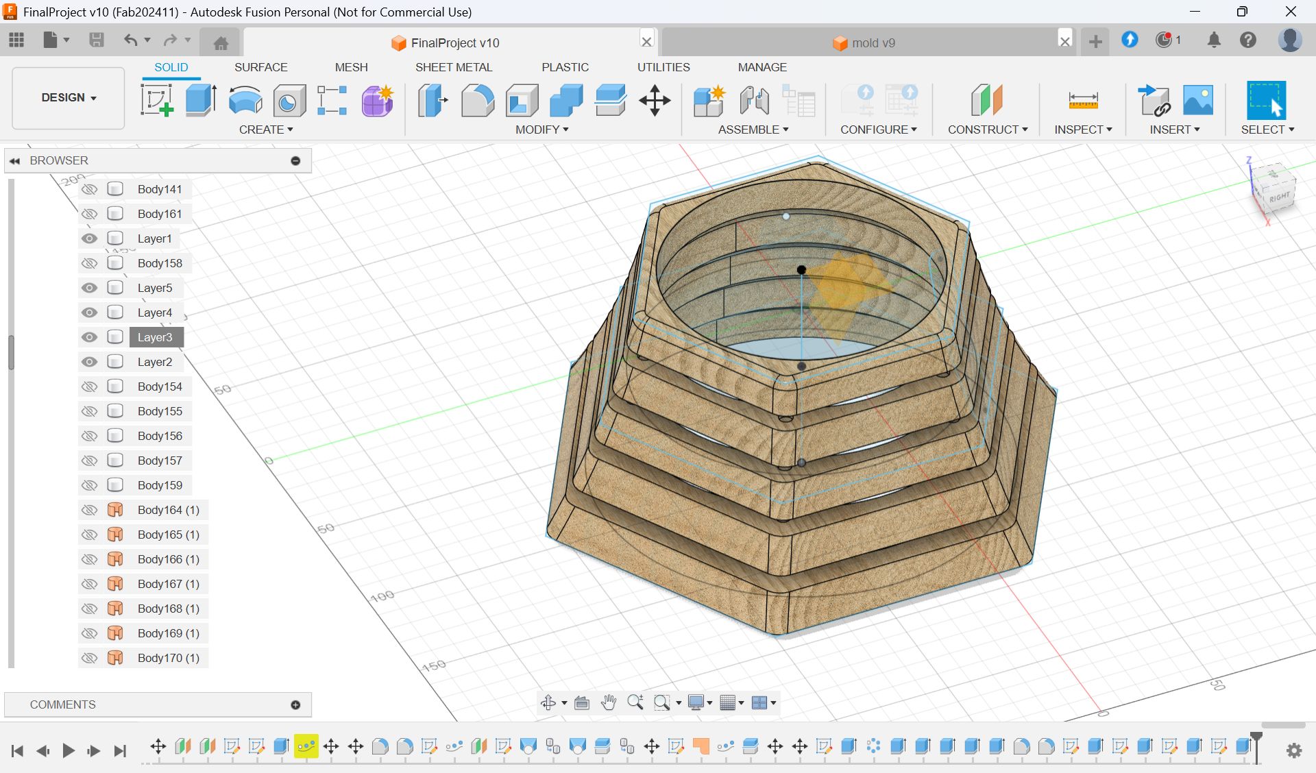
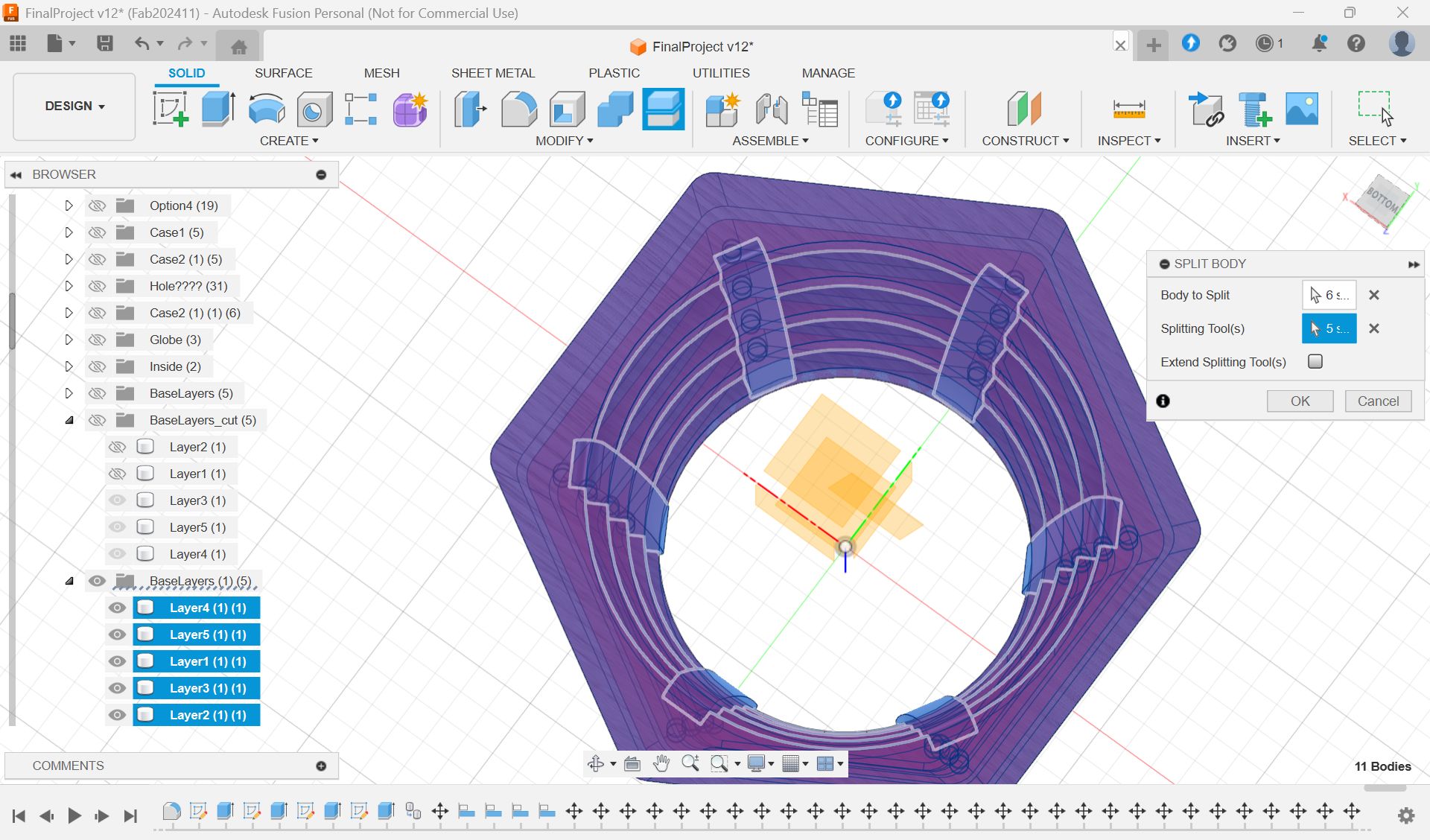
Design (Fusion)
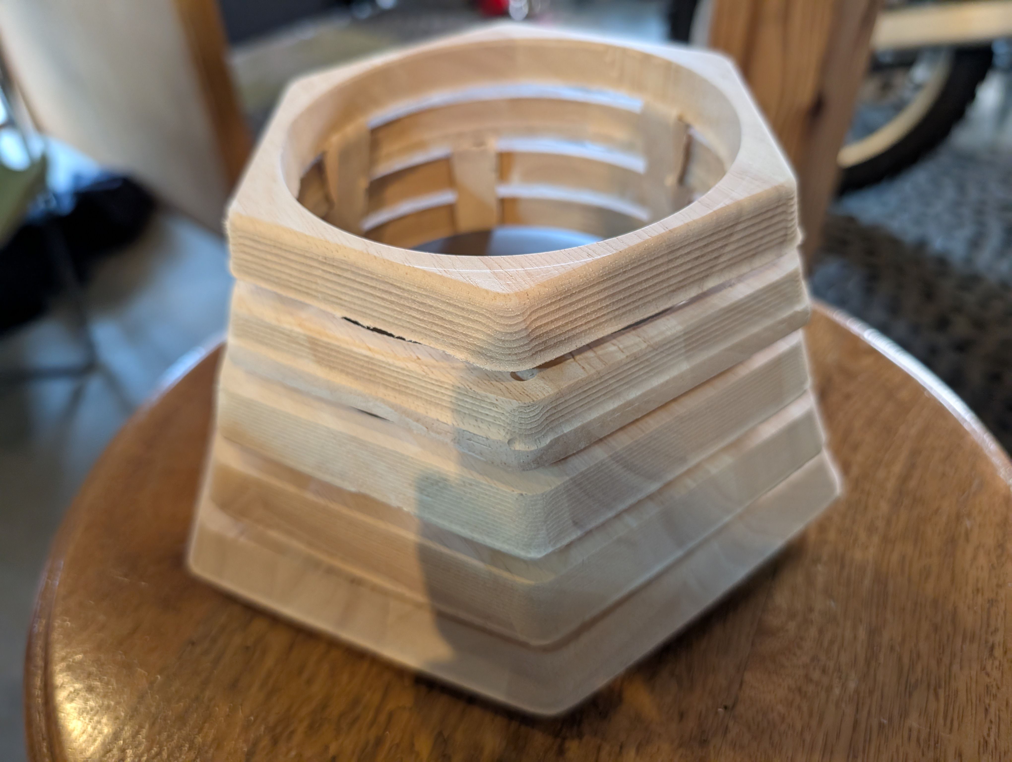
Design requirement: to cut a smooth finished block out from a single piece of wood.
Initially, I was going to make a box shape and cut it out from a block of wood,
However,
- It would be a waste to dig out the entire center parts of wood (= unusable later)
- Digging takes too much time
- It is difficult to find a large block of wood
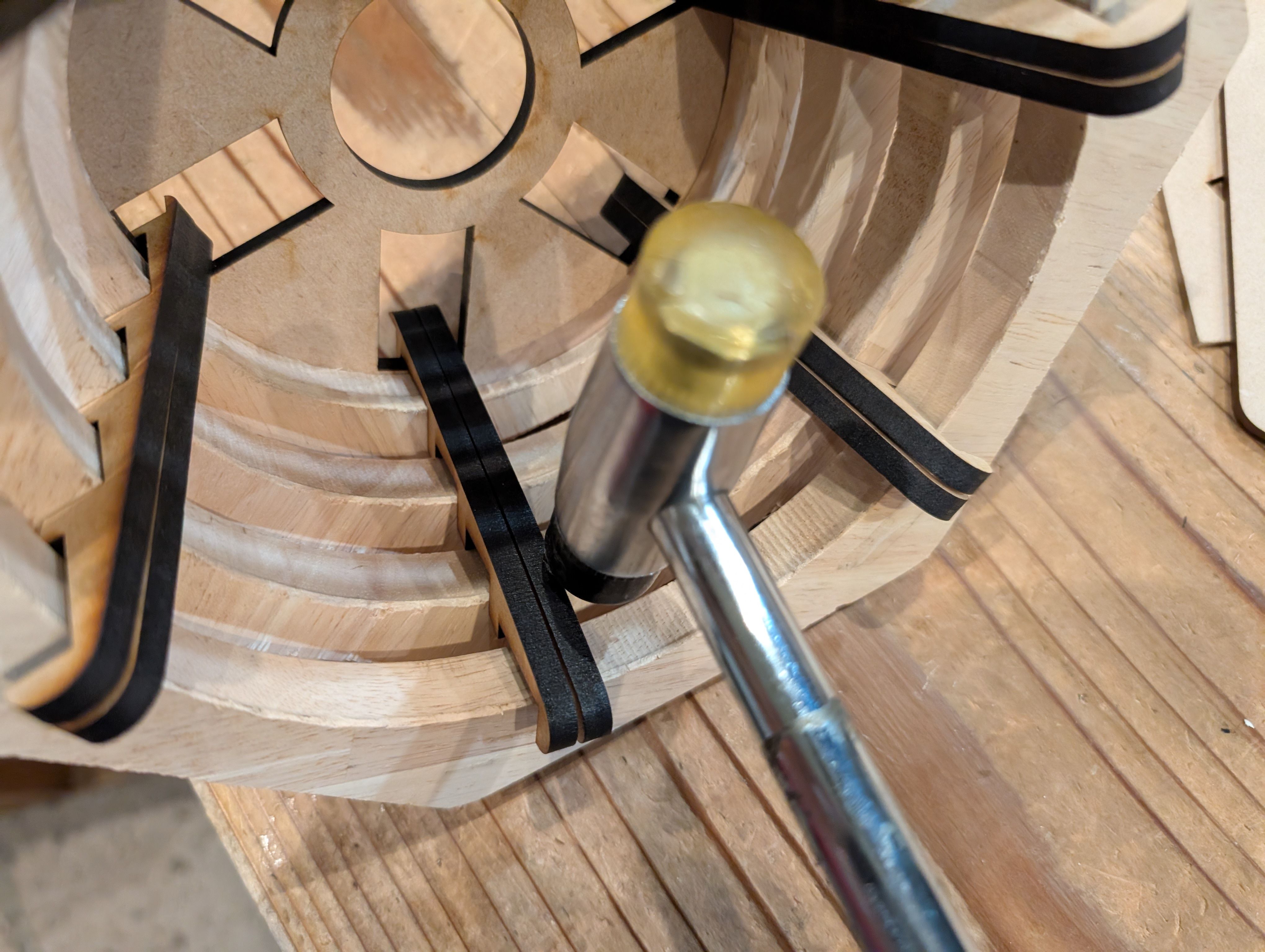
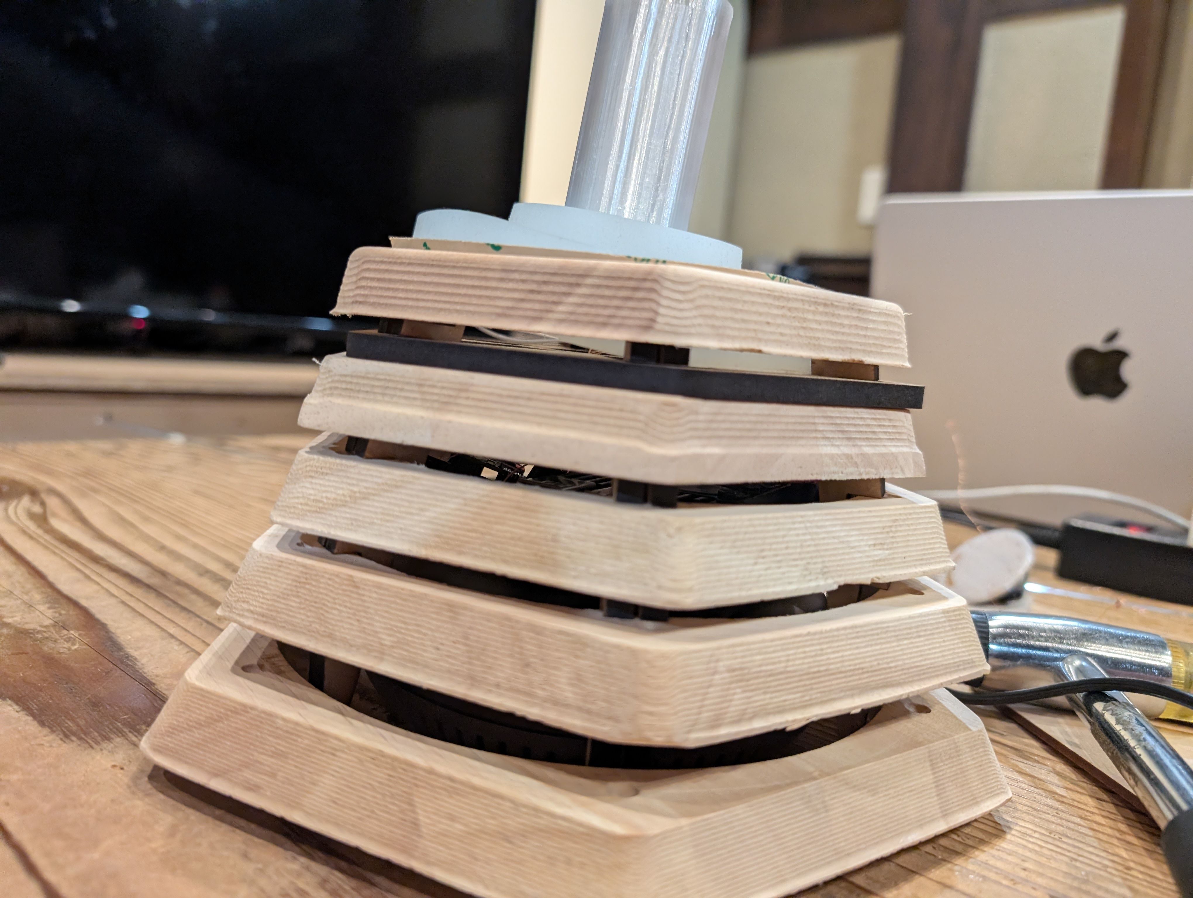
For these reasons, I modified the design to combine several wooden boards.
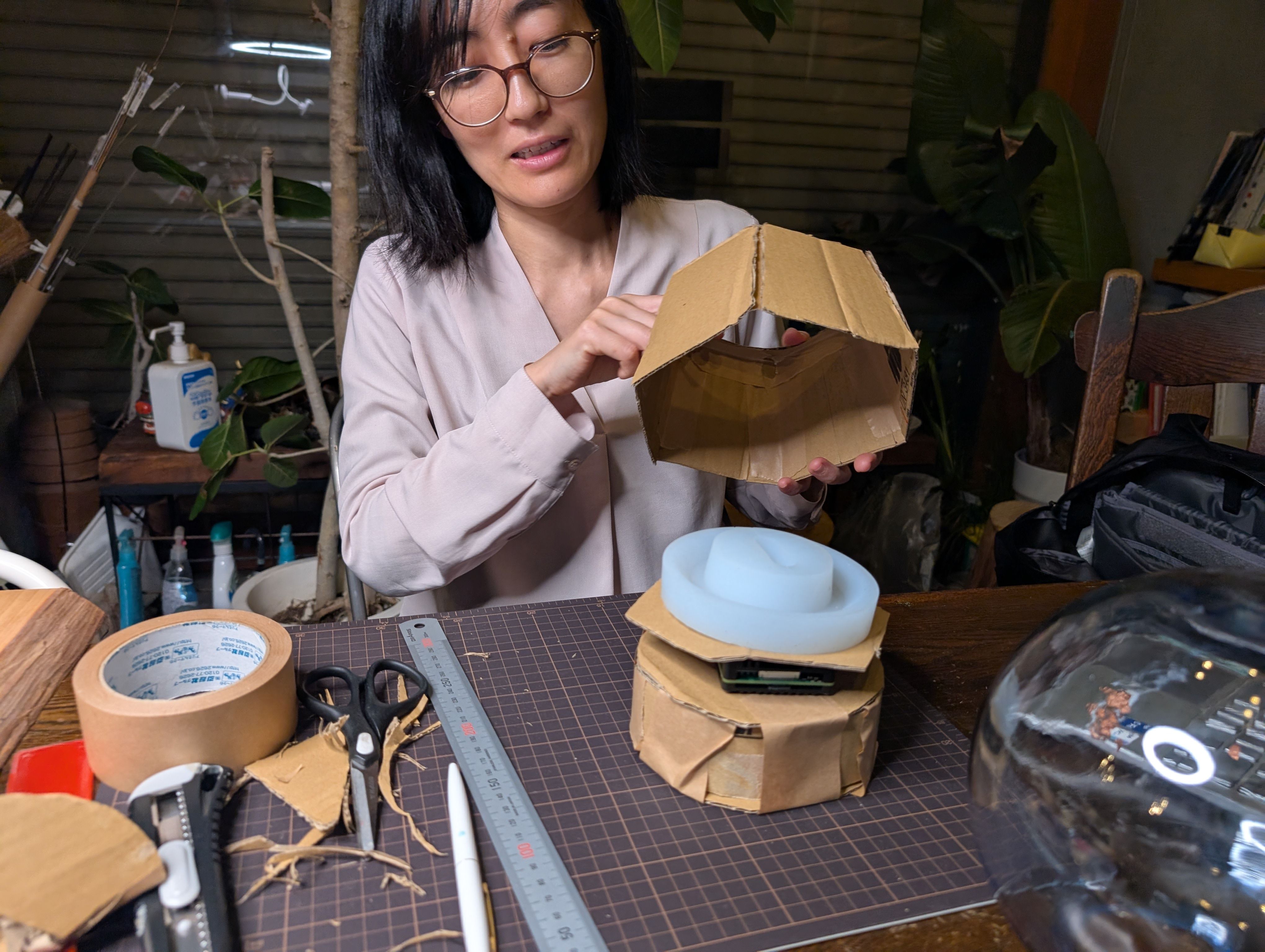
In addition, due to the problems of heat exhaust and image projection of the projector,
we considered a method that would have a good design but also leave a gap between
the projector and the projector.
As a result, the following design was obtained.
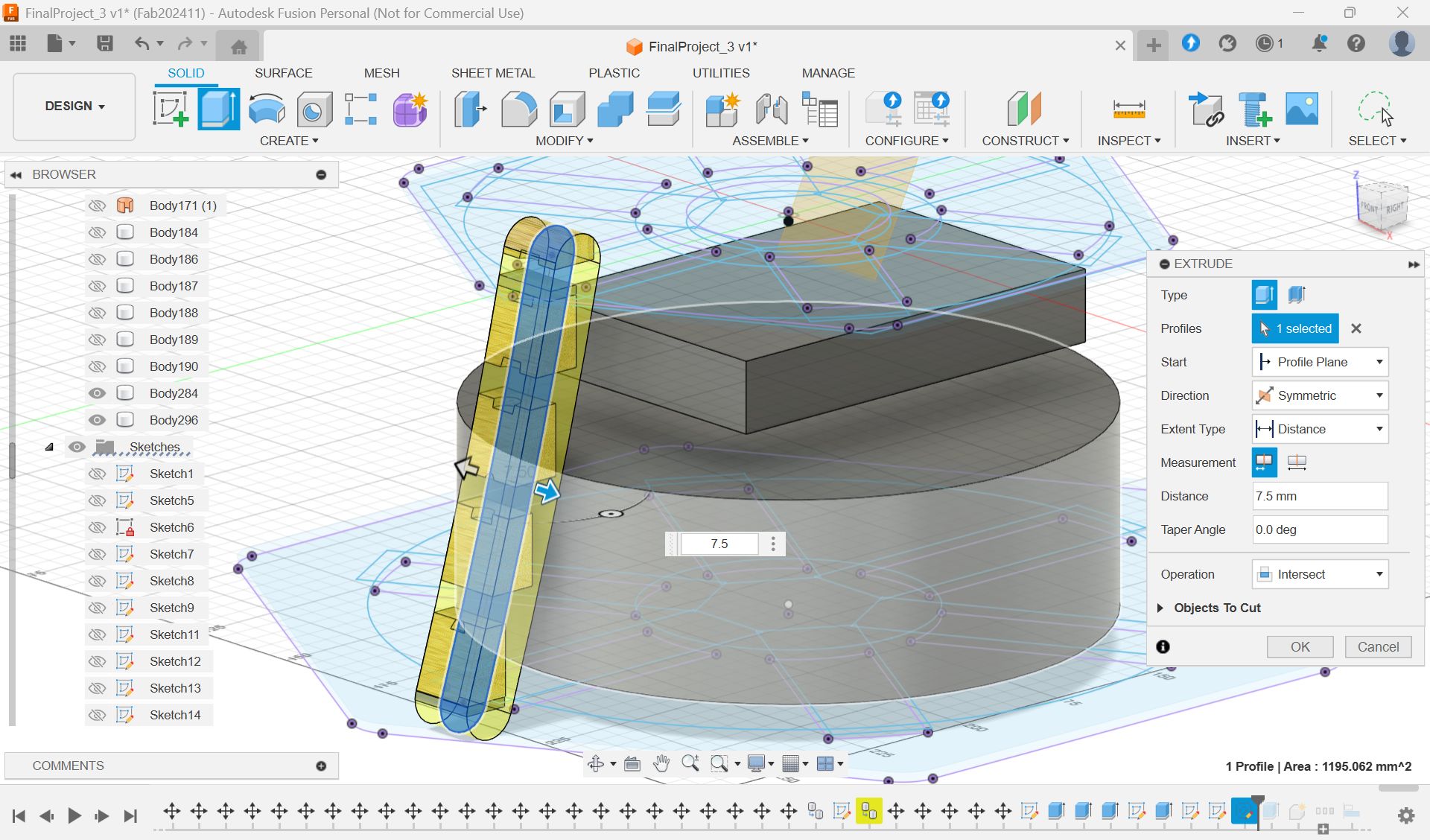
As for the parts connecting these trees, I tried to use CNC machining at first, but it
was too thin to cut out, so I decided to use laser cutting.
*Design of the connection part
Tool Path
Path requirement: Set up a tool path to cut out a block from a piece of wood while
cutting it.
In this process, I had the most difficulty in finding the best way to create the tool
path suitable for the above.
Since I needed to cut out the tree, not just dig it out, I spent a lot of time trying
to figure out how it should be set up.
Fusion or VCarve?
I couldn't find documentation to do both milling and cropping, so I went back and forth
between the two softwares to find a way to set it up successfully. As a result, I
used VCarve to set up the settings.
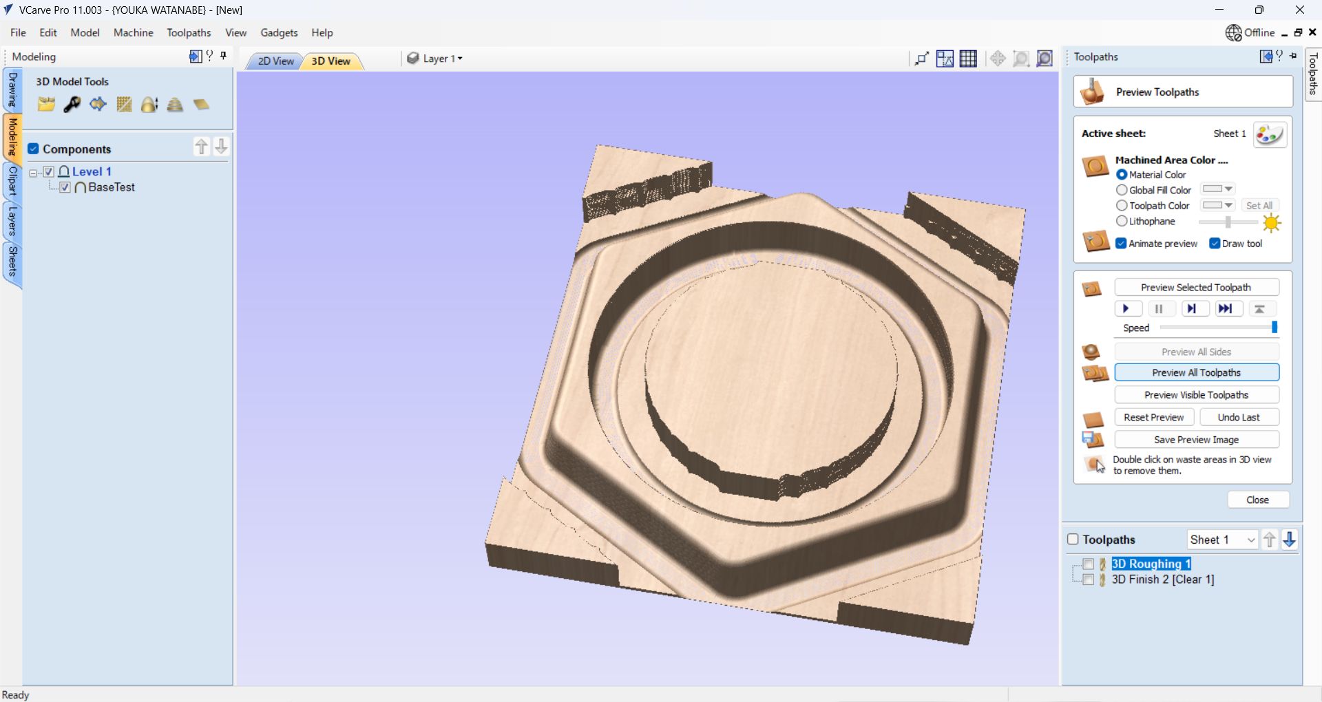
Settings in VCarve
Toolpath:
3D roughing for rough cut
3D Finishing for finish cut
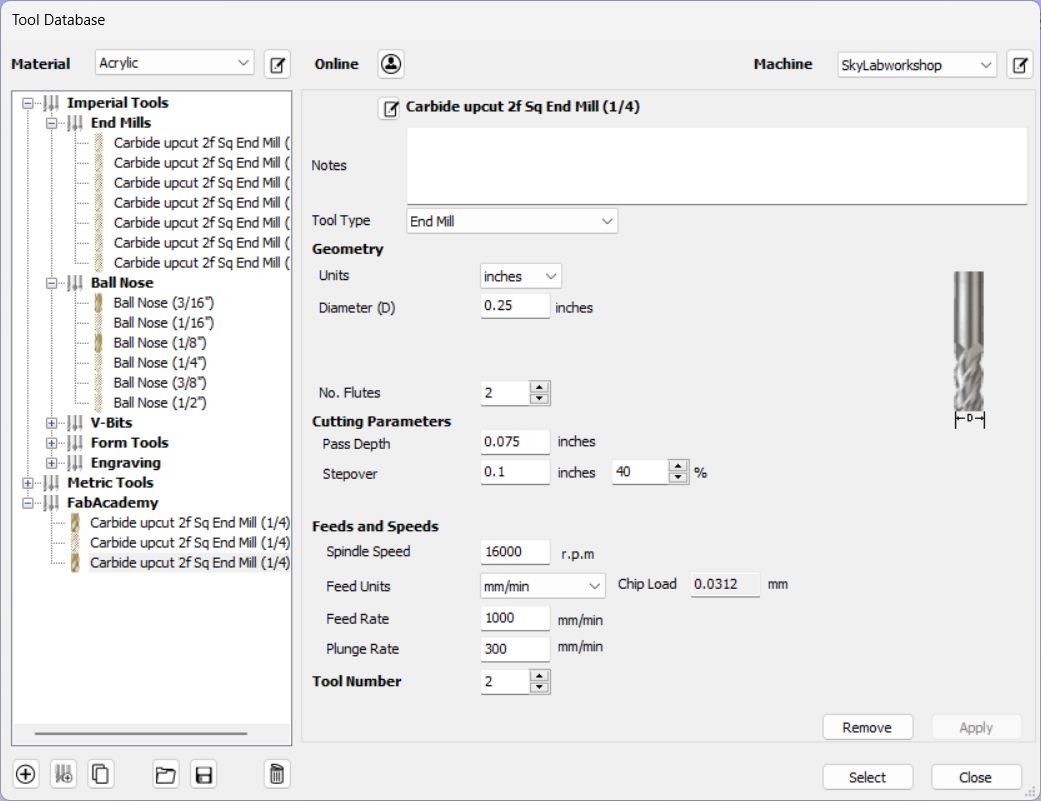
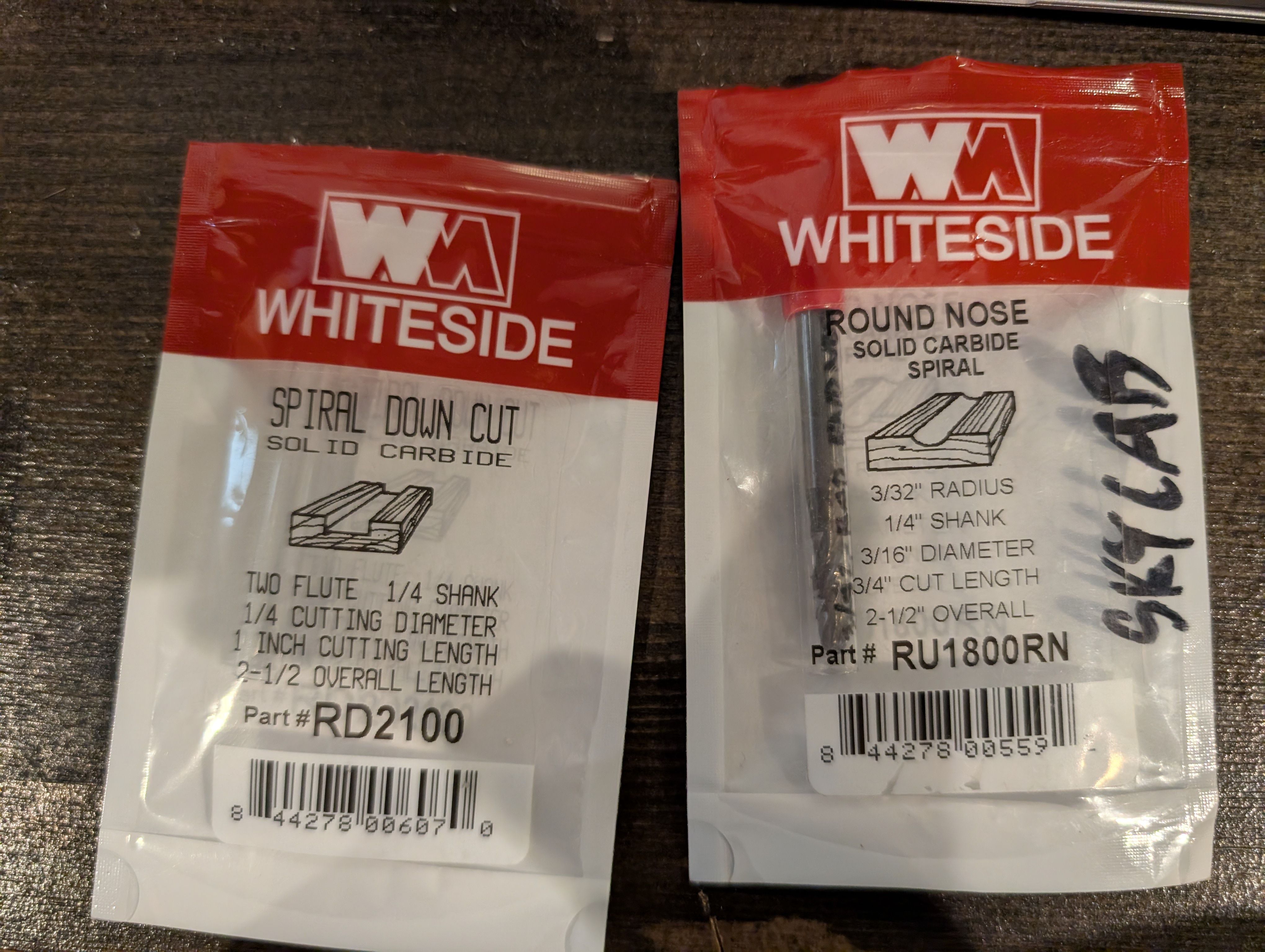
Tool:
Roughing:
Spiral Down Cut 2 Flute, 1/4 shank, 1/4 cutting diameter
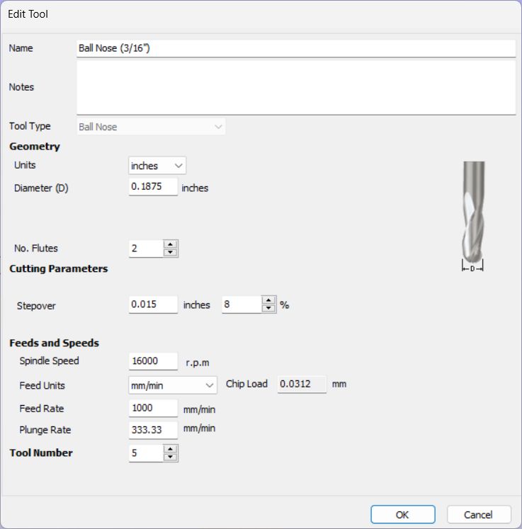
Finishing:
Round Nose , 3/32 radius, 1/4 shank, 3/16 diameter
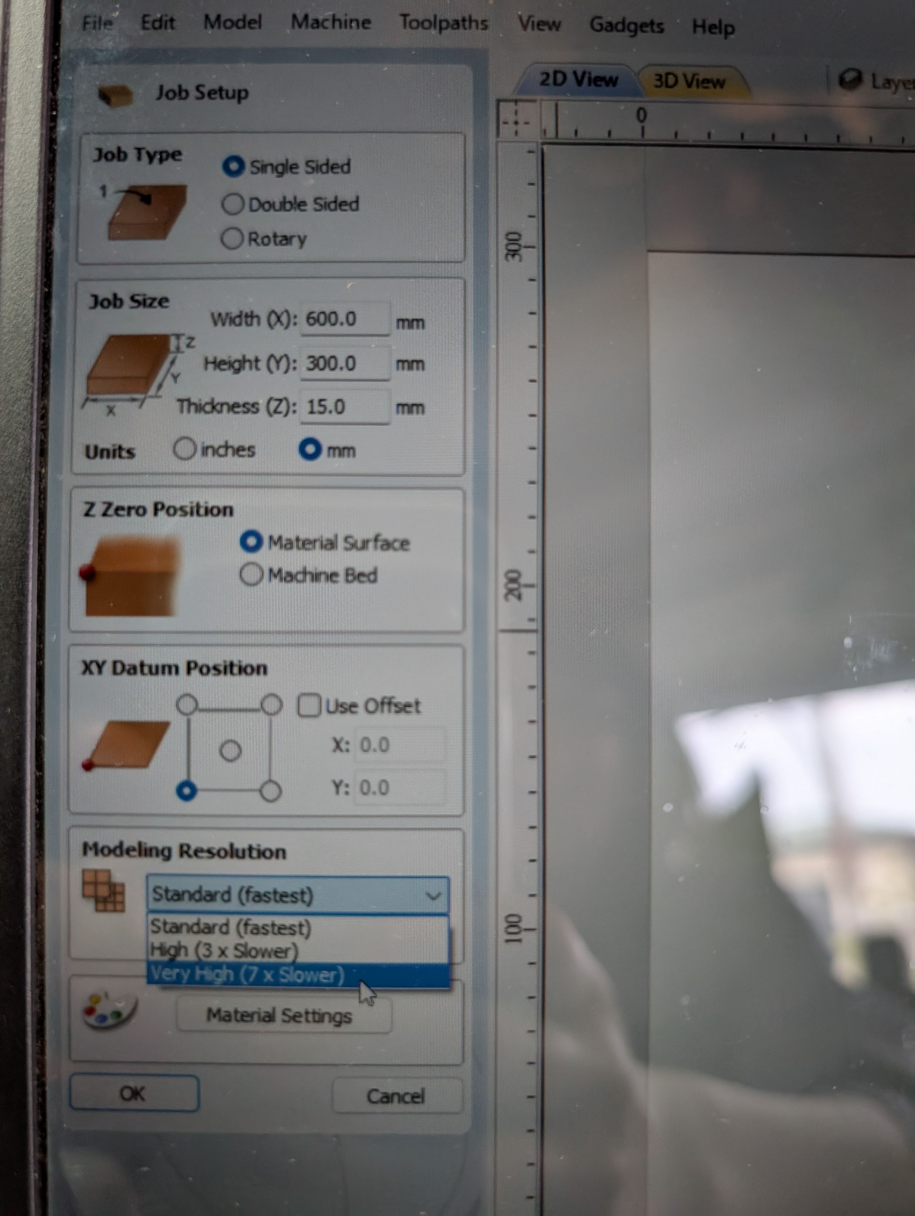
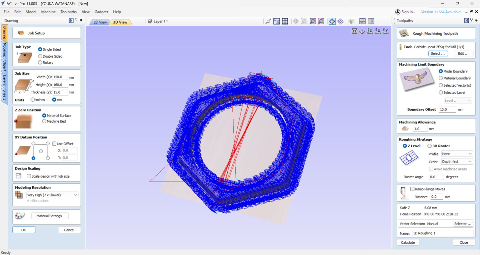
Job Setup
Single sided Job size: set same as material size
Offset X,Y = 0,0
Modeling Resolution: Very High
Material Settings: Canadian Maple
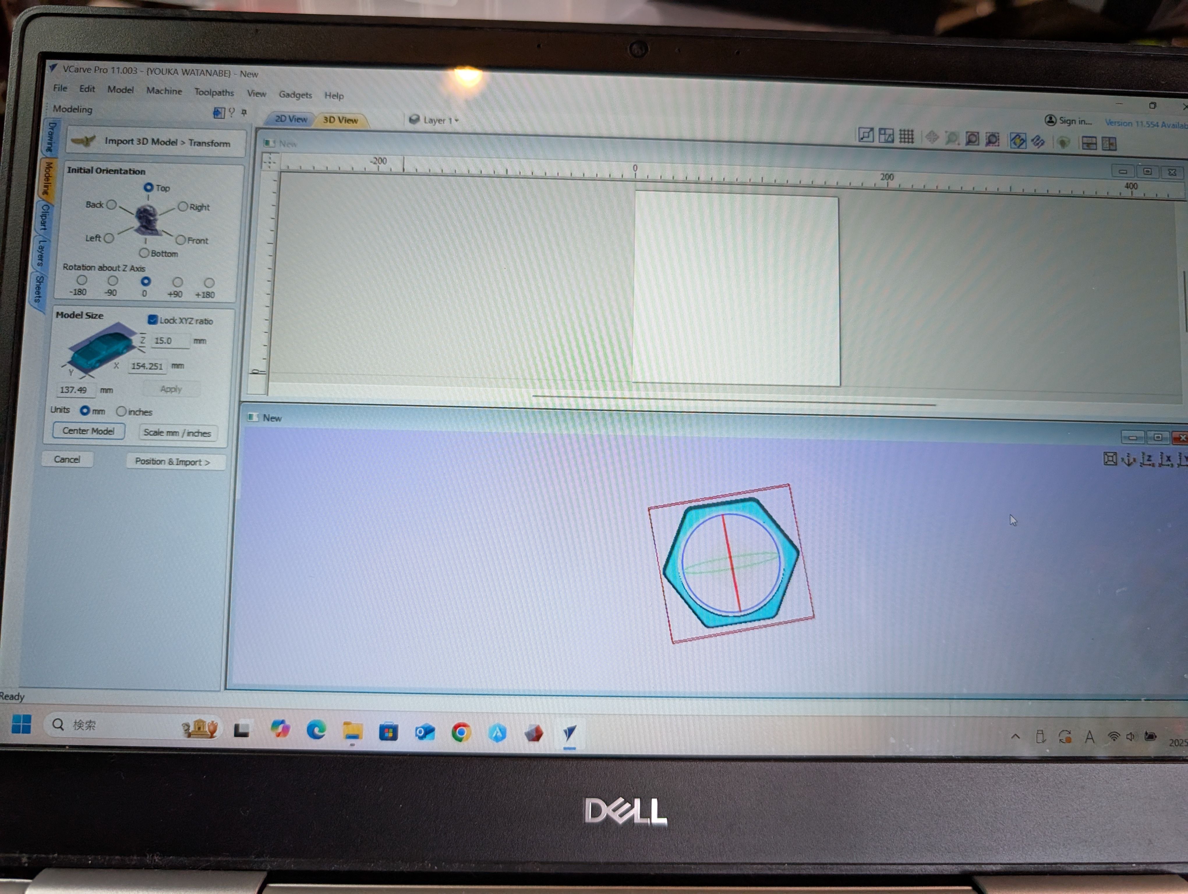
Import 3D Model from "Import 3D model" menu in "Modeling" tab
Center model
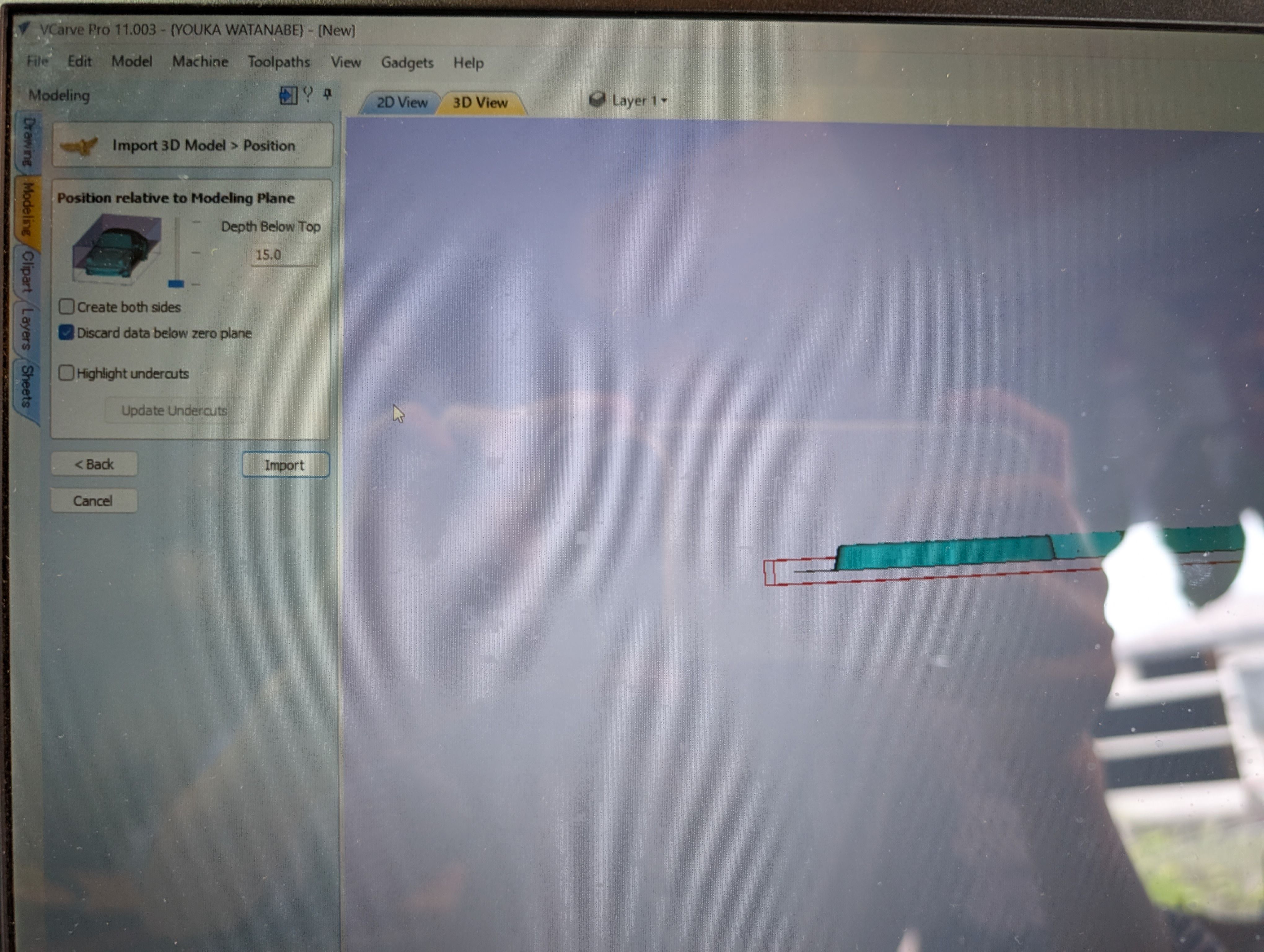
Position relative to modeling Plane - Depth Below Top: same as material thickness(since
this is not double sided design)
Setting for Roughing tool
Setting for Finishing tool
Roughing path setting
Machining Limit Boundary: Same as above.
Model Boundary, Boundary offset: 10.0mm(Bigger than tool diameter(6.5mm))
Finishing path setting
Machining Limit Boundary: Model Boundary, Boundary offset: 10.0mm(Bigger than tool
diameter(6.5mm))
Model Boundary, Boundary offset: 10.0mm(Bigger than tool diameter(6.5mm))
Strategy: Offset, Cut Direction: Climb
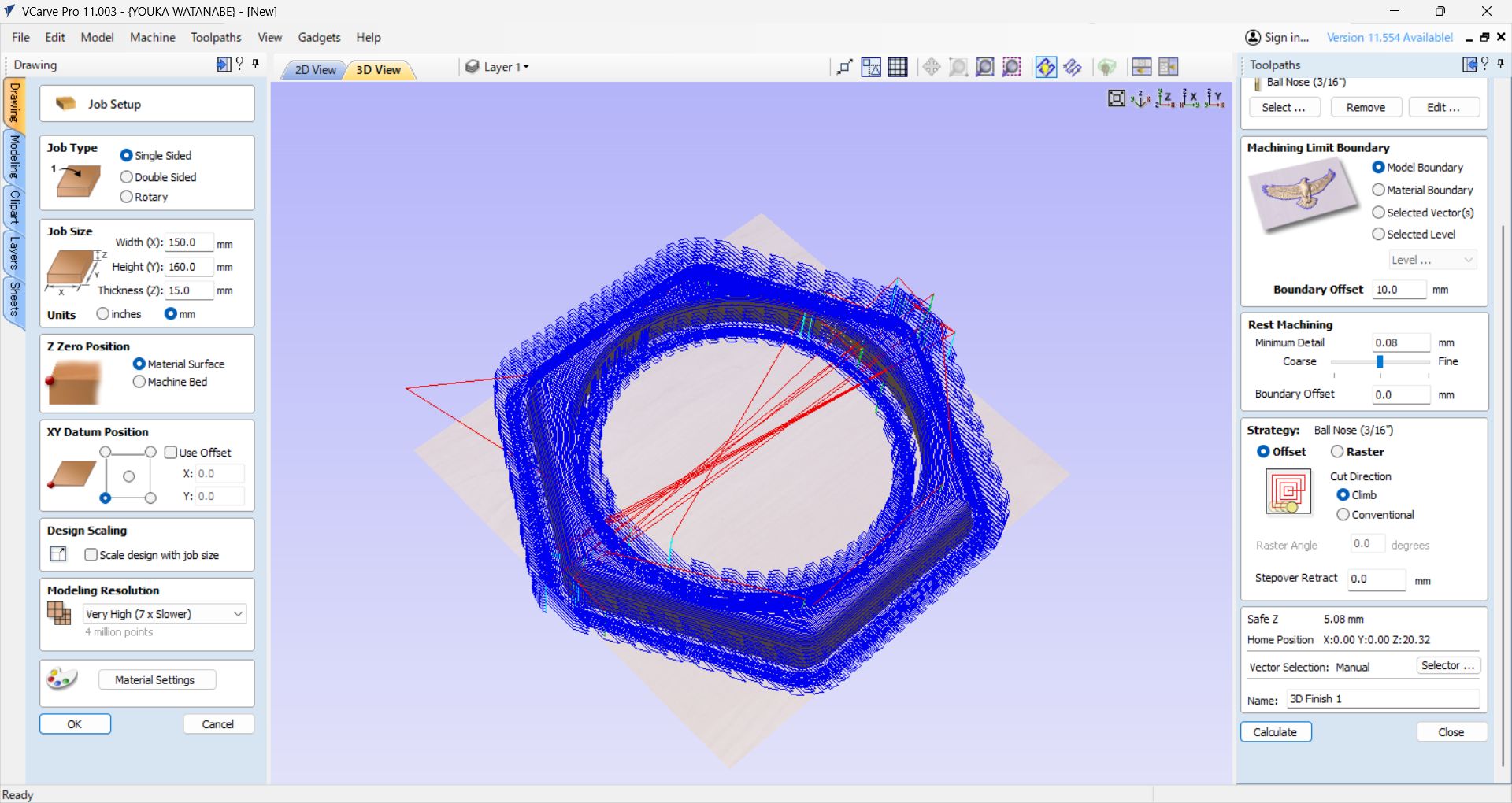
At first, when I set the Model Boundary, an error occurred when generating toolpaths.
The error was resolved by using Material Boundary, but Material Boundary has many
milling parts, which is wasteful and time-consuming.
As a solution, I set a Boundary Offset of the tool width (∔α) in the Model Boundary and
was able to cut successfully.
CNC
As with Machining, the following steps are used in OpenBuild for cutting.
After RoughCut is finished, it is necessary to replace the tool for Finishing.
The XY axis is not changed, but only the Z axis is reset (as in SRM). It is necessary
to set z-axis correctly (see below) since it cause CNC may or may not cut out the
wood.
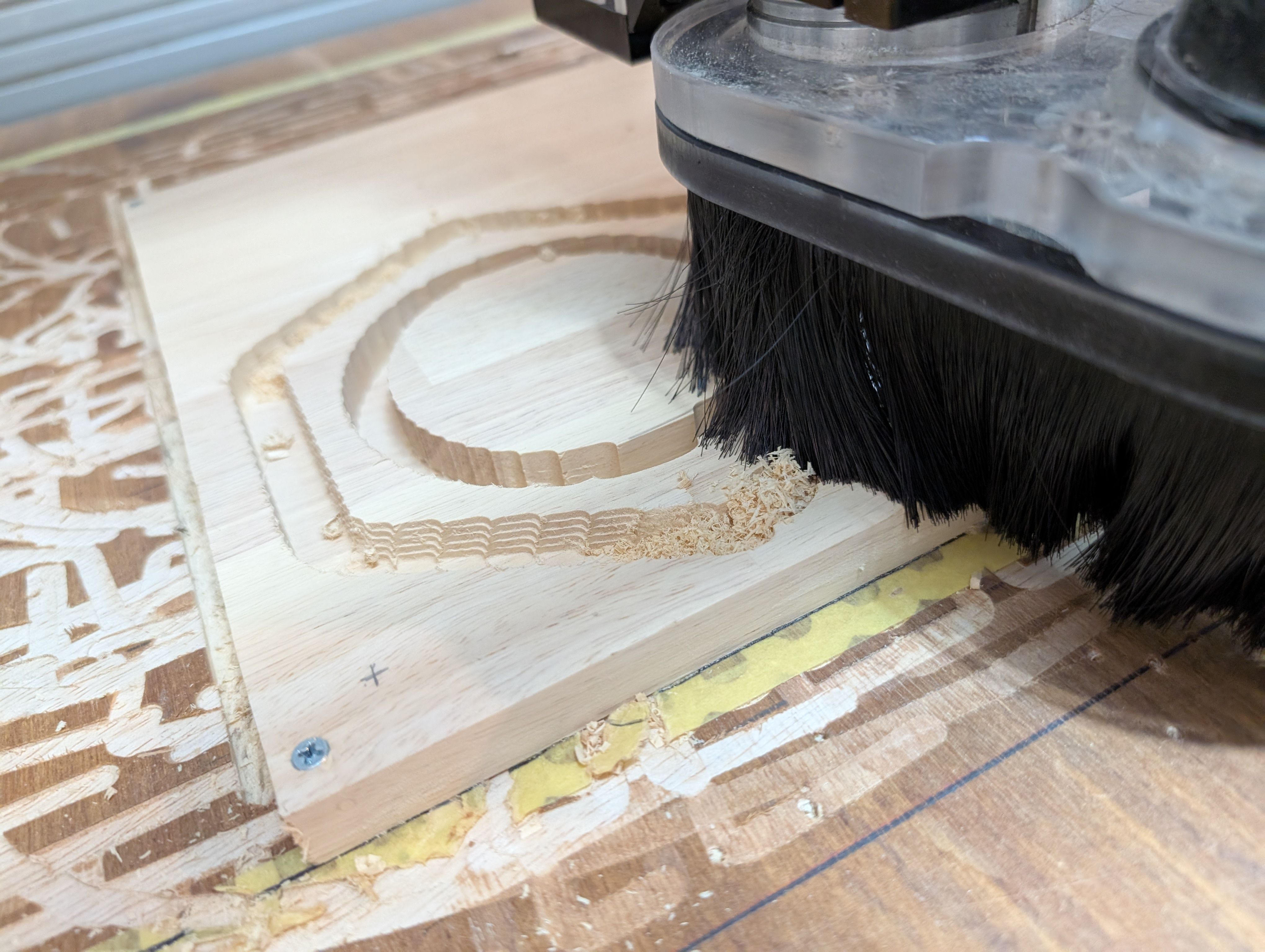
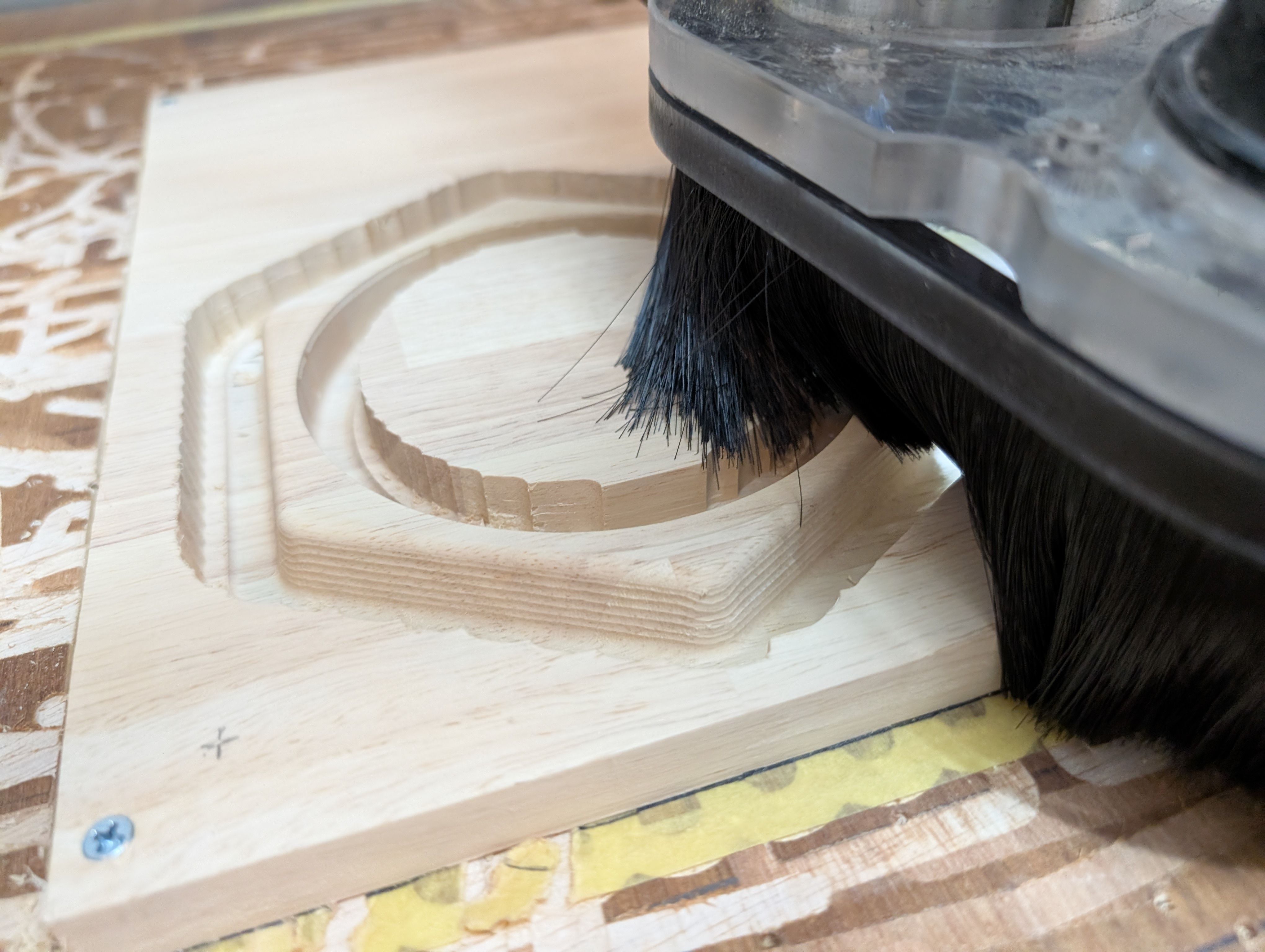
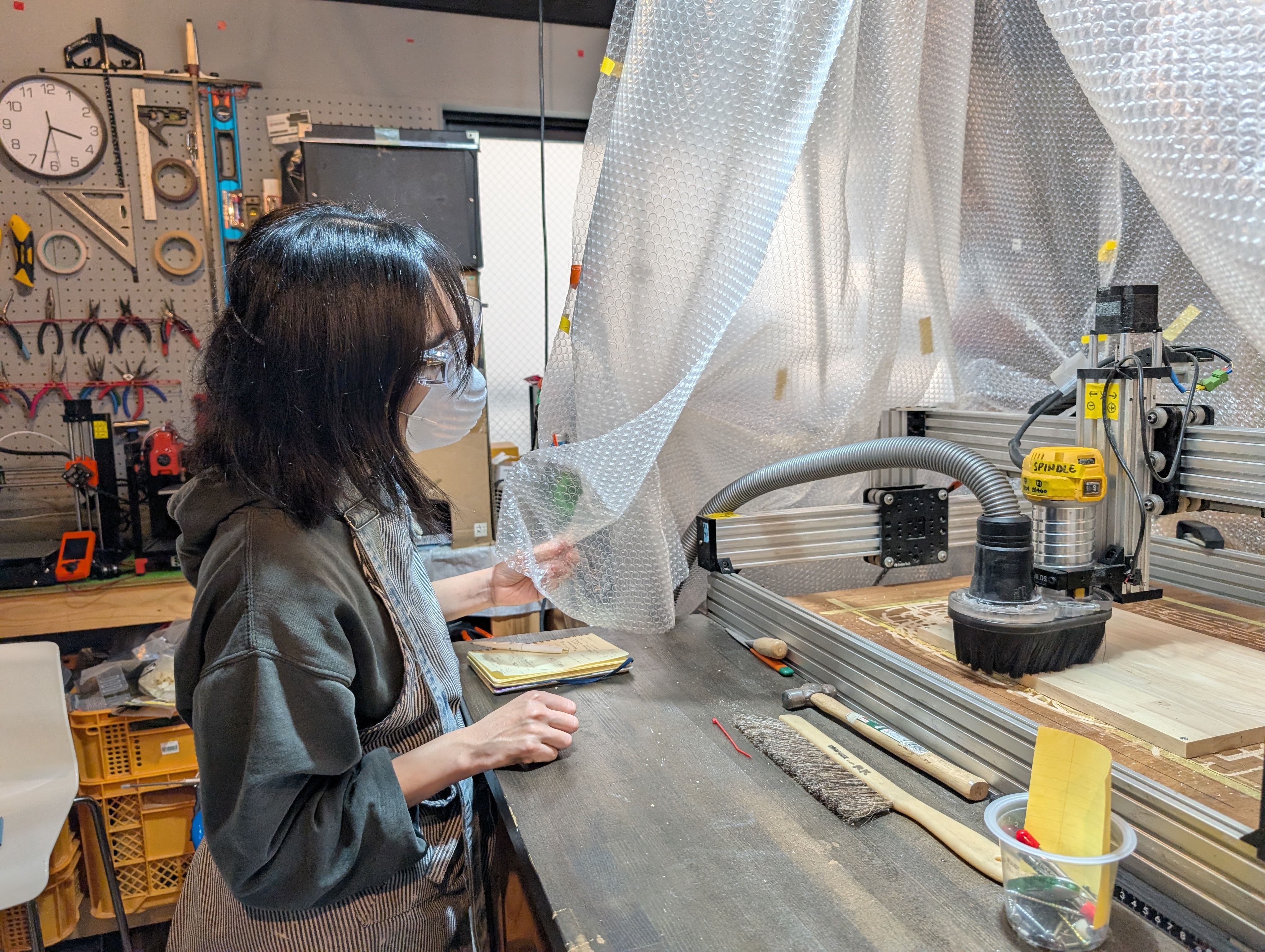
Safety (Protect Eyes and wear mask)
In some cases, it is necessary to fix the part to be cut with screws.
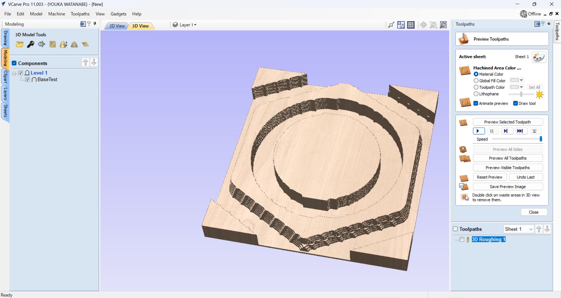
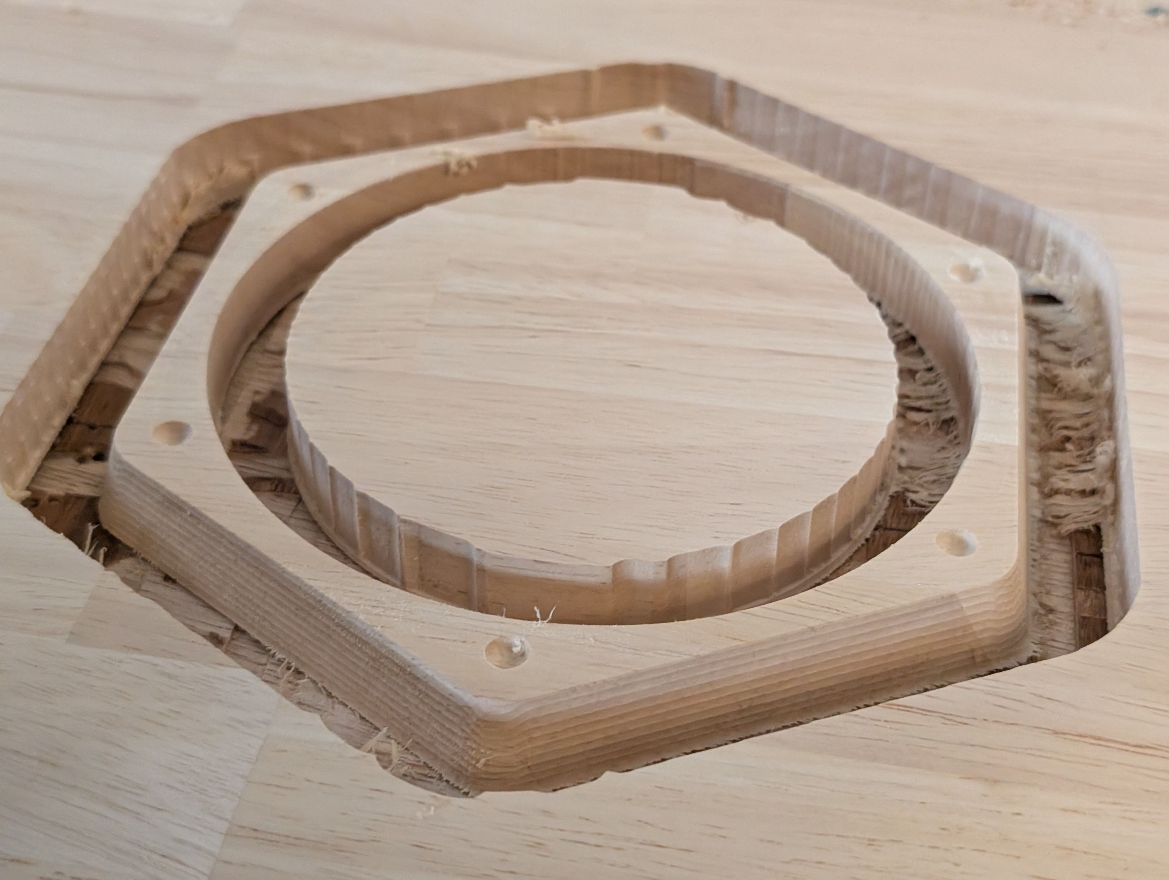
Finishing
Requirement: Smooth Finishing
At the time of scraping, the surface was generally finished smooth.
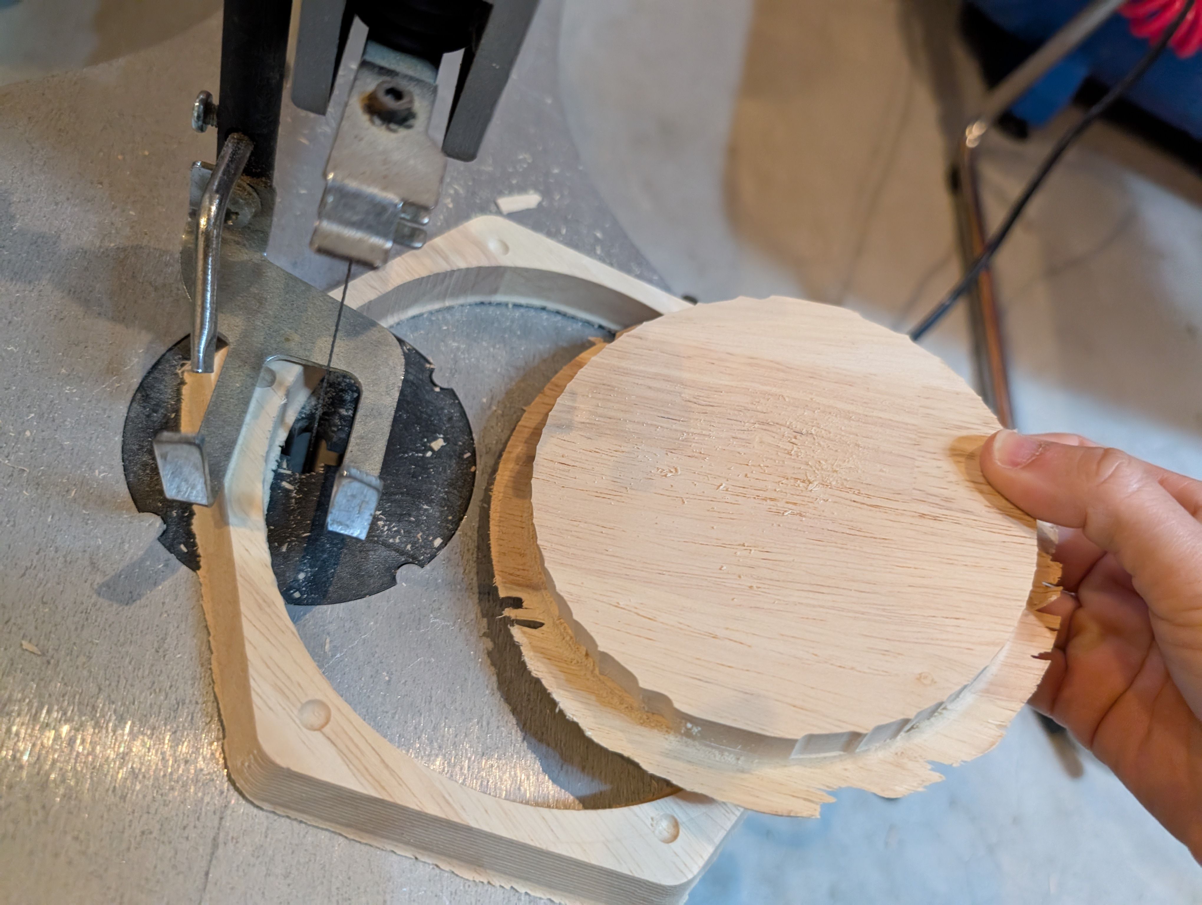
However, some of the bottom surface remained and was not separated from the wood,
resulting in a process of cutting and sanding the remaining parts with a thread saw.
(If the Z-axis is not set correctly, it may or may not be able to be cut.)
Result of assembly
References
https://docs.vectric.com/docs/V12.0/Aspire/JPN/Help/form/Orientate
3D Model Flat/index.html
https://www.autodesk.com/jp/support/technical/article/caas/sfdcarticles/sfdcarticles/JPN/Unable-to-open-a-file-after-crash-in-Fusion-360.html
https://www.autodesk.com/jp/support/technical/article/caas/sfdcarticles/sfdcarticles/JPN/Converting-Fusion-360-to-DWG-or-DXF.html
https://www.vectric.com/support/tutorials/vcarve-pro/?playlist=getting-started-with-vectric-software&video=how-to-import-and-machine-a-3d-model
https://www.youtube.com/watch?v=cORavE0W3fo
Extra: Other processes that have been implemented and are not part of the current assignment
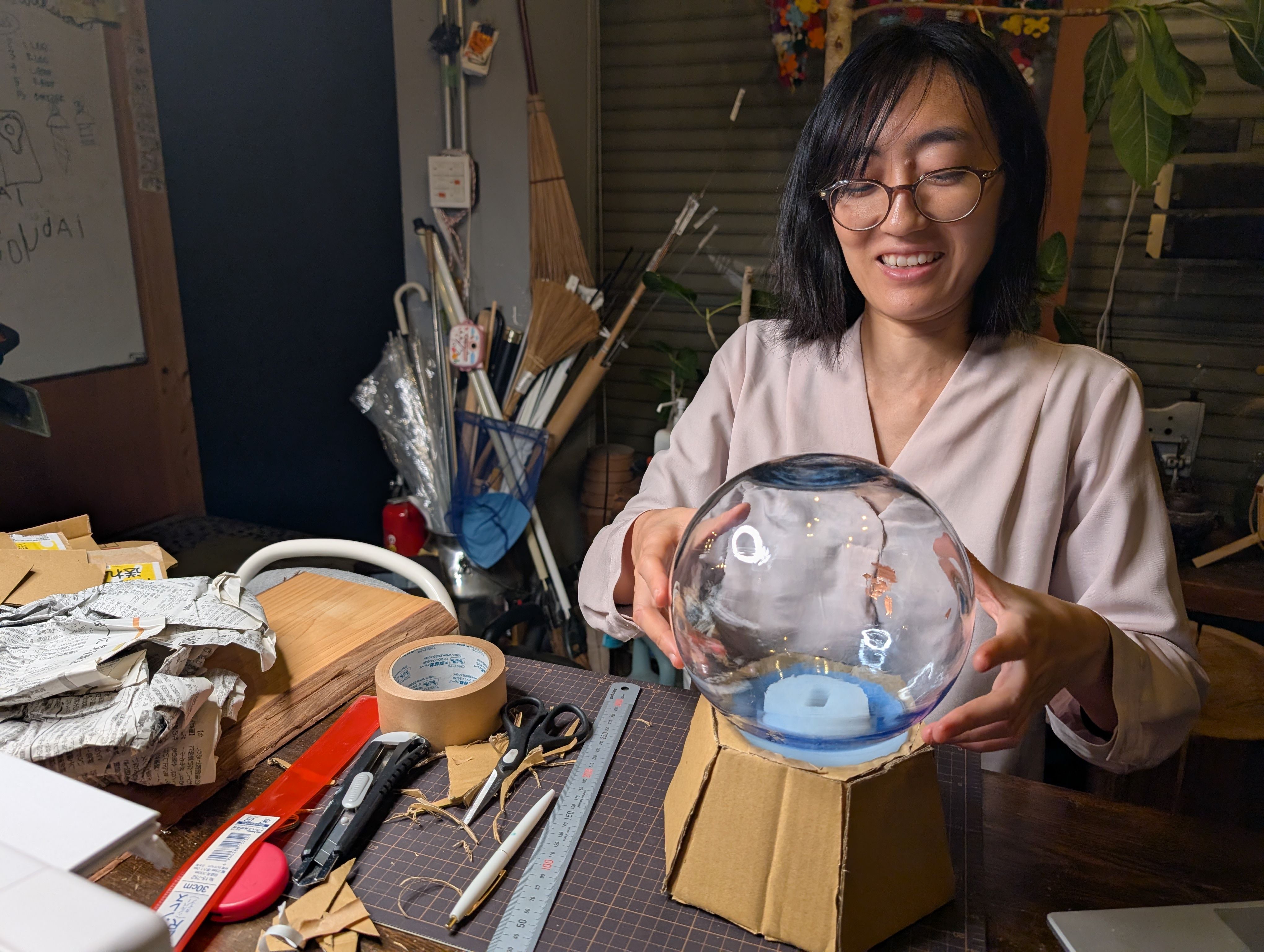
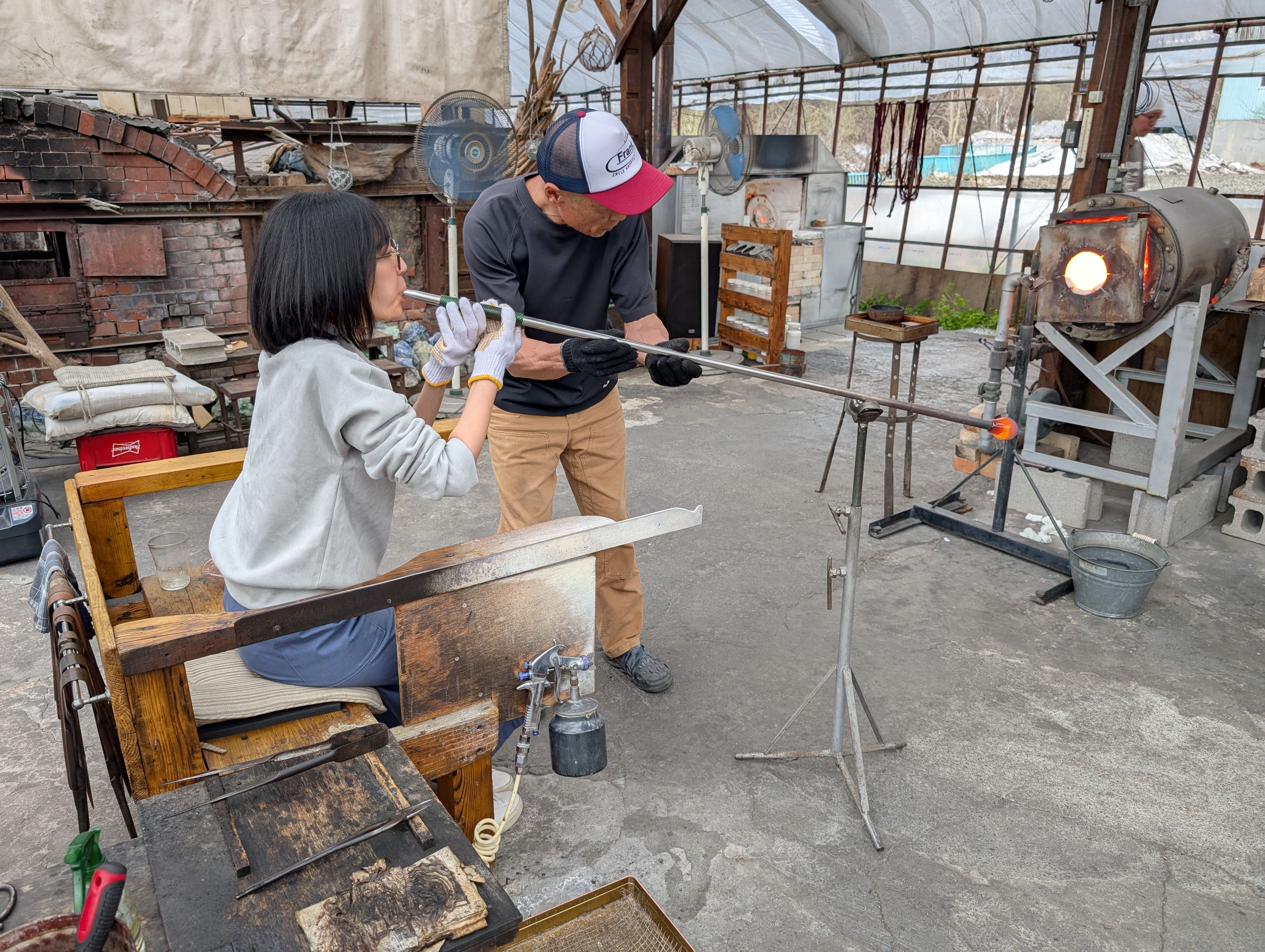
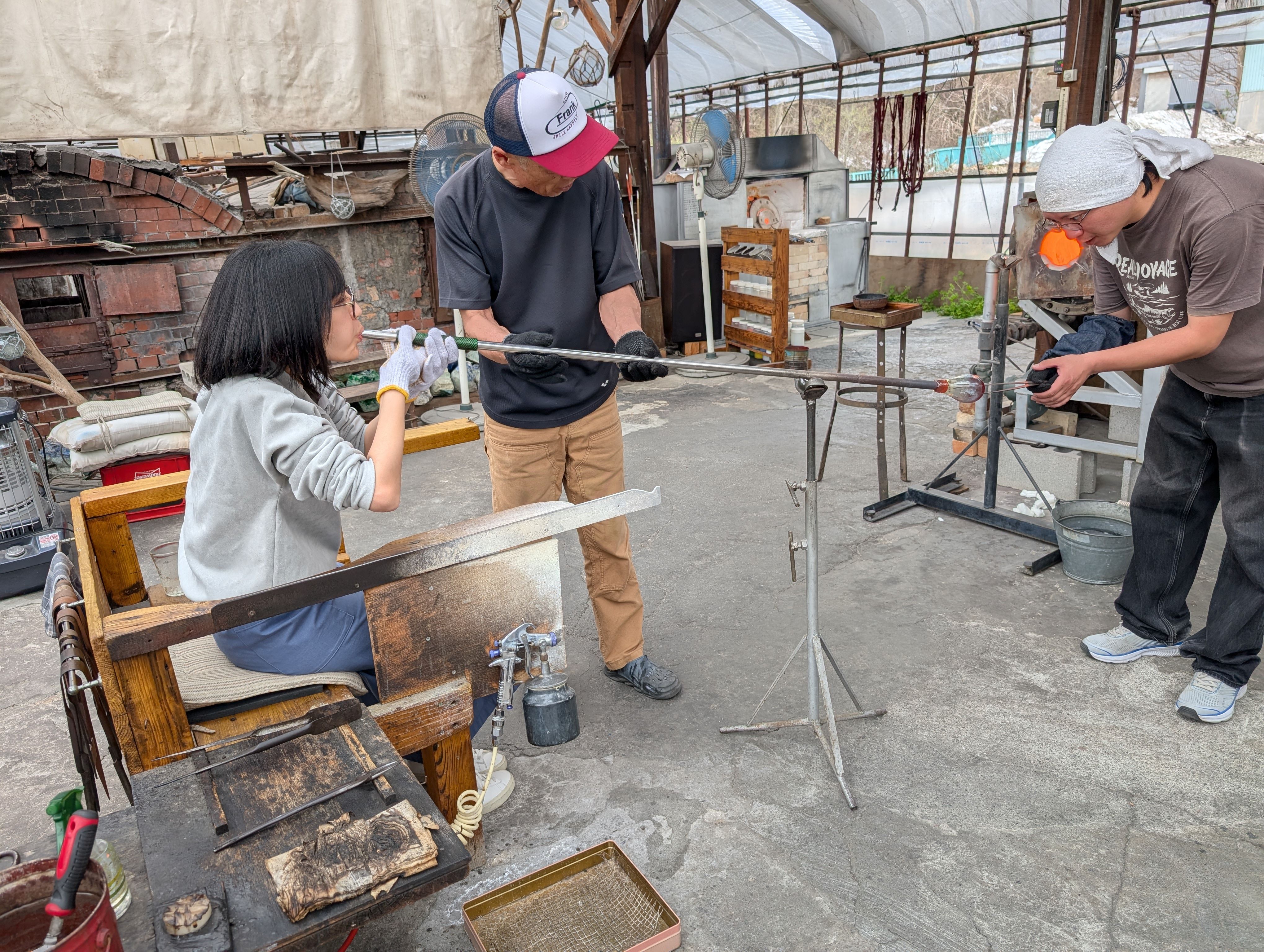
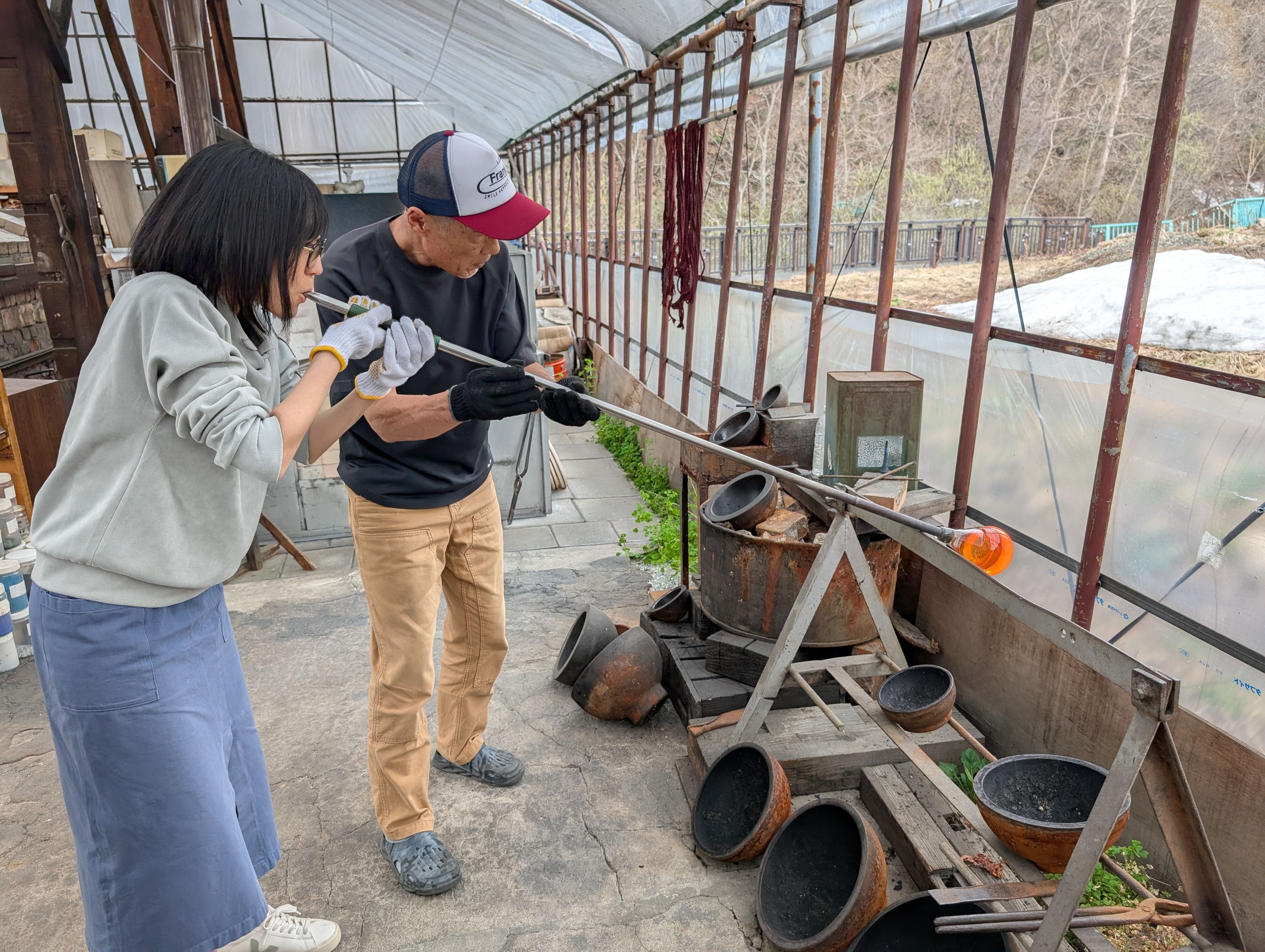
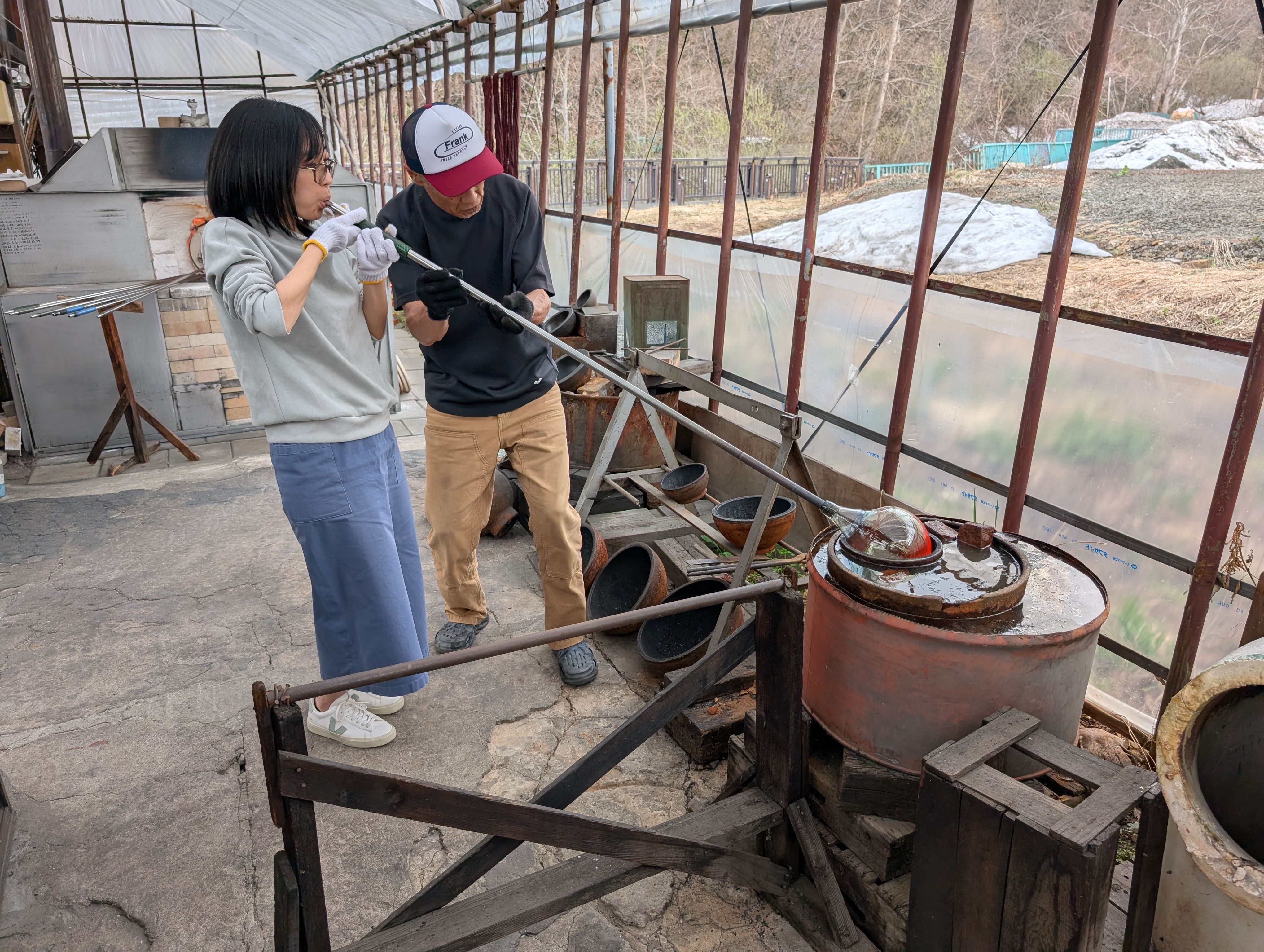
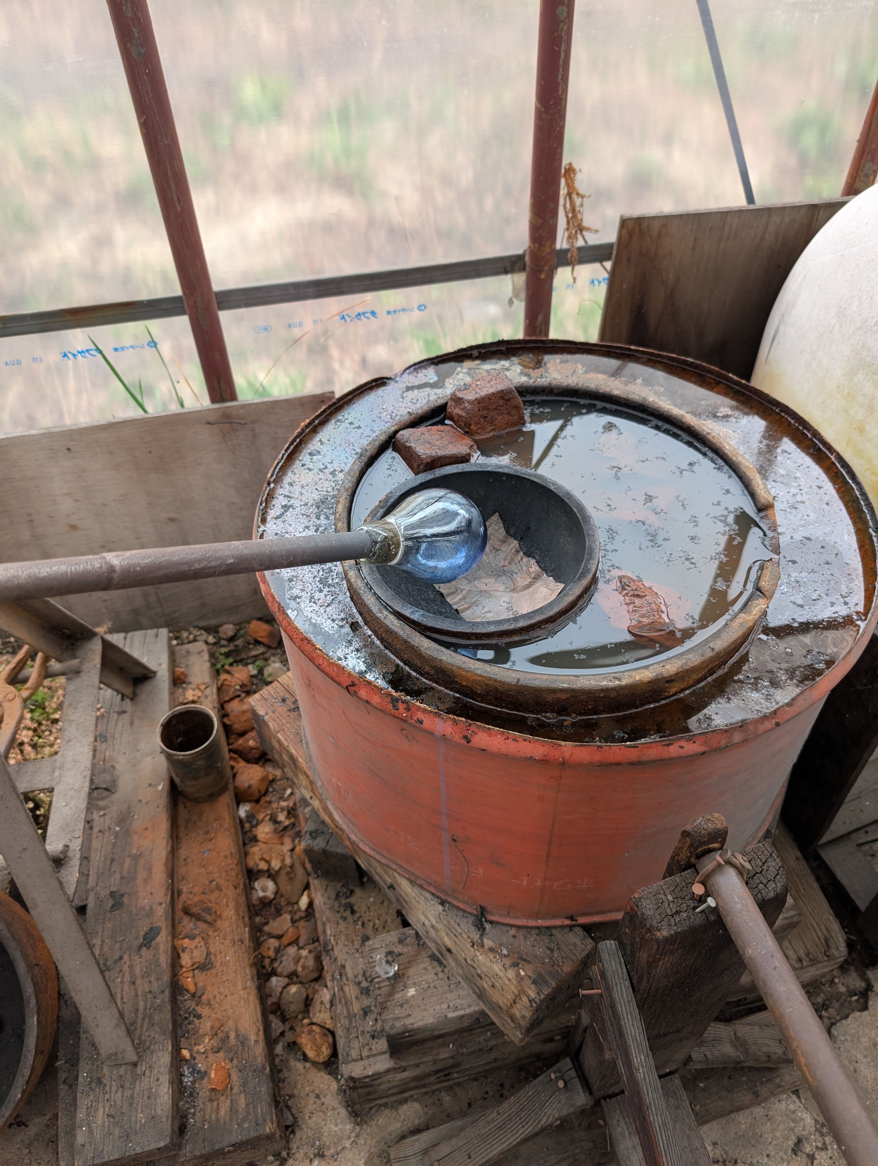
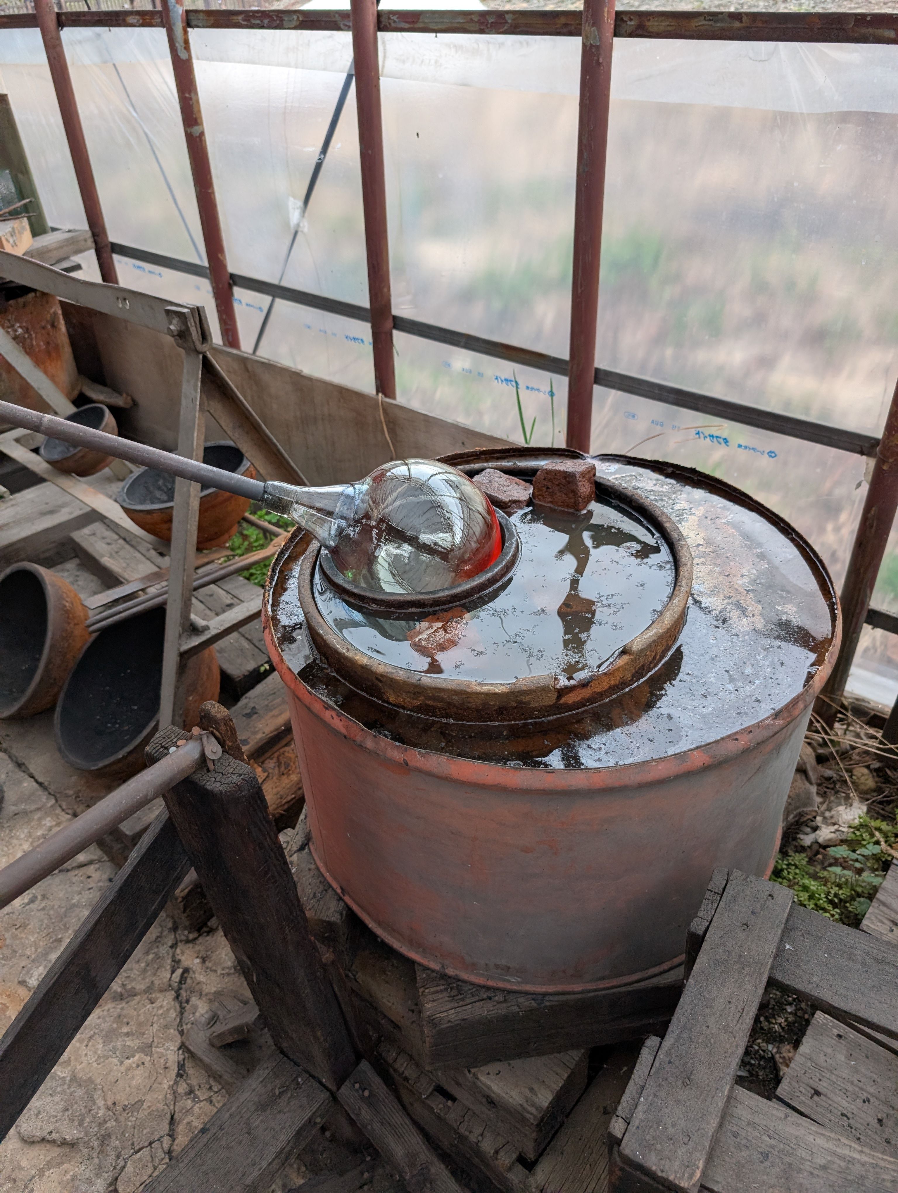
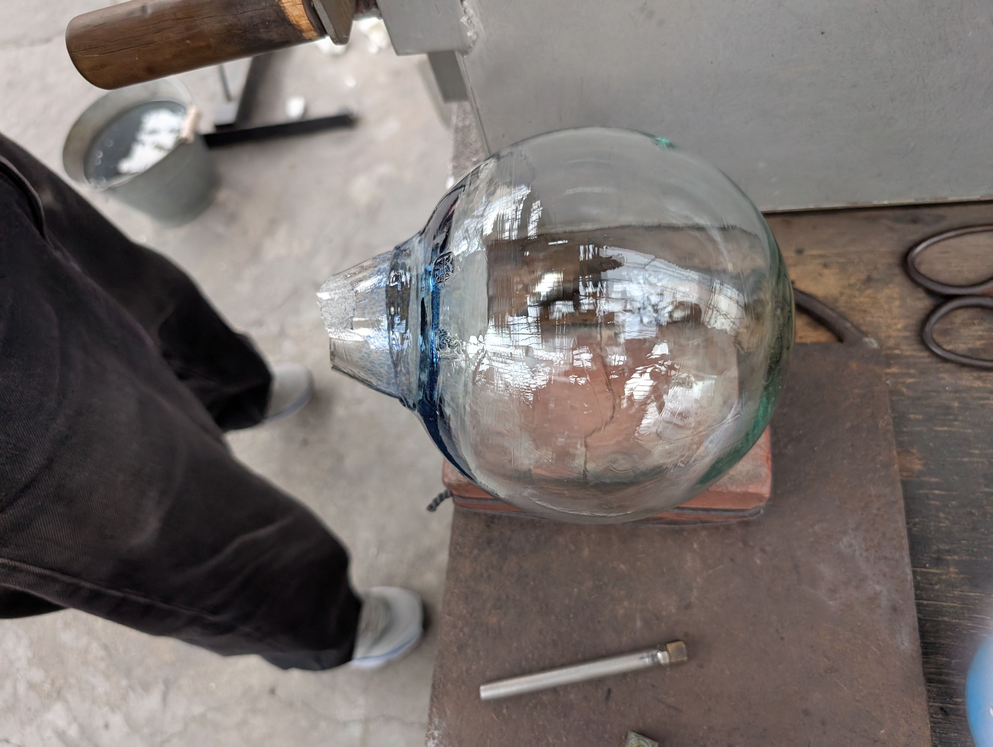
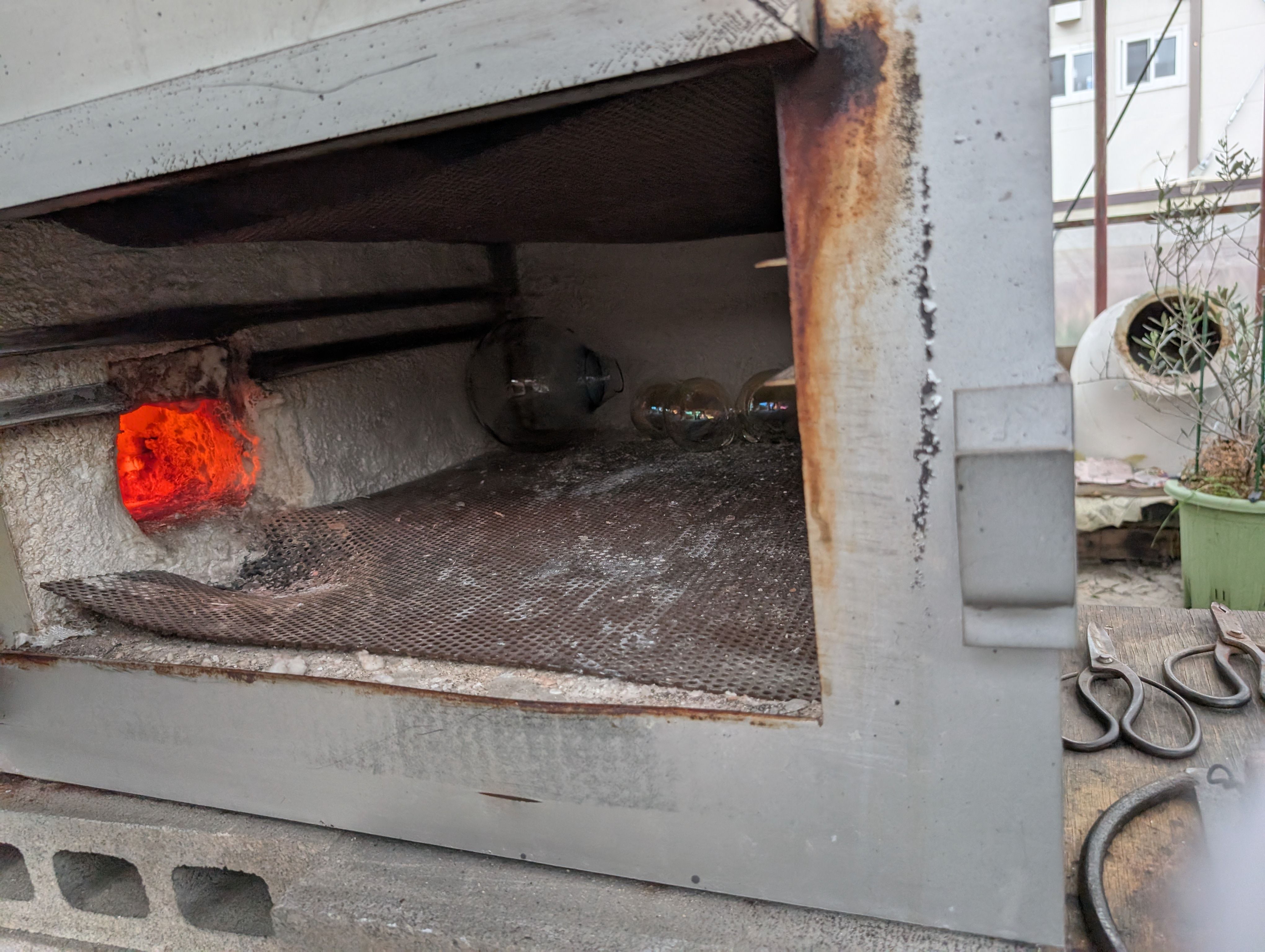
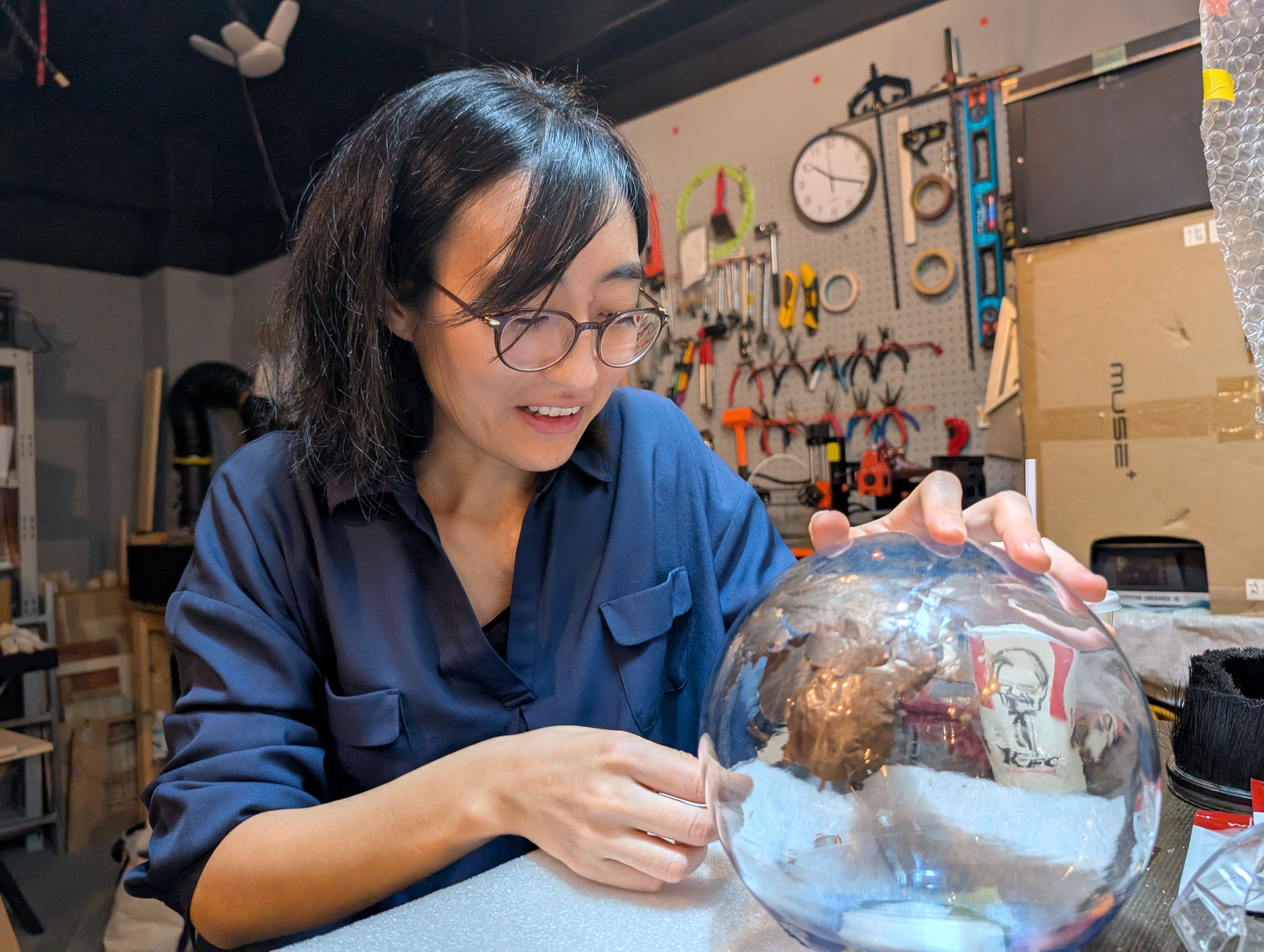
Glassblowing
(Visit to a floating ball production studio in Hokkaido, Japan)
The ball is rotated on a mold and breathed into the mold.
In this case, an existing mold was used for the sphere, but various shapes are possible
by creating a digital mold.
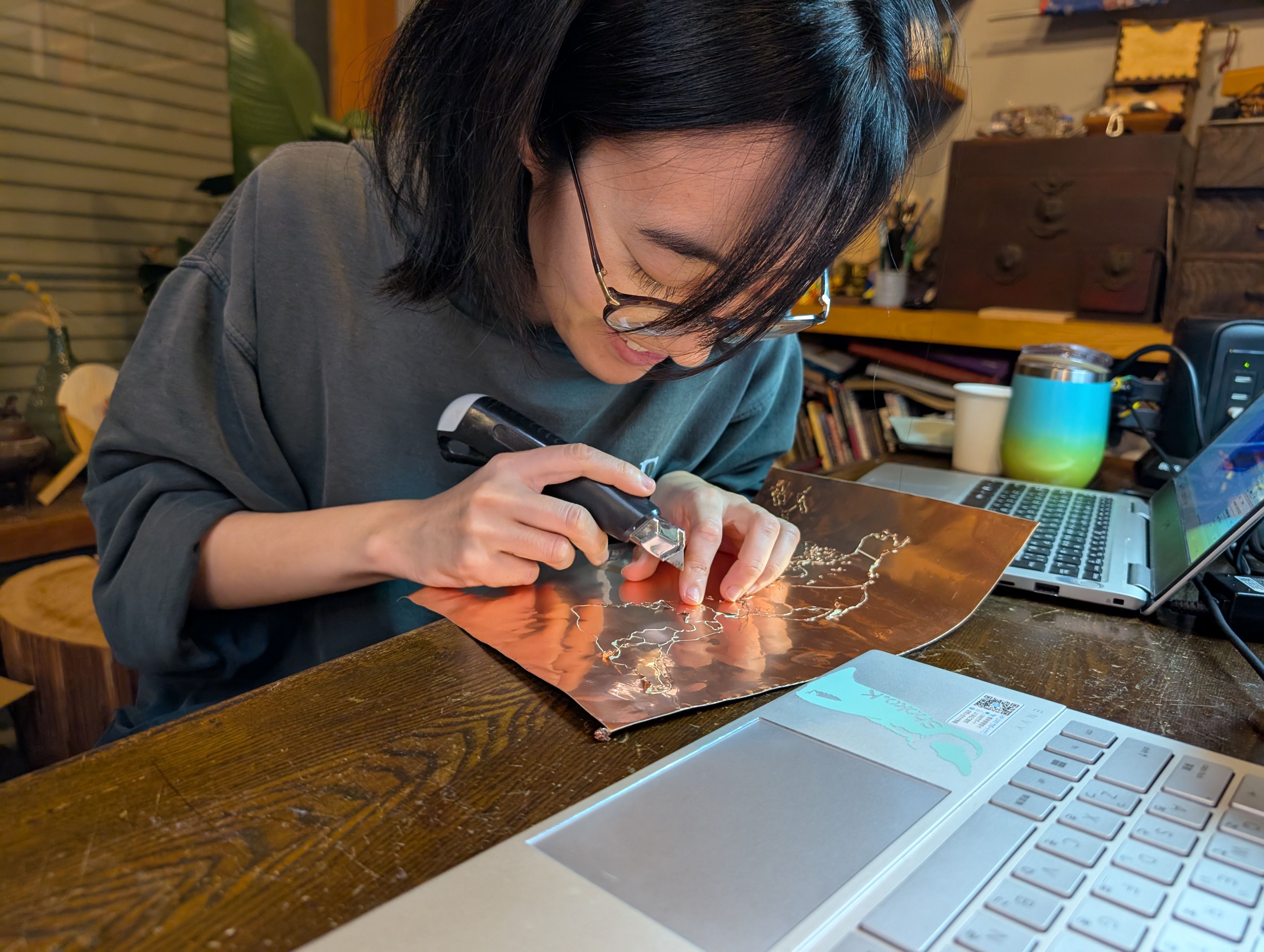
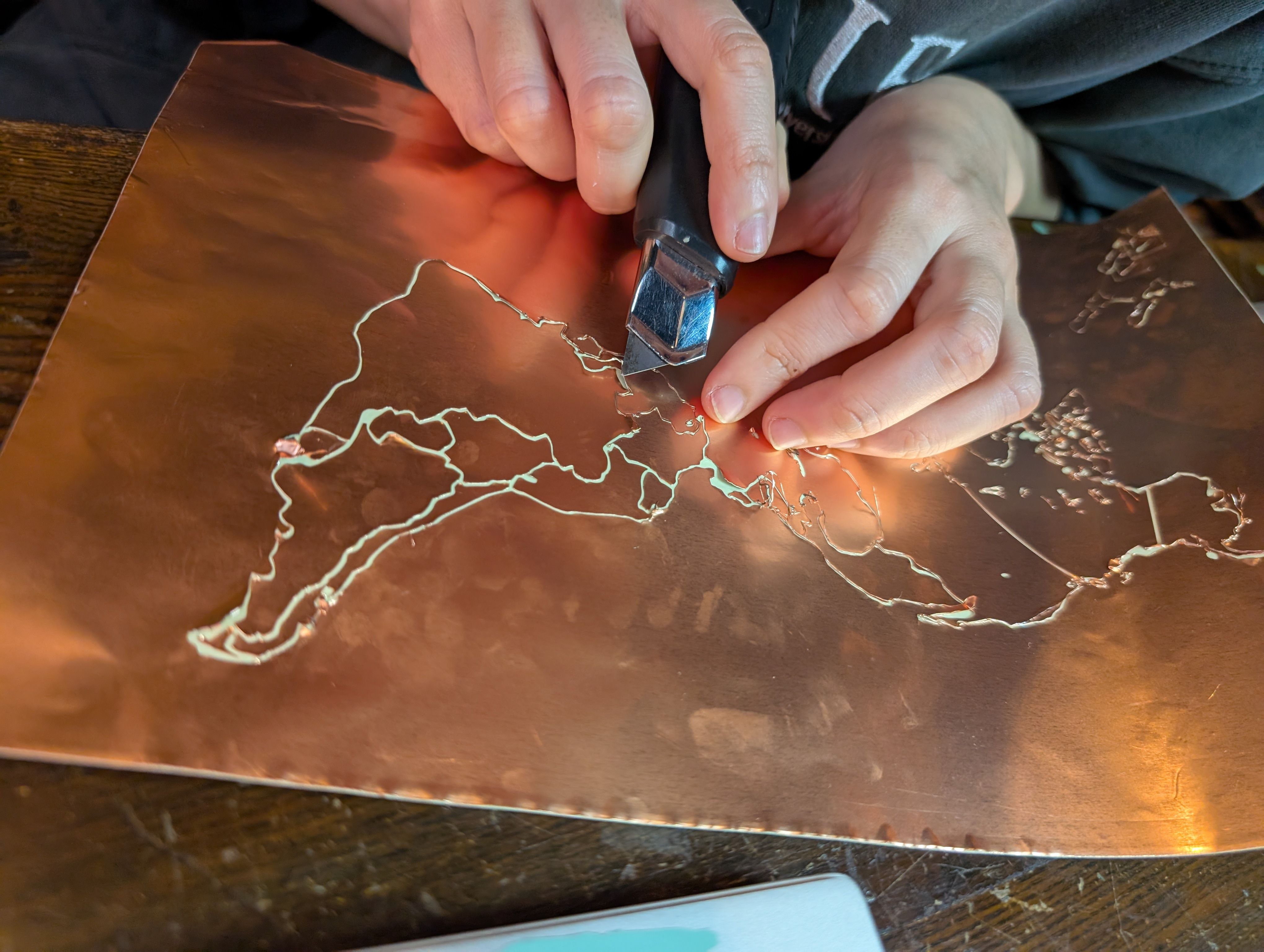
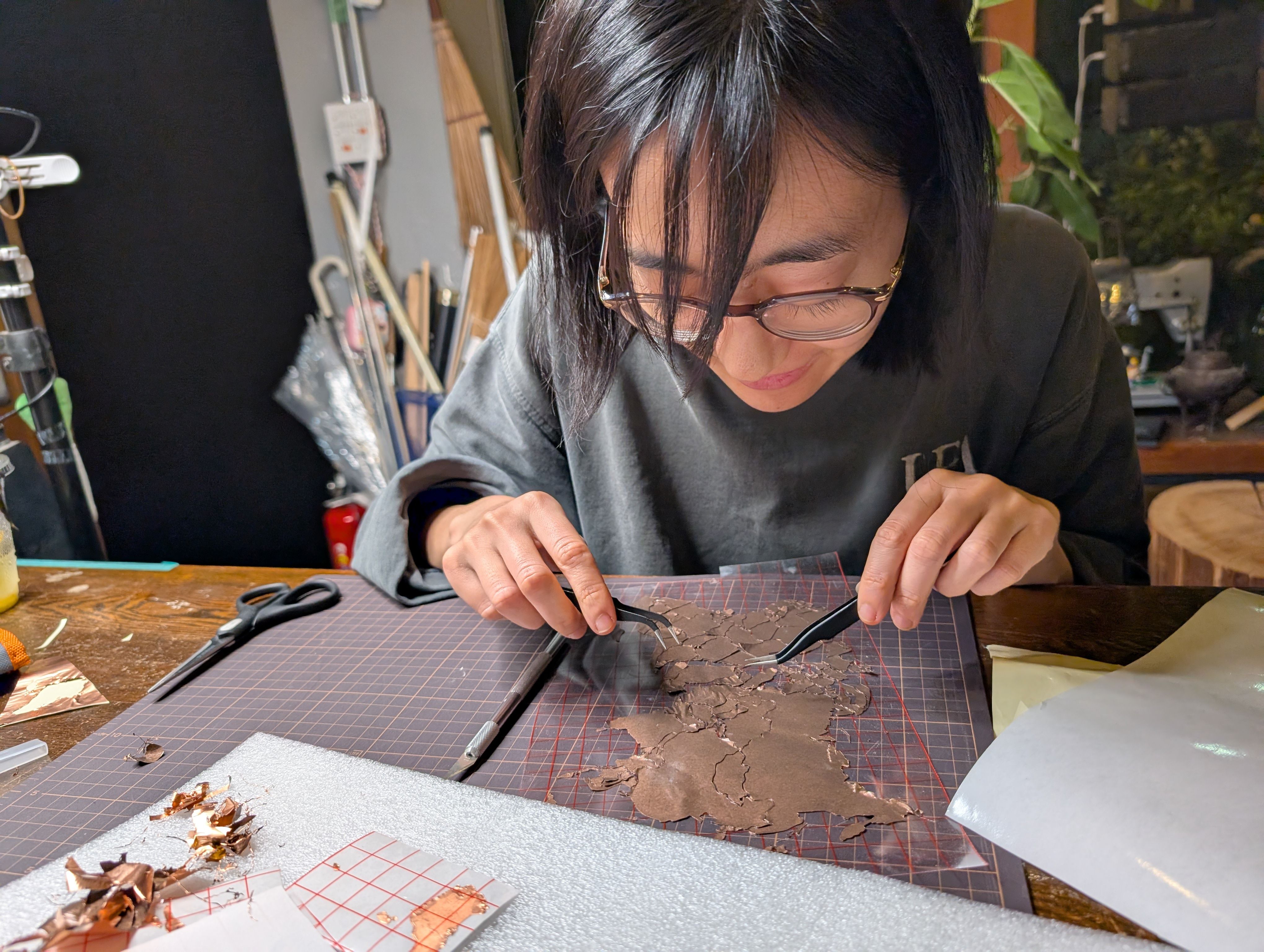
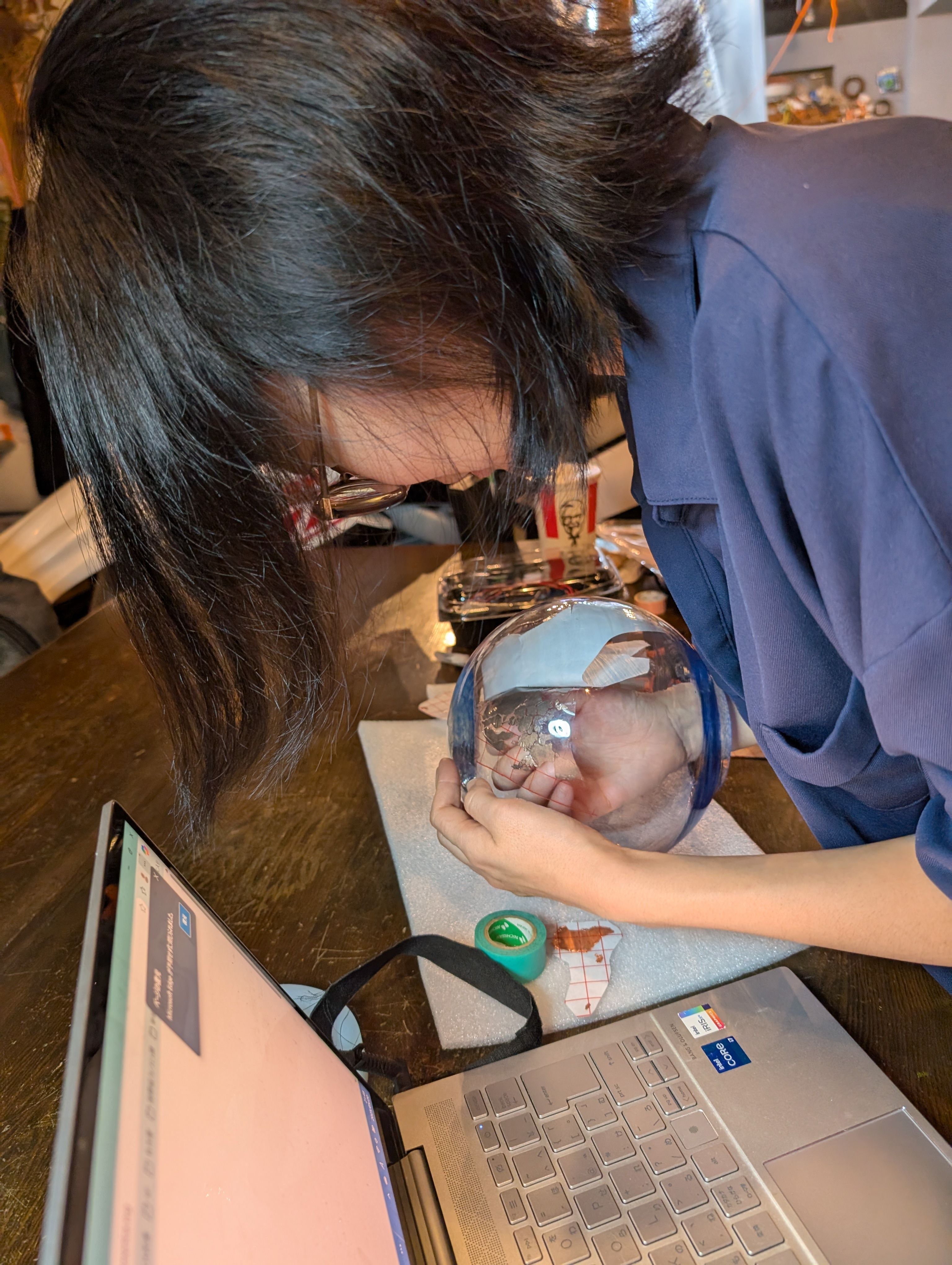
Copper Sheet Vinyl Cut
Copper sheet is cut into the shape of a country. Fixed to the inner surface of the
glass.
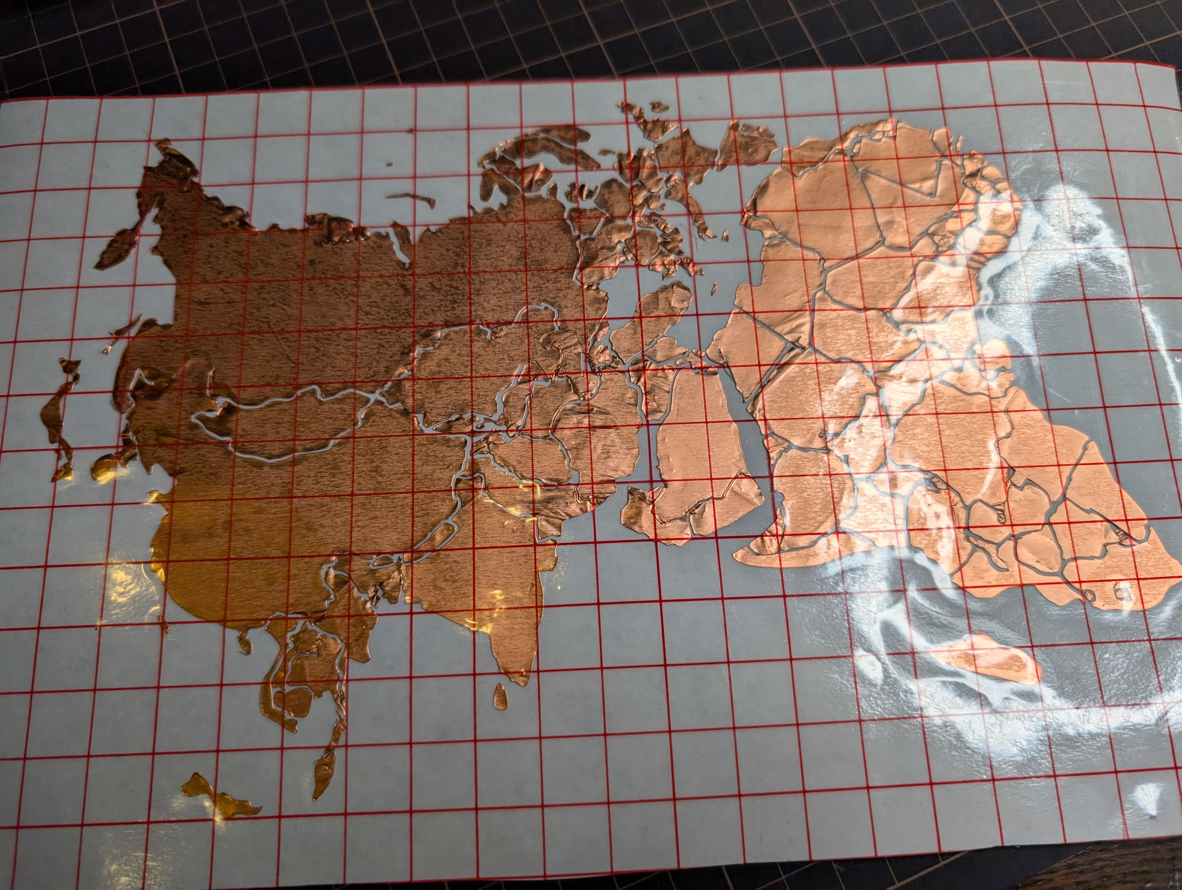
I wanted to map the globe while maintaining the relative positions of the countries, so
I searched for a map projection that would suit this.
I used the map data from Wikipedia and adjusted in size with Inkscape:
File:Blank_world_map_Dymaxion_projection.svg
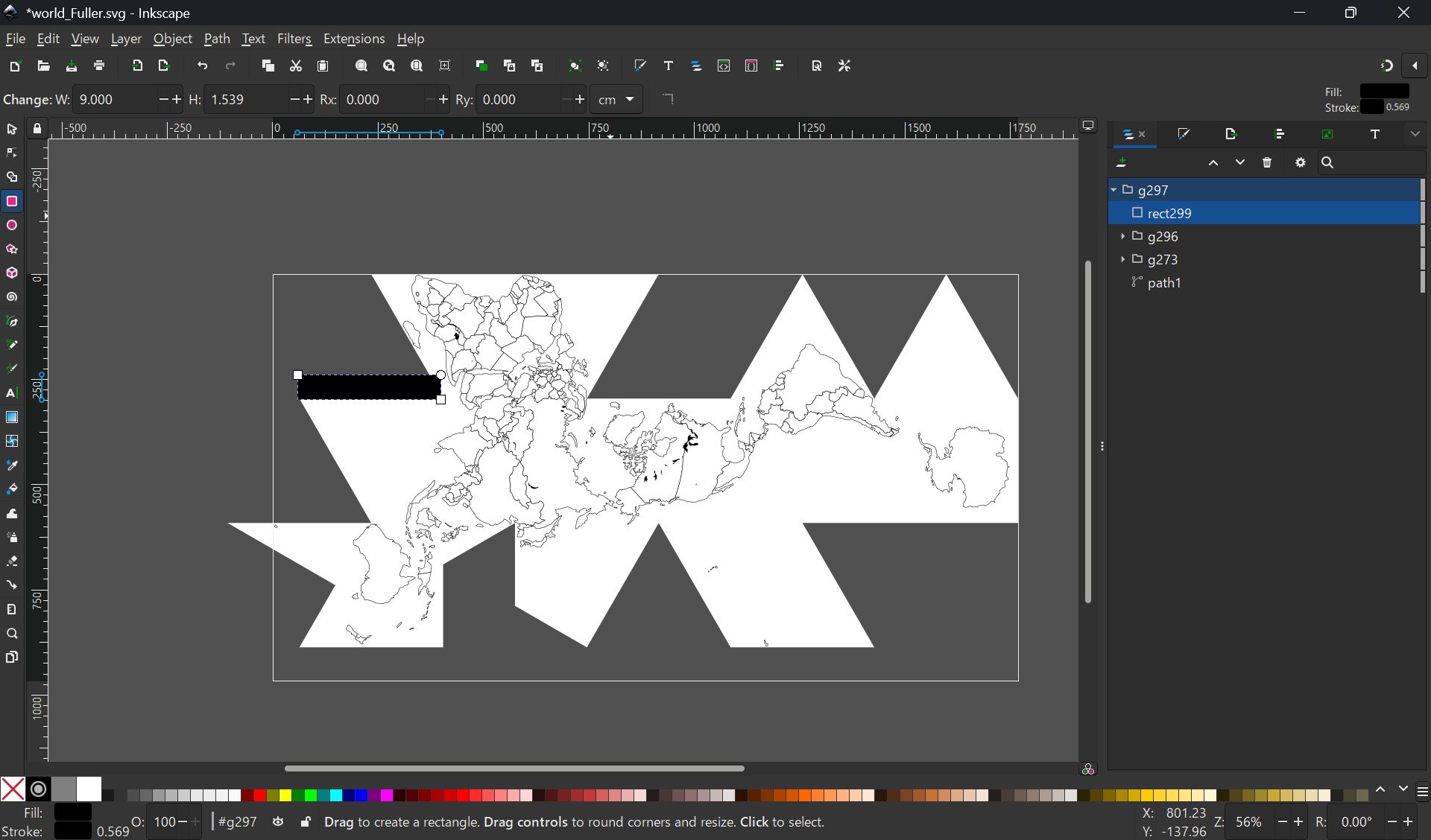
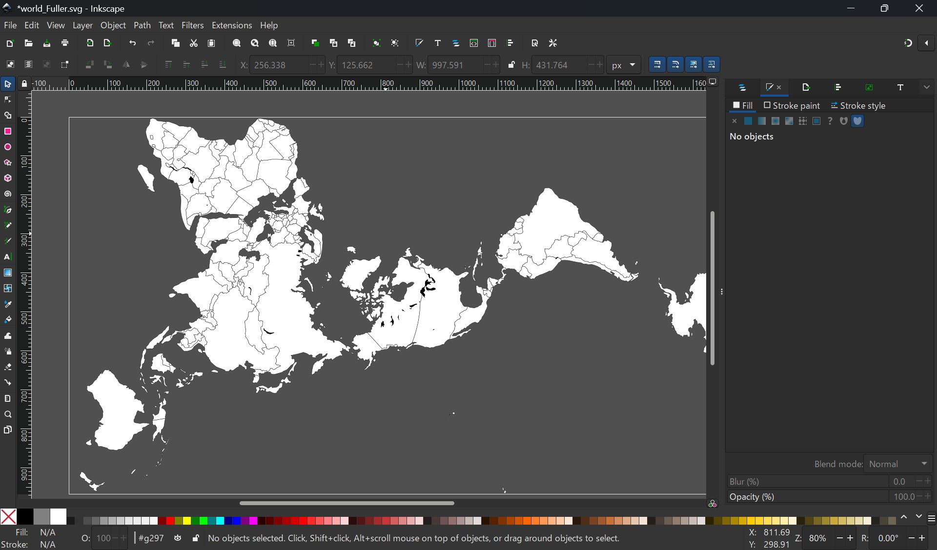
Export the map symmetrically with PNG (to be pasted from the inside of the sphere)
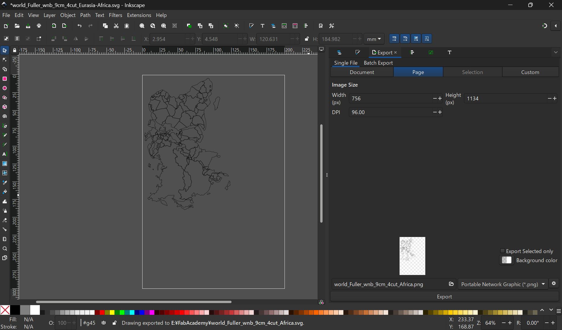
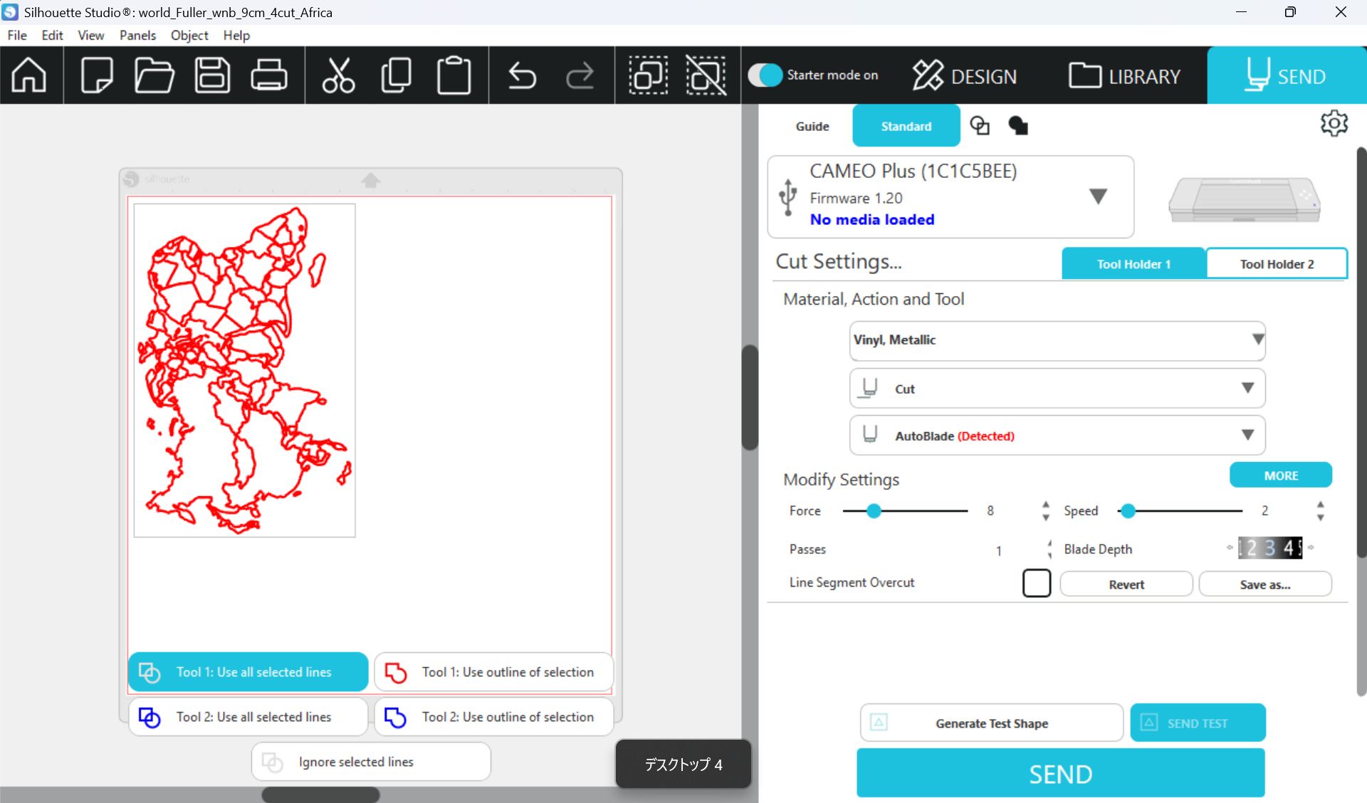
Used Silhouette Studio
Setting
Force: 8, Speed:2, Passes:1, Bade Depth: 5
*If the pressure or depth is too strong, the copper will float up, so it is important
to use the right amount of Force and Depth.
Point
- How to fix the copper foil on the inner surface of the spherical glass. At first, I tried to fix the copper foil on the glass using an application sheet while maintaining the exact position of the countries, but it was difficult to fix the sheet on the glass, especially on the long horizontal Eurasian continent, and the sheet kept coming off. Since the fixation was weak, spray glue was used.
- Connection of copper wire from MCU6(soldering) Since it was difficult to solder inside the sphere, solder was fixed separately in the form of copper foil tape. It was successfully fixed in a country with a large area, but it was difficult to keep it fixed in a country too small.
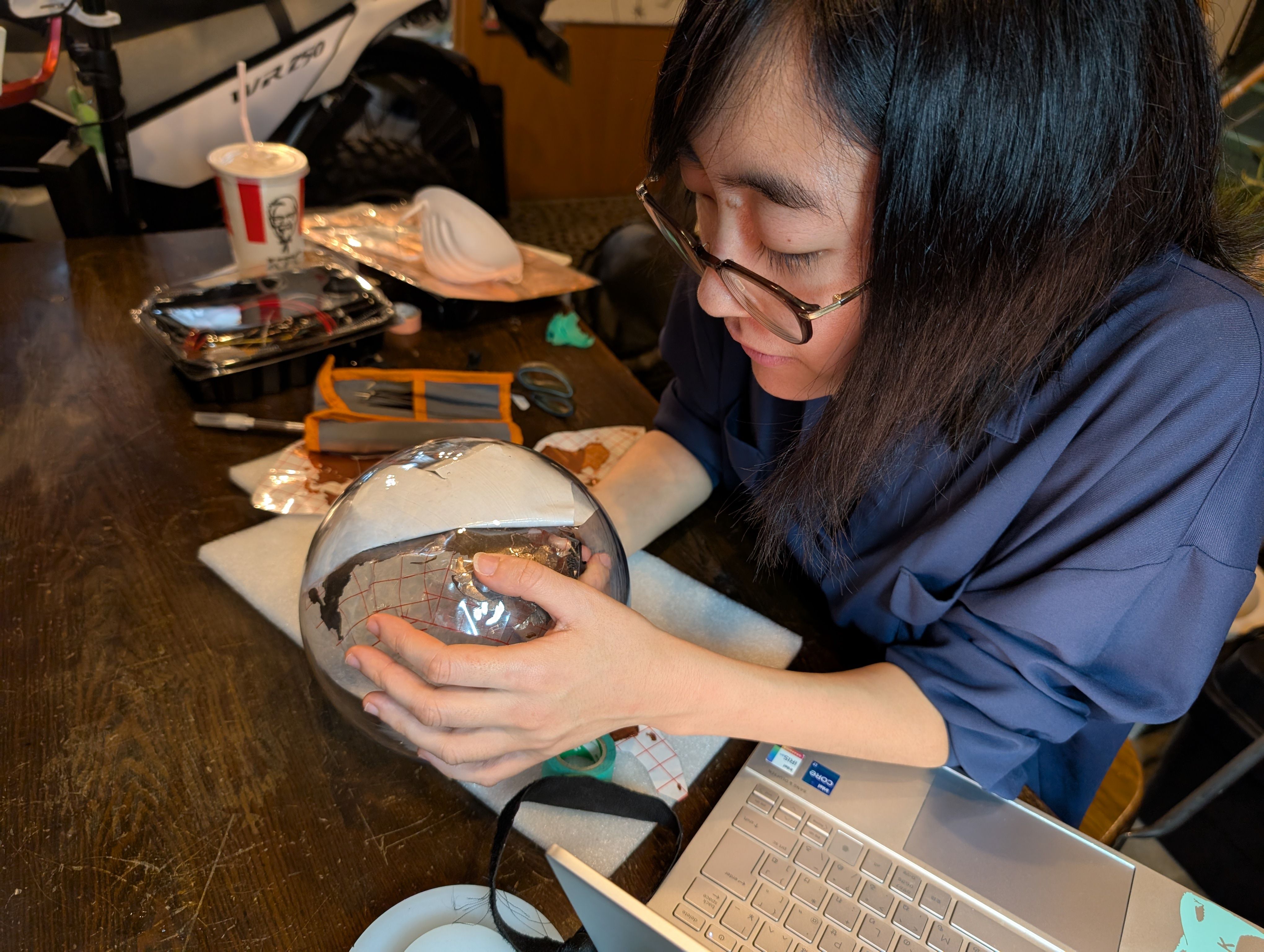
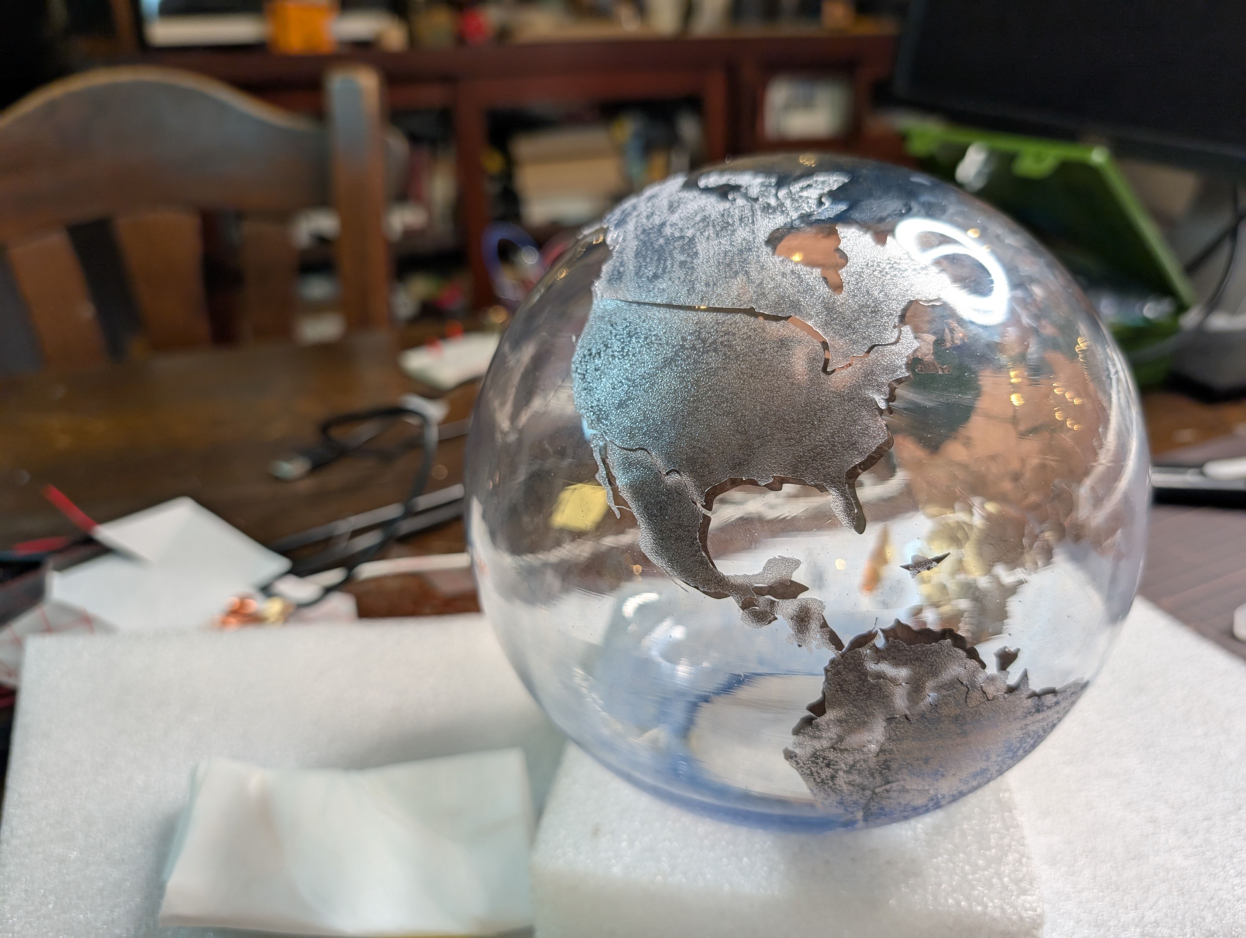
I also put a frosted glass-like sheet on the outside.
Outcomes
- crv files for VCarve
- tap files for OpenBuild
- ai file for side support parts Laser cut
- svg file for world map vinyl cut
I could try wood milling and found setting for tool path