#15 System Integration
This week I considered how to integrate the whole project.
Assignment
- Design and document the system integration for your final project
Outcomes
What did I do this week:
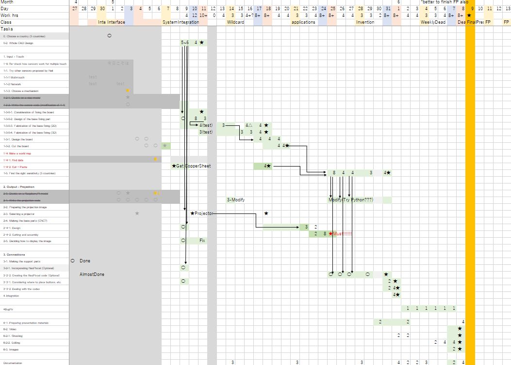
- Revise schedule till June
- Design whole CAD model for my Final Project
- Assemble and check the wiring
- *New things I tried this week
1.Revise schedule till June
I made schedule during Midterm, and I revised it this time. My target date is June 9th.
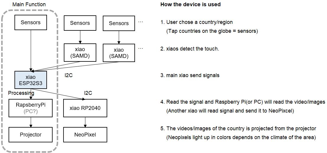
Also, this is the system diagram.
For first spiral, basically I'll focus on Main Function.
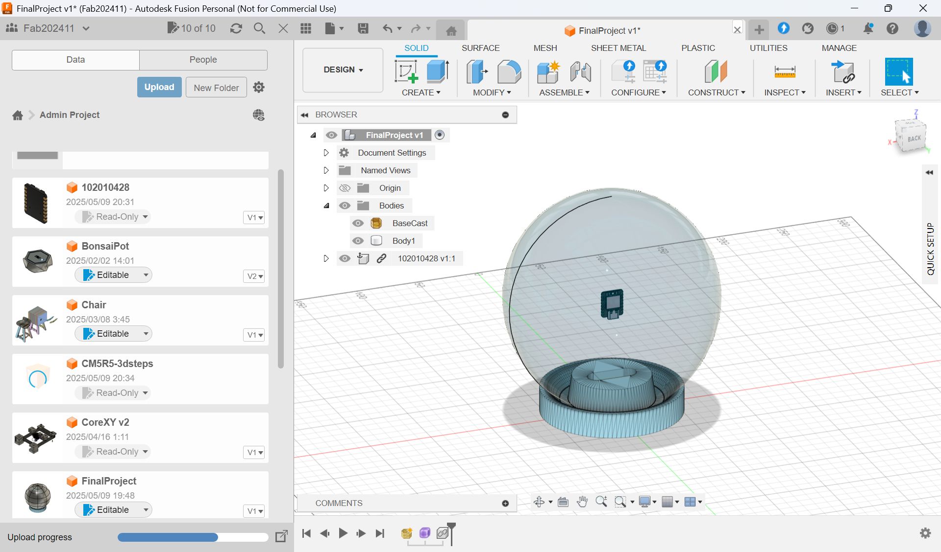
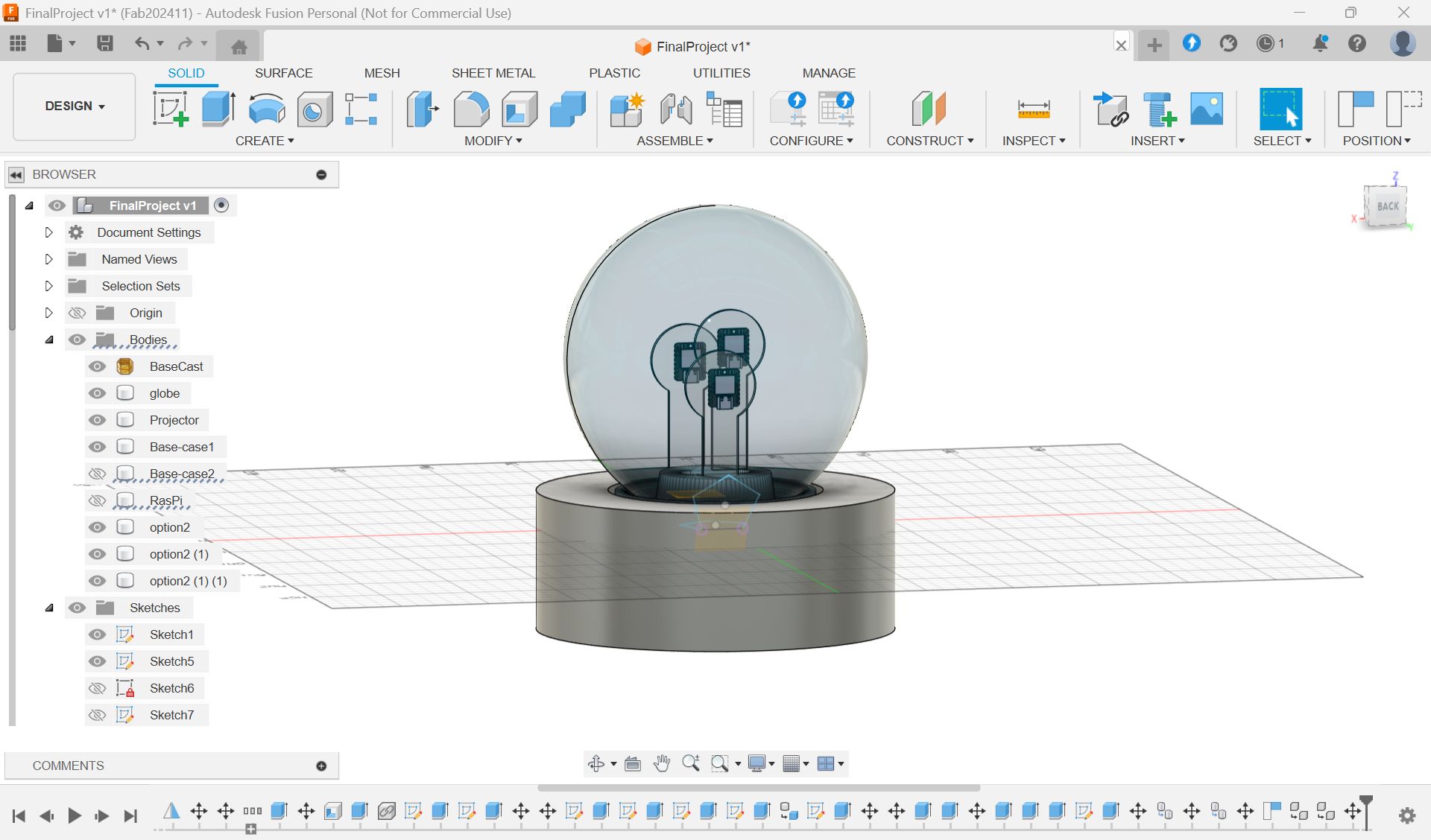
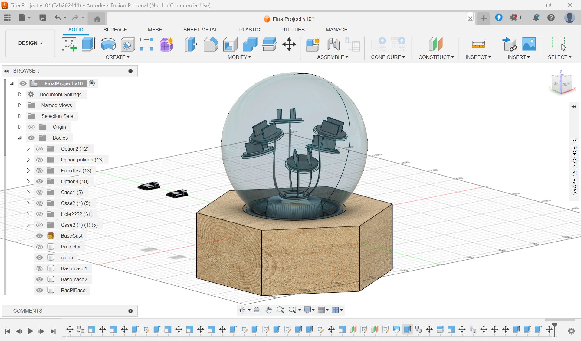
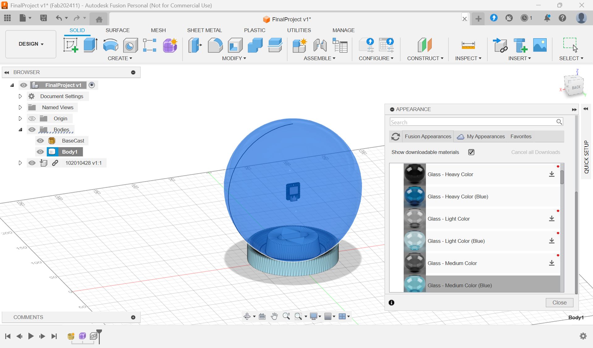
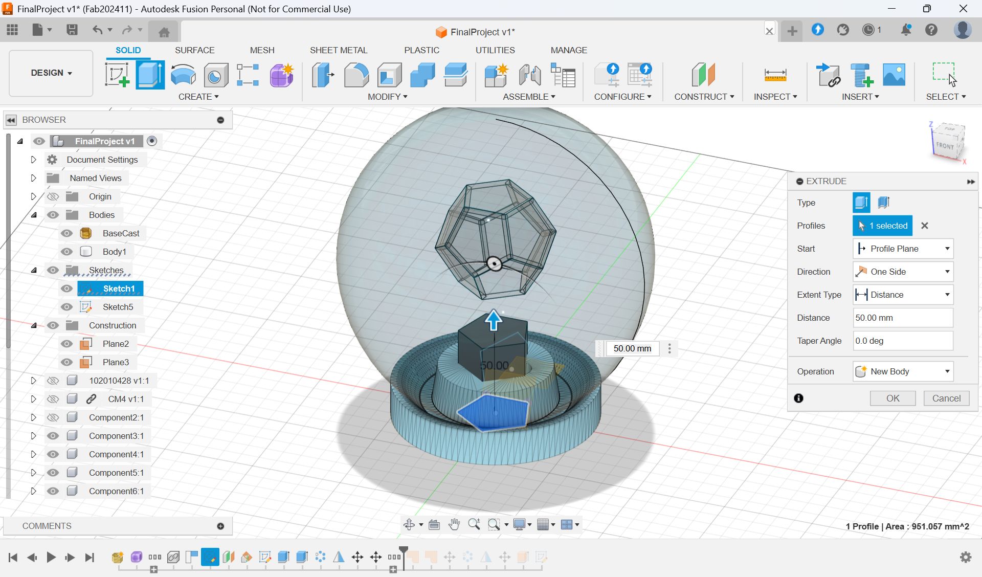
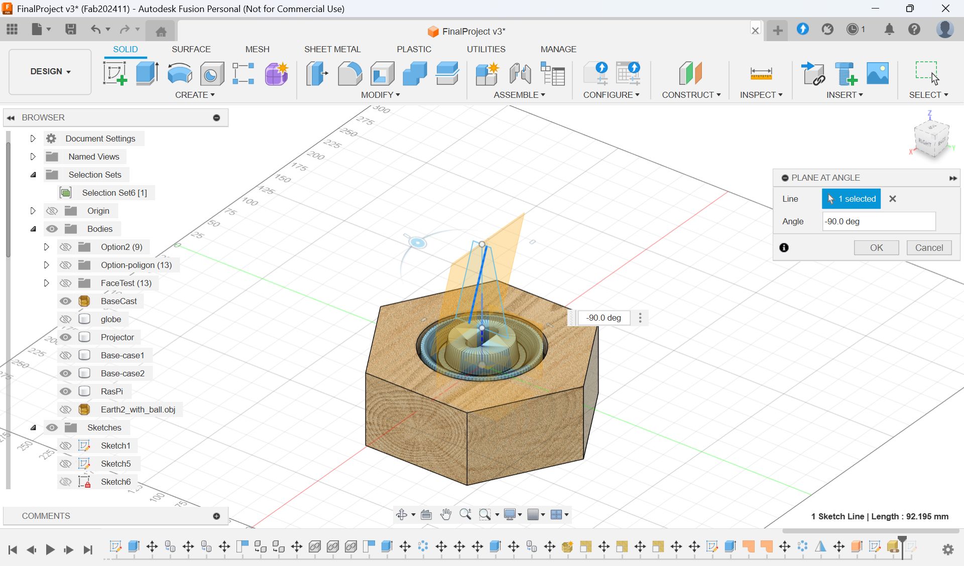
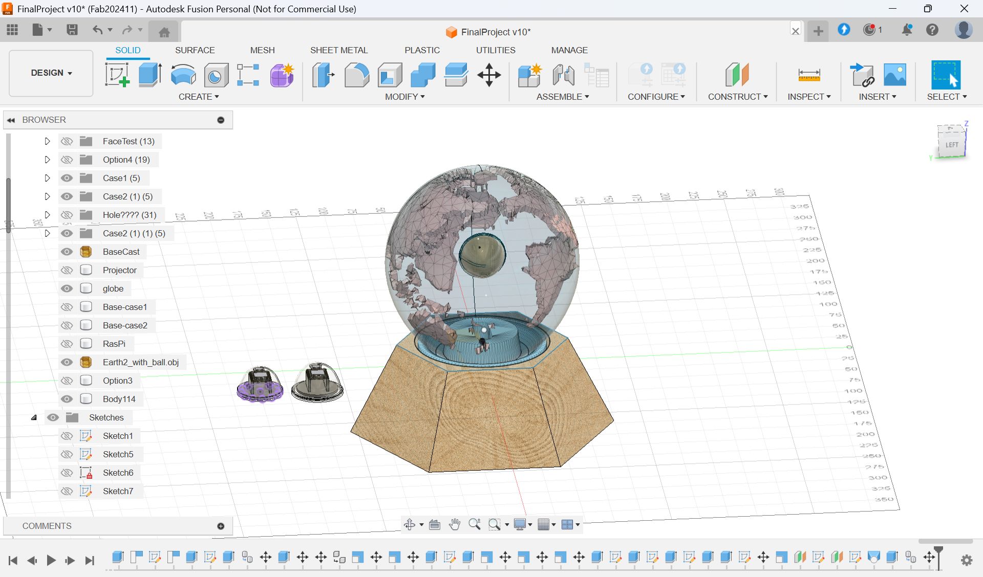
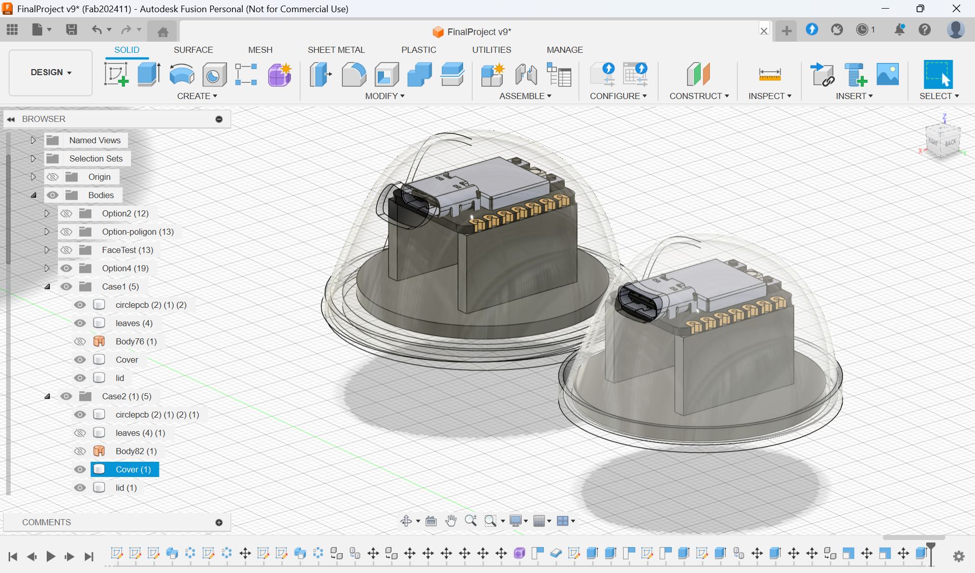
2.Design whole CAD model for my Final Project
I haven’t made a CAD model, so I made it to consider/clarify whole design.
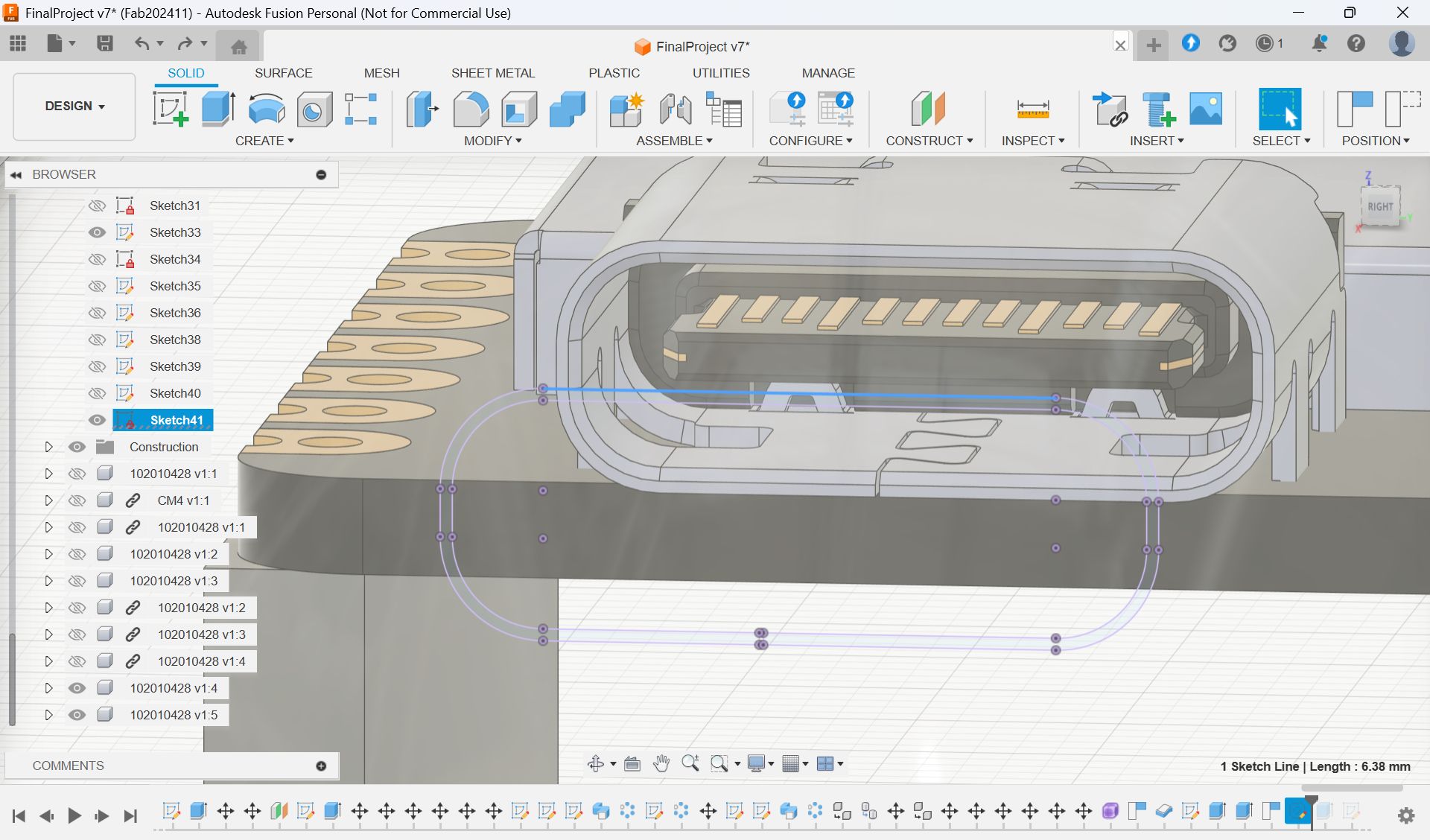
Download xiao model
https://www.digikey.jp/ja/models/14672129
Download Raspberry Pi model
https://pip.raspberrypi.com/categories/1204-design-files
https://pip.raspberrypi.com/categories/1096-design-files
Upload .step file and you can use 3d model of microcomputer
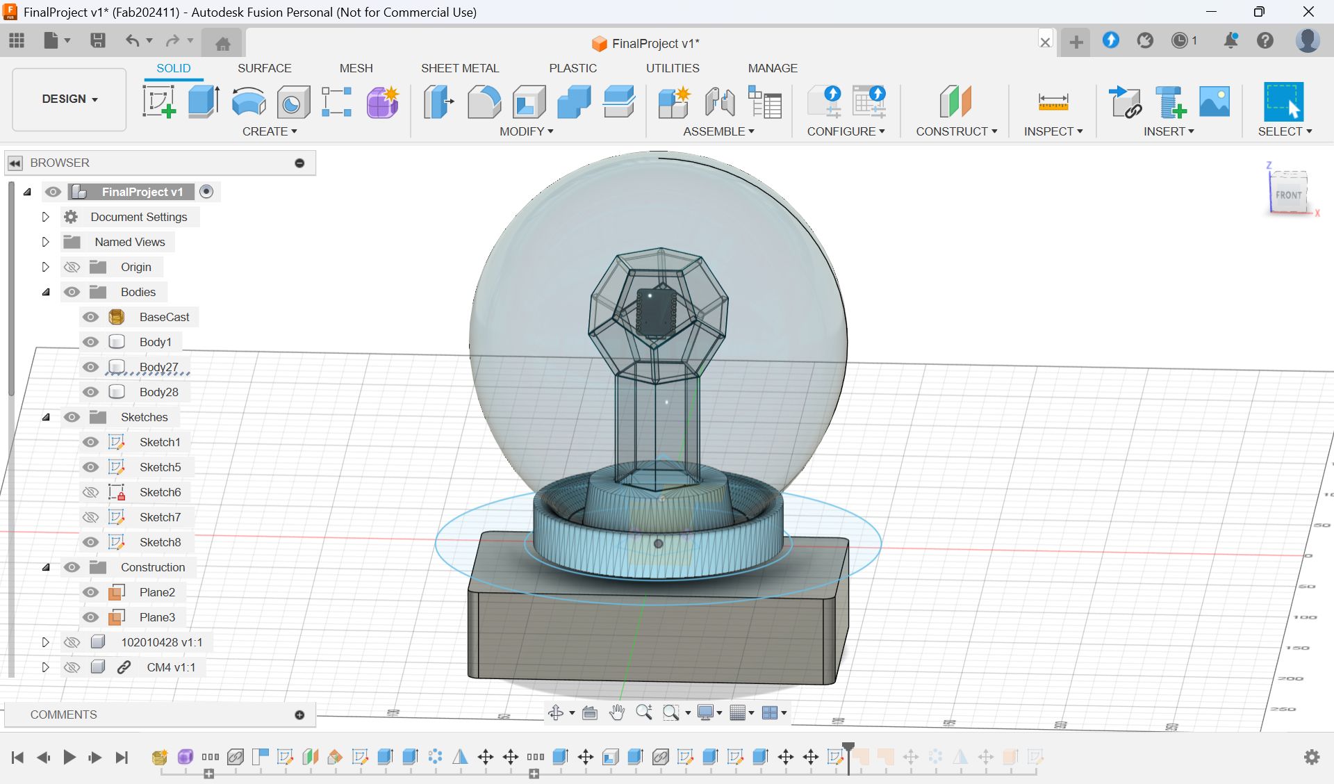
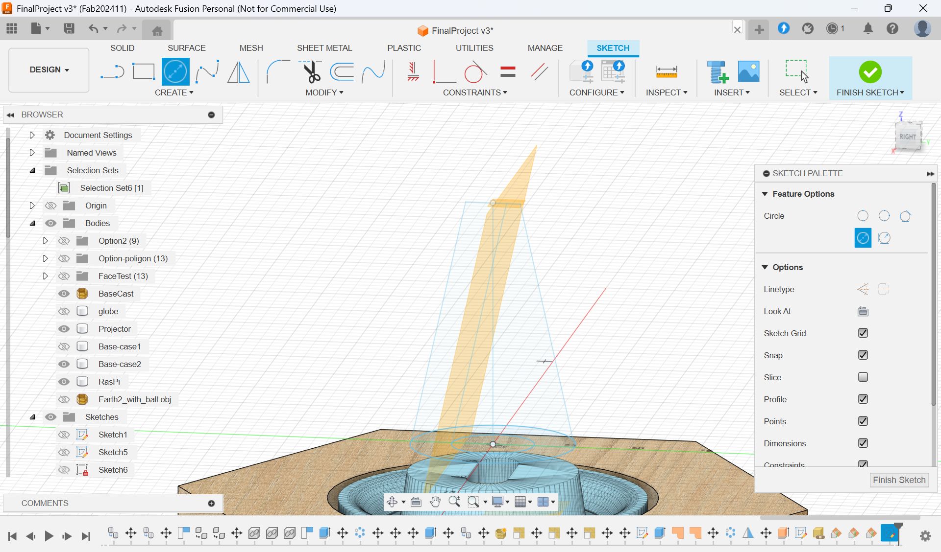
I also haven’t decided how to fix MCU on upper part, and also bottom part for projector, so I consider about it with making some designs and examined.

Tried laser cut sample 2 and 3. Sample 3 seems too big...
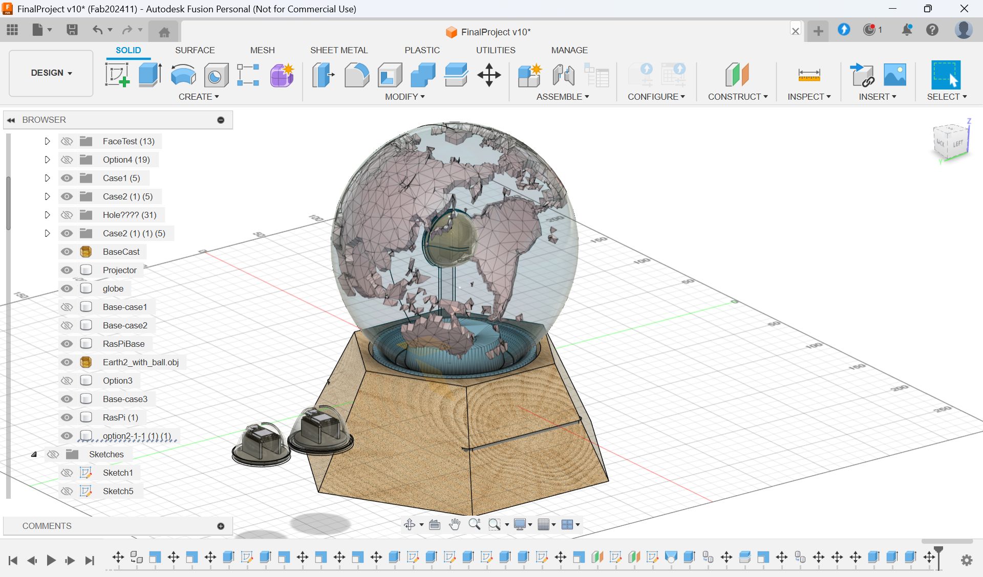
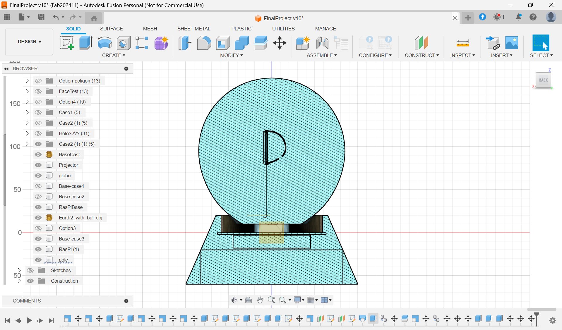
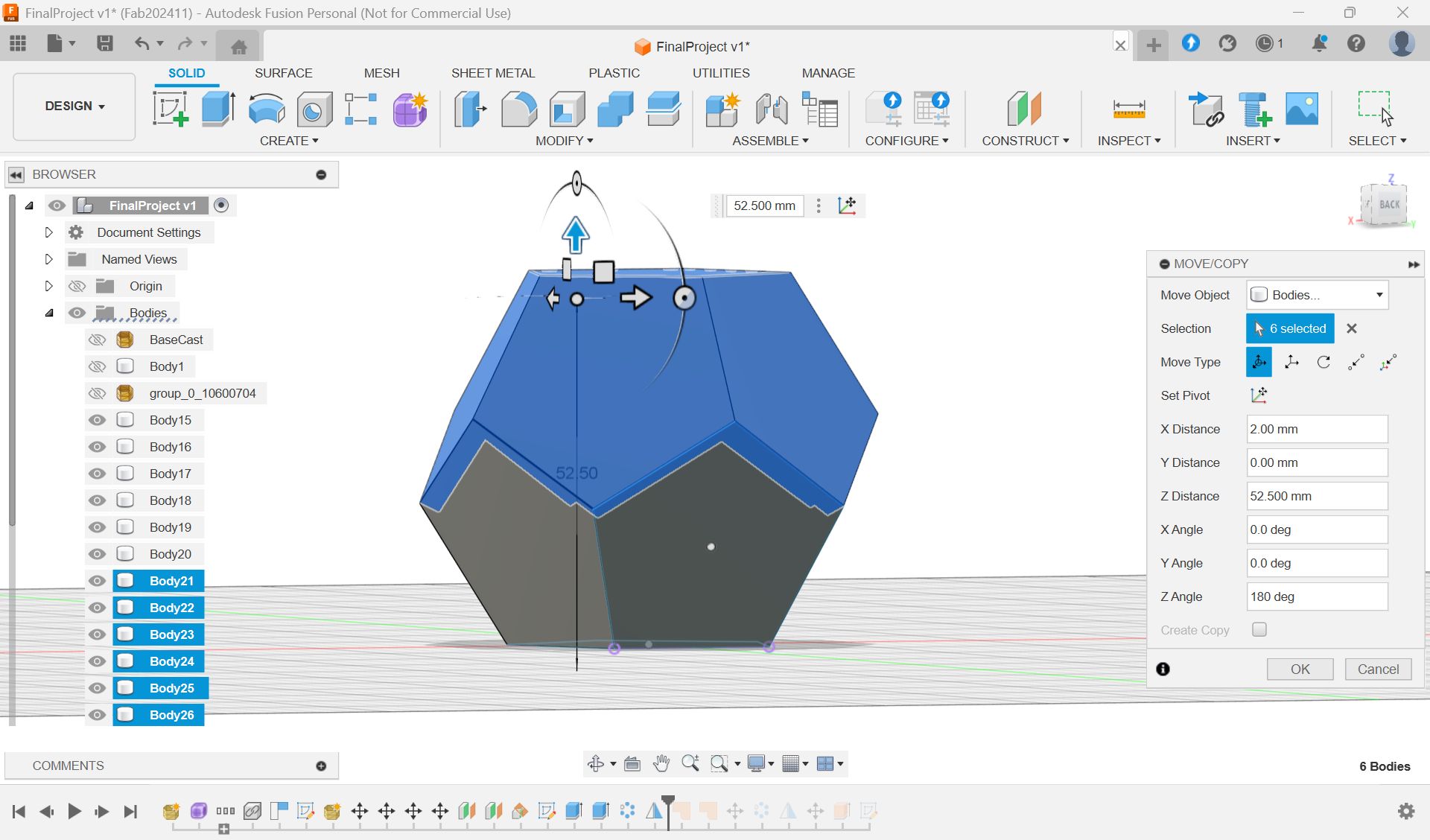
Final Model at this point:
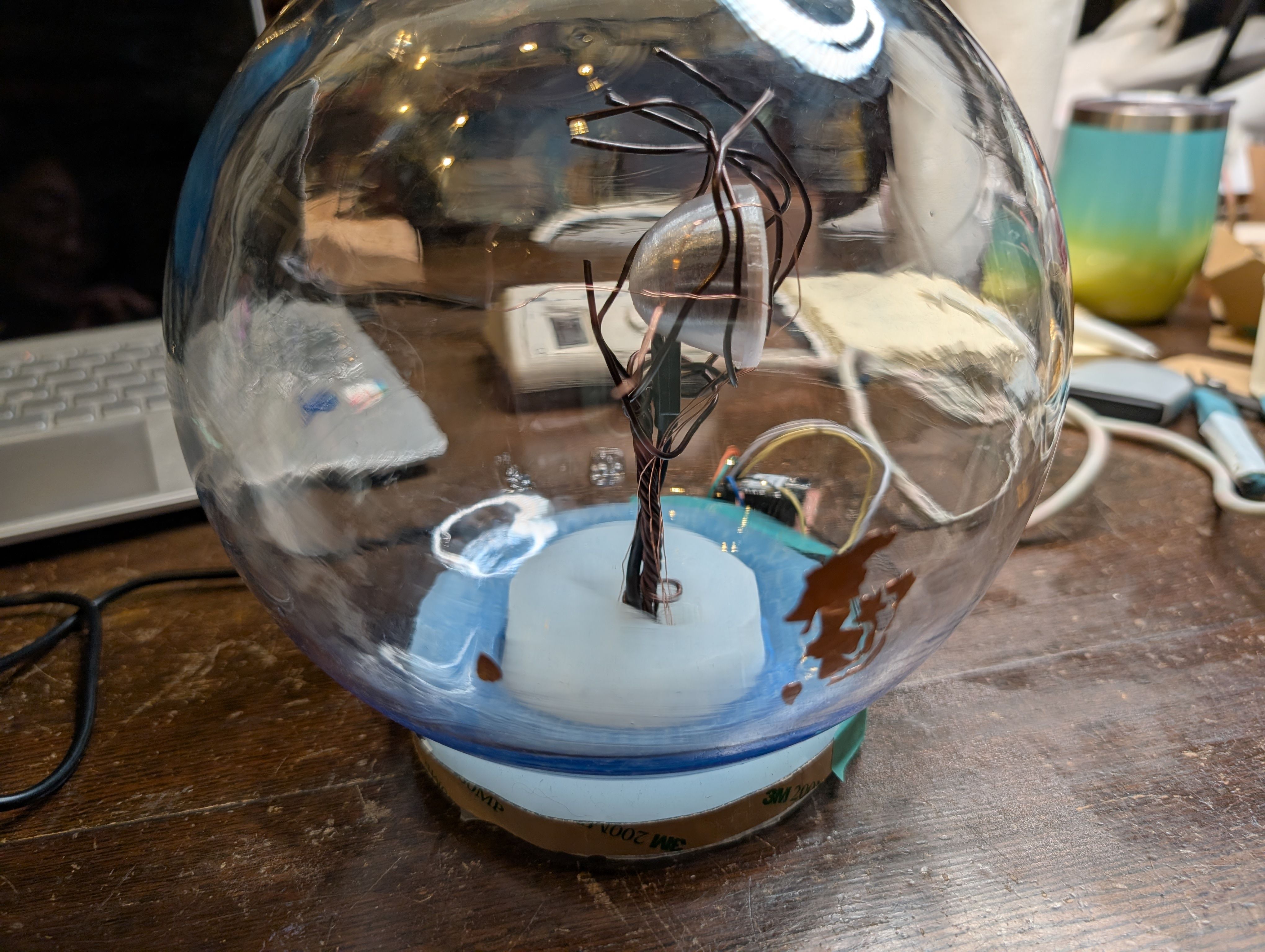
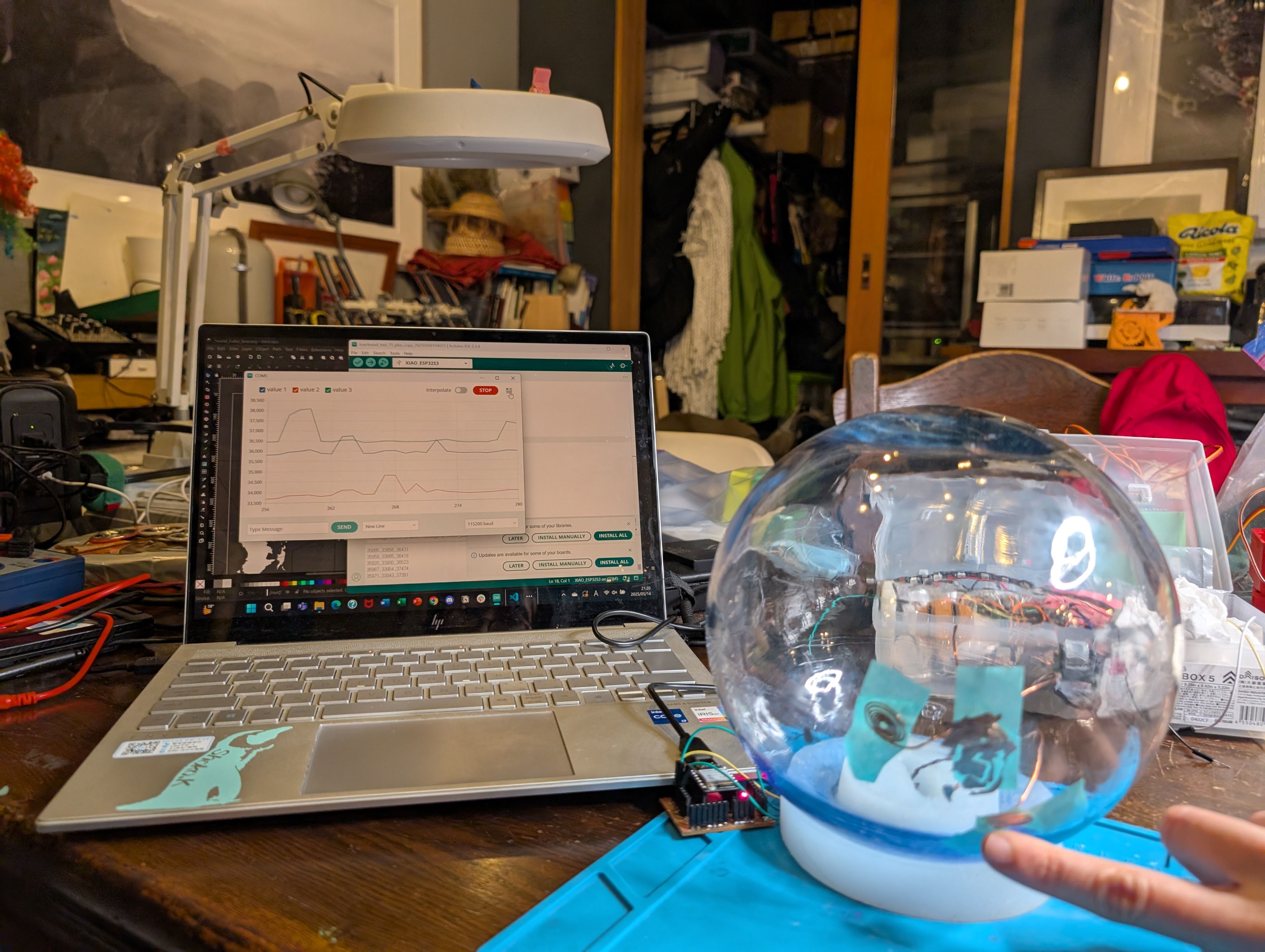
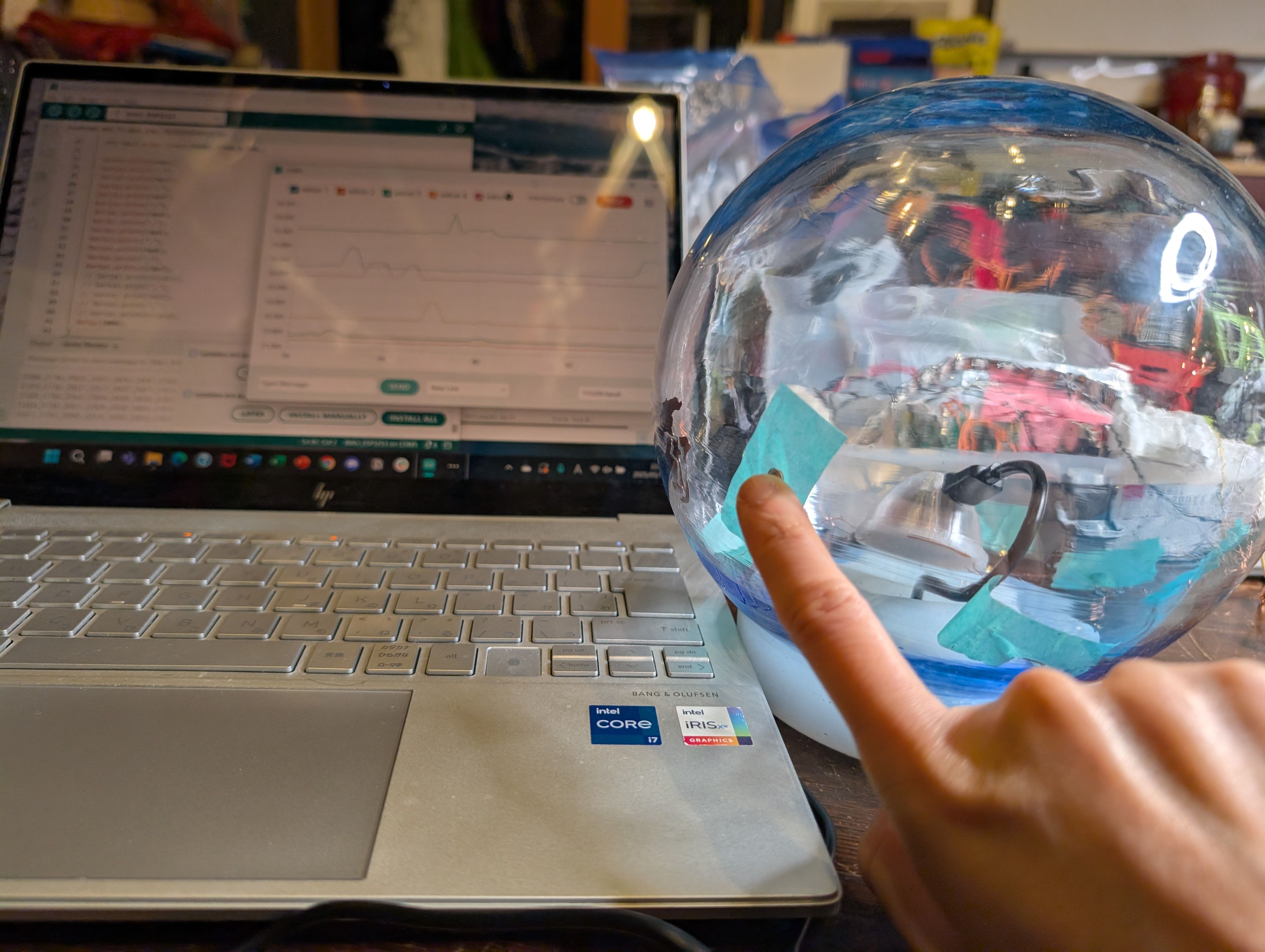
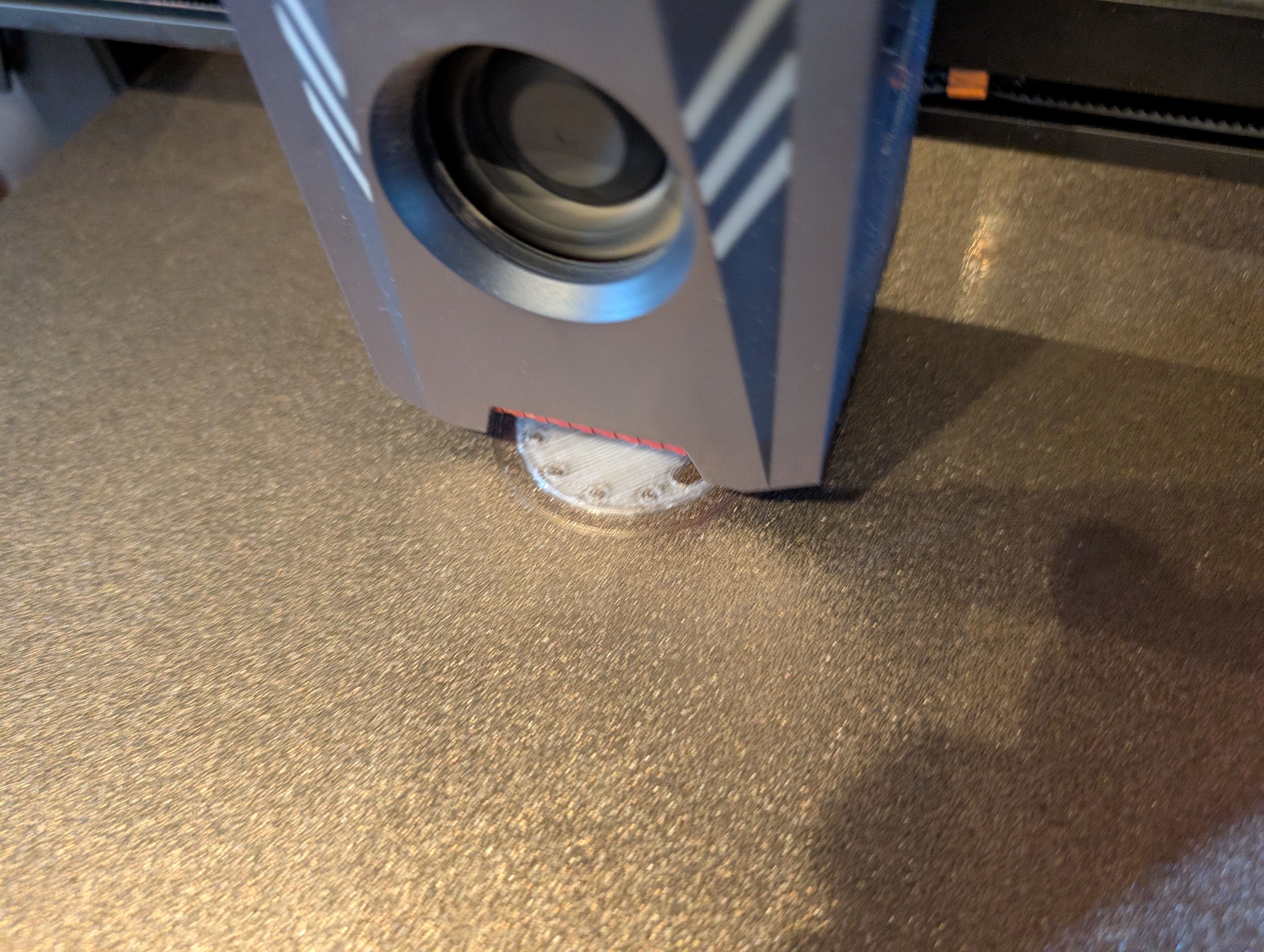
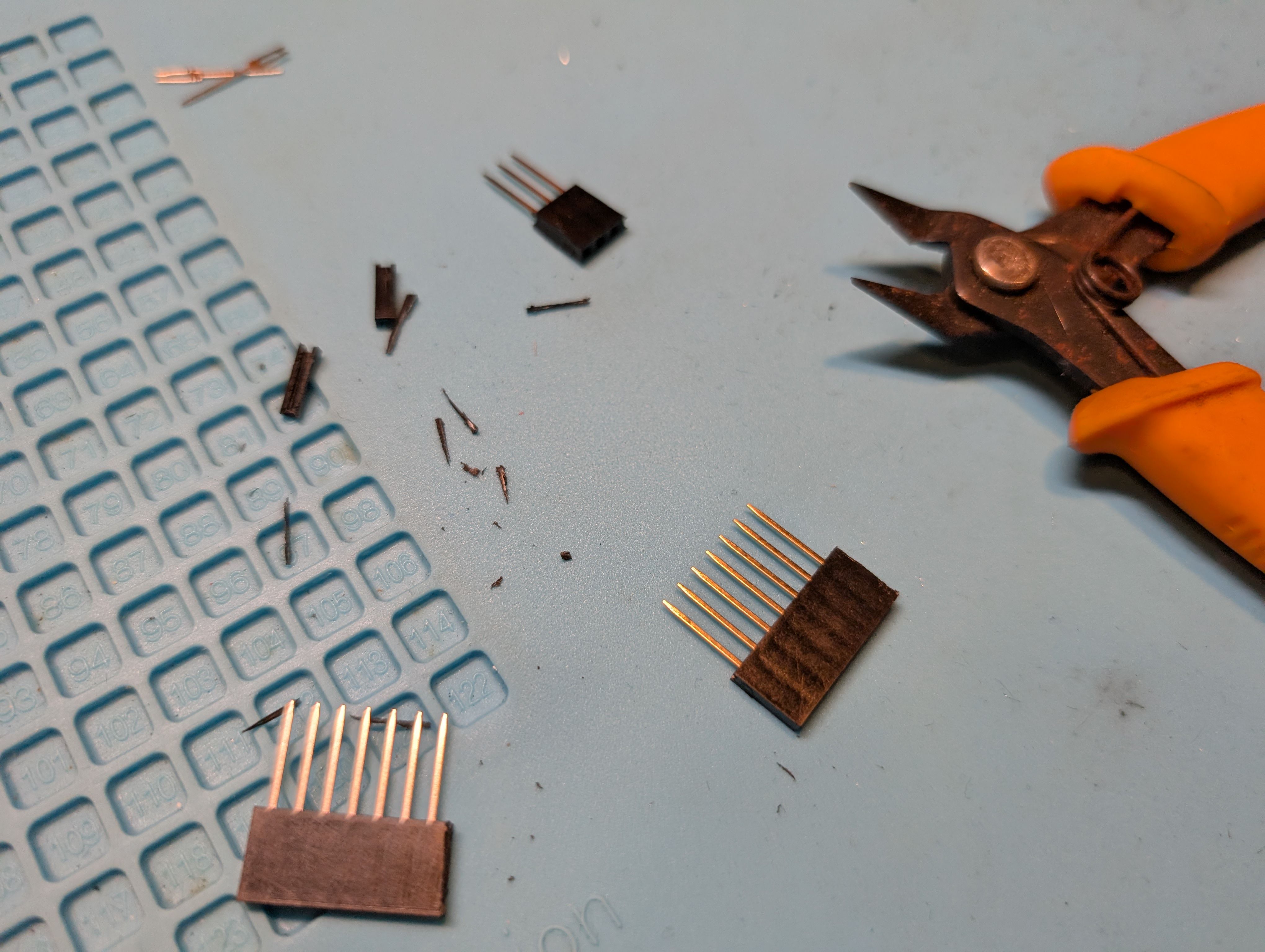
3. Assemble and check the wiring
Tried assemble the sensor(globe) part.
I found it seems difficult to put xiao and support parts and sensors at the same time, since the hole of the glass is too small.
So I tried to make the sensors bigger. This means at this point (for the first spiral) detect all countries is difficult, so first I will start trying with regions.
I tried 1:sensors only 2: sensors and a xiao only.
At least, the test code works ok and touch detected with both thick and thin wires.
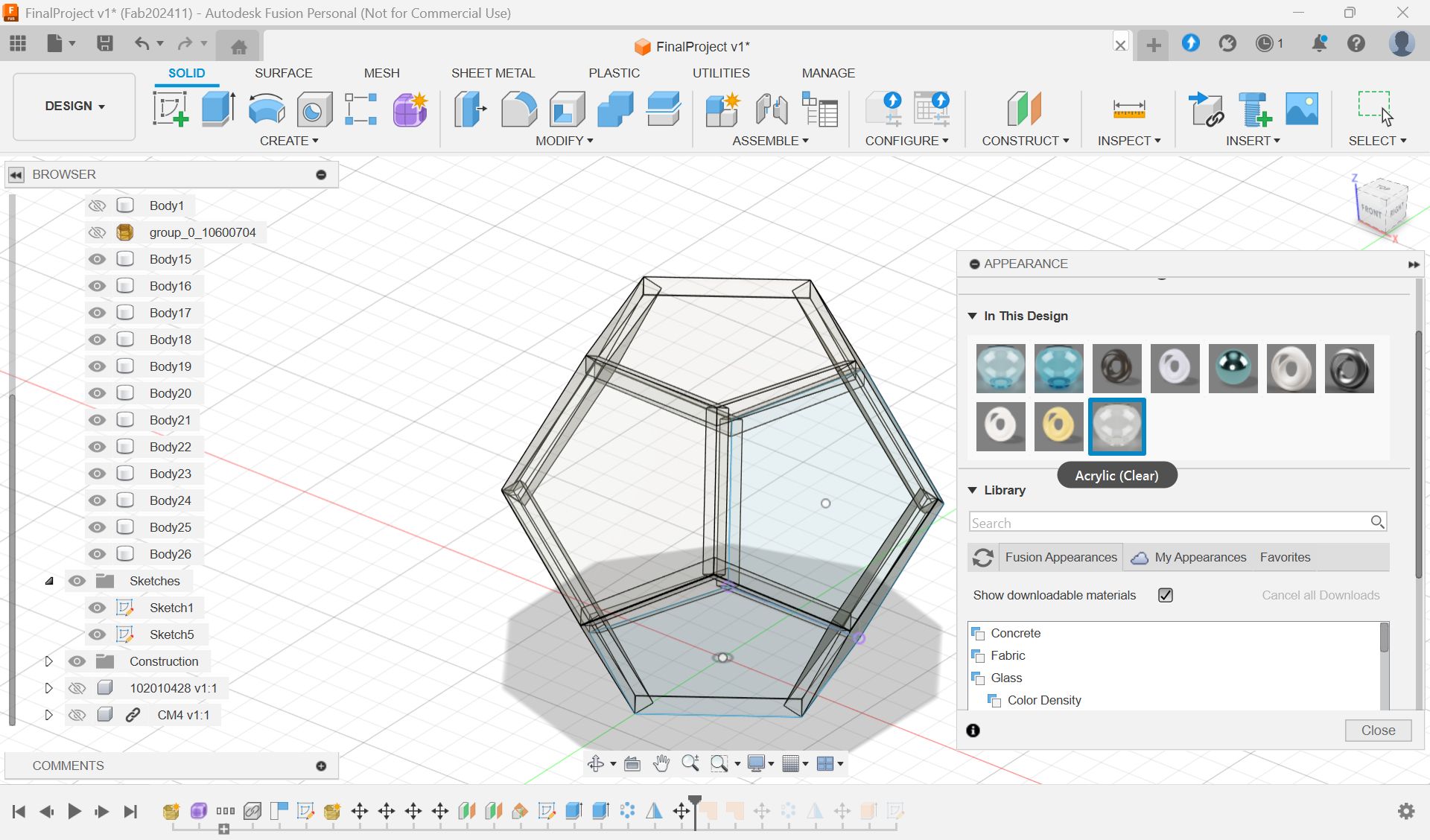
New things I tried with Fusion
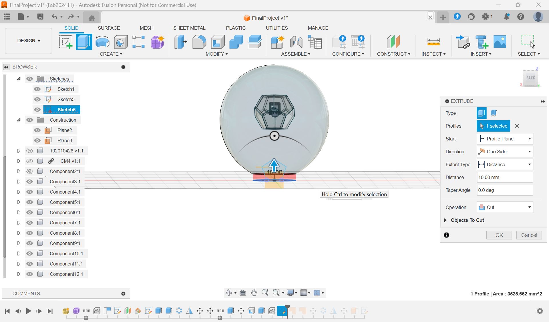
Change material(choose glass) and make it transparent
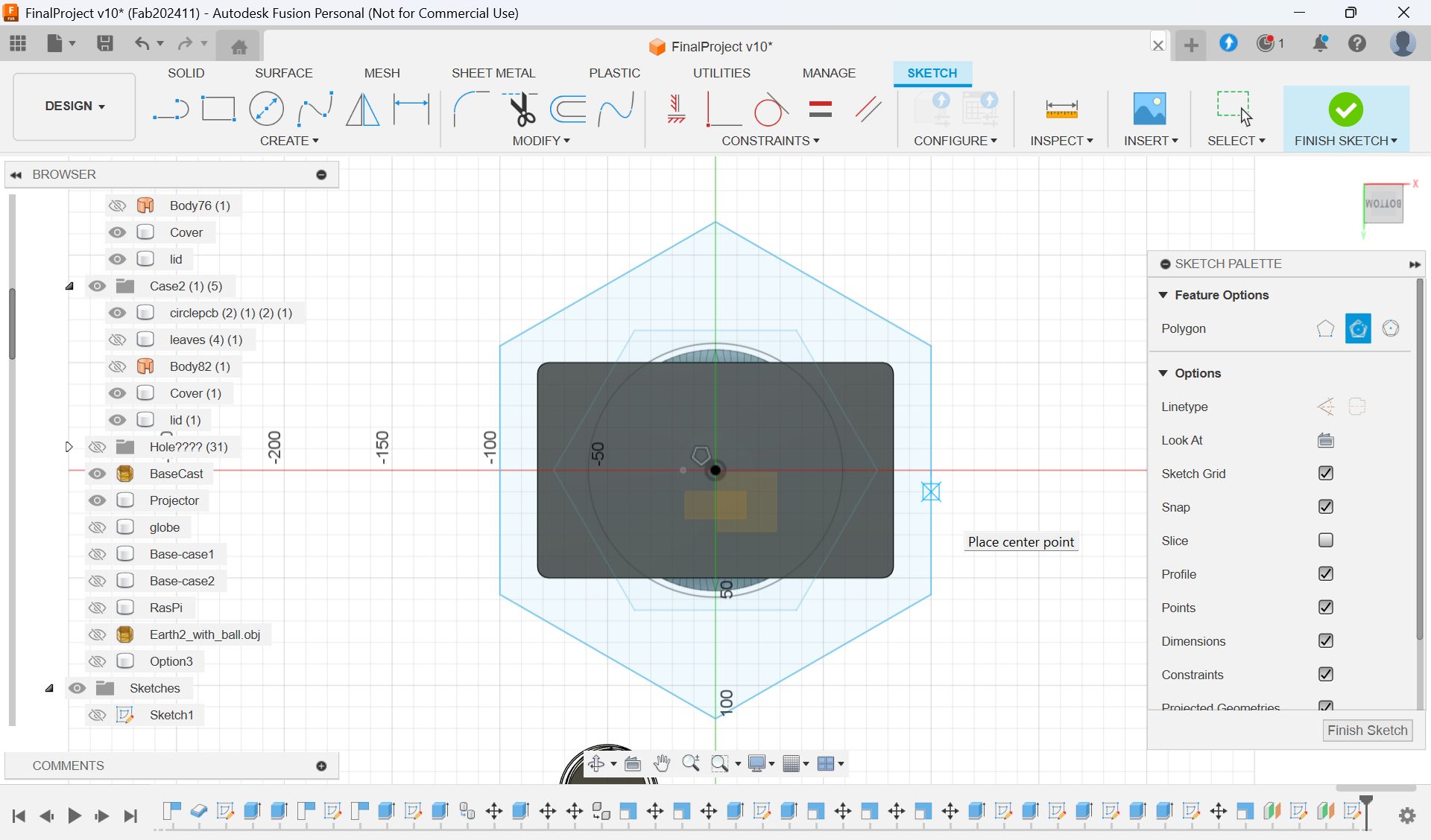
Option 1
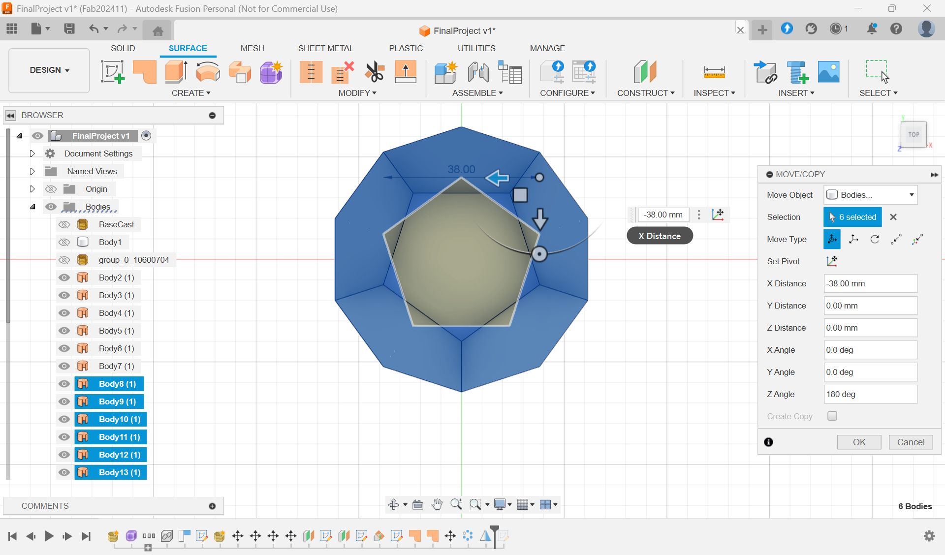
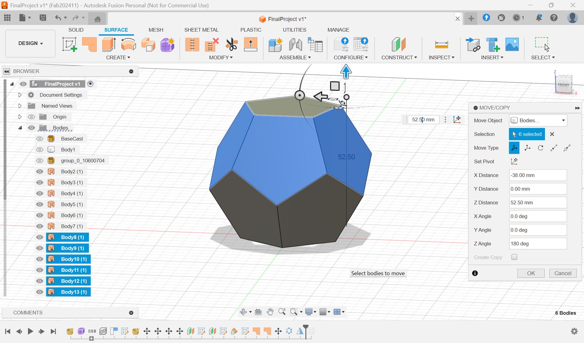
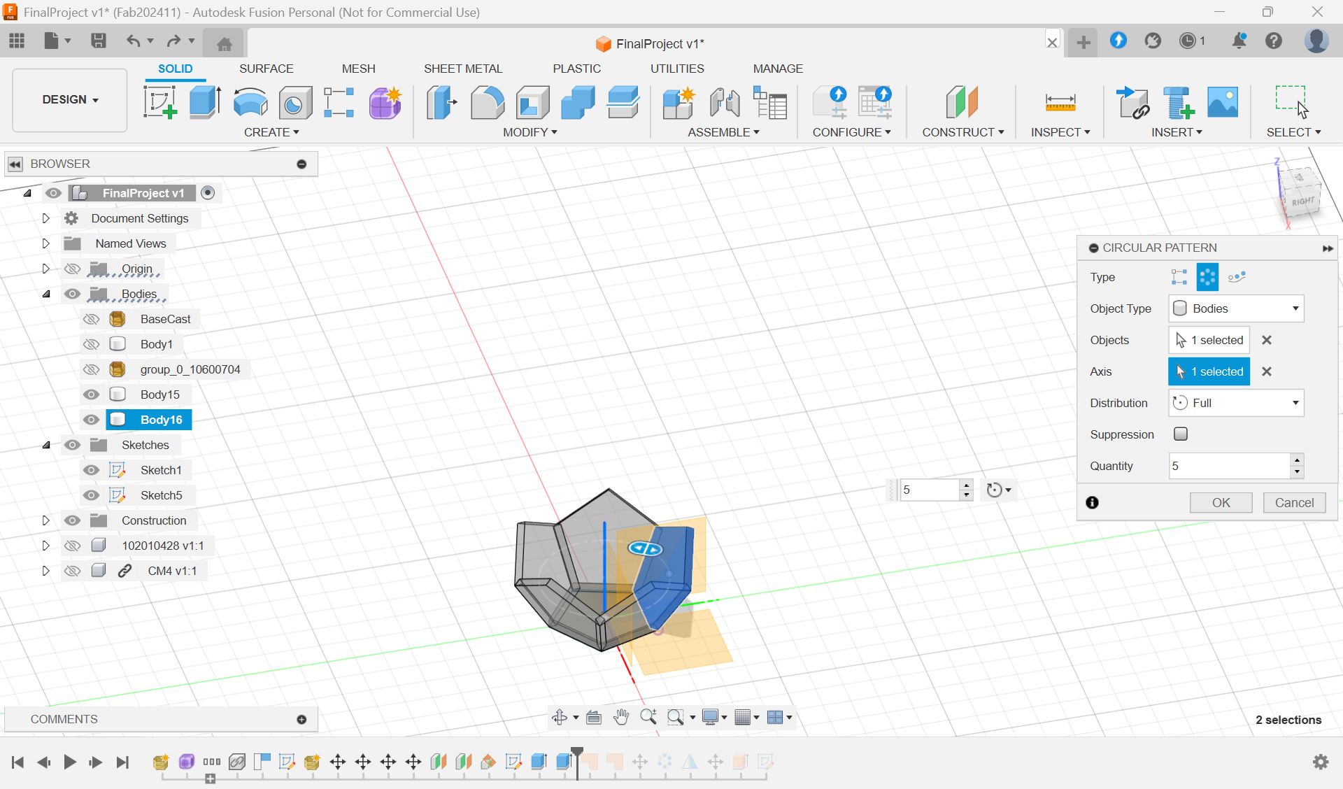
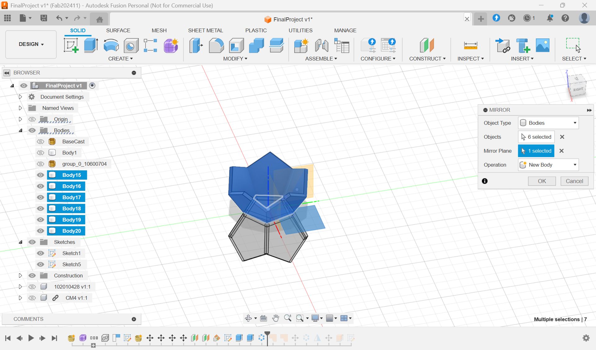
How to make regular dodecahedron
https://tas400kt.xyz/archives/1447
https://help.autodesk.com/view/ACDMAC/2024/JPN/?guid=GUID-F594A1AE-71B4-44D4-A867-AC95C43AF1E6
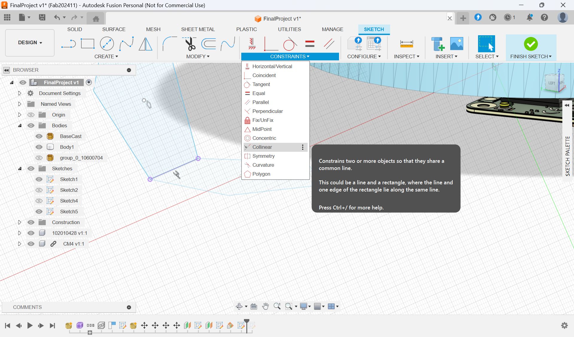
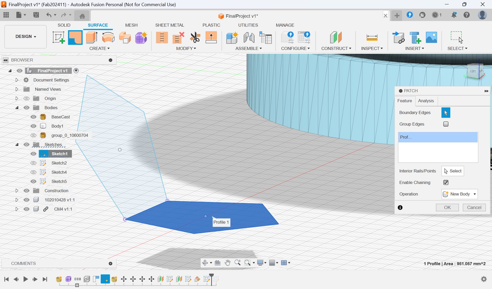
Surface > patch
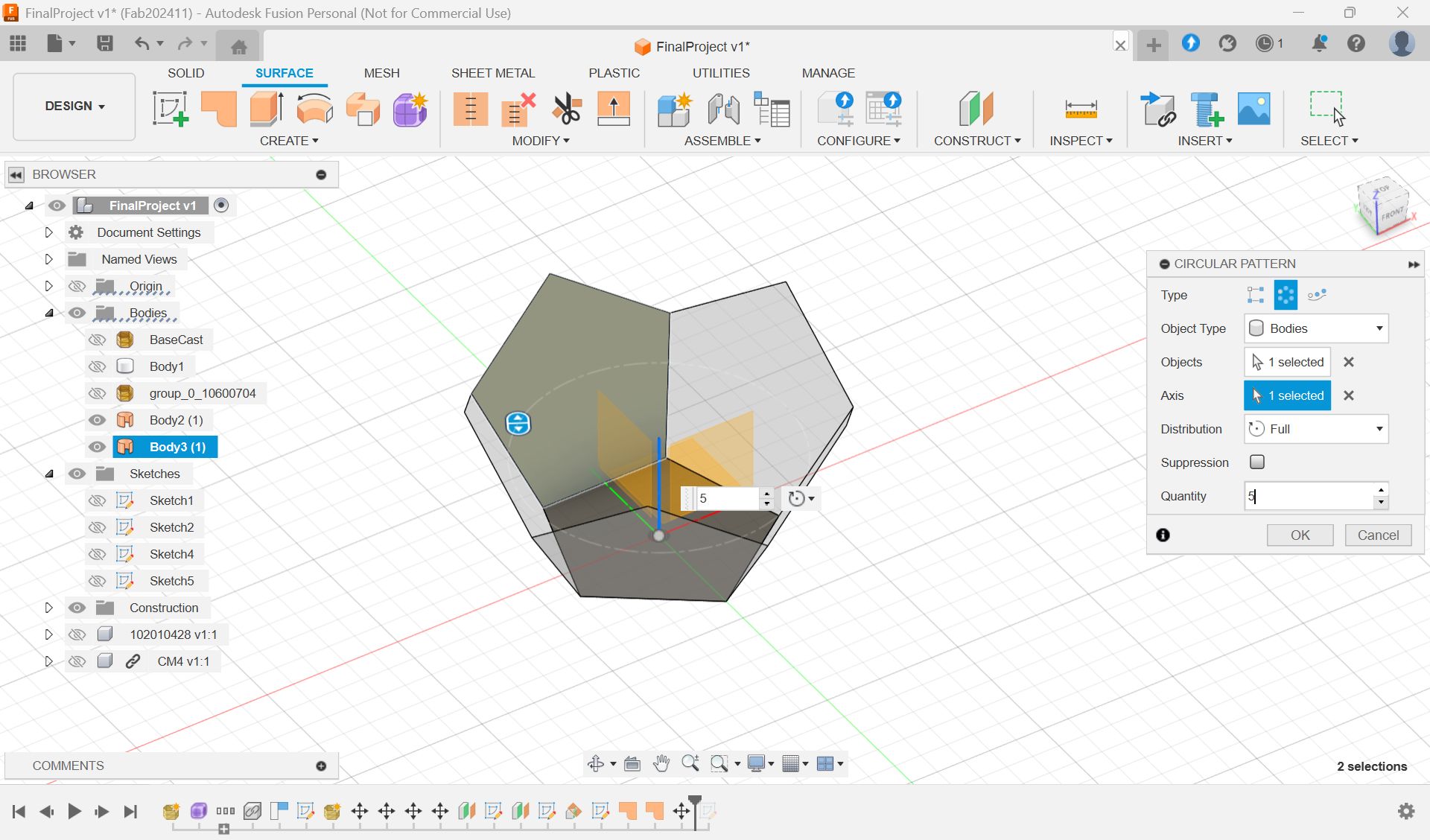
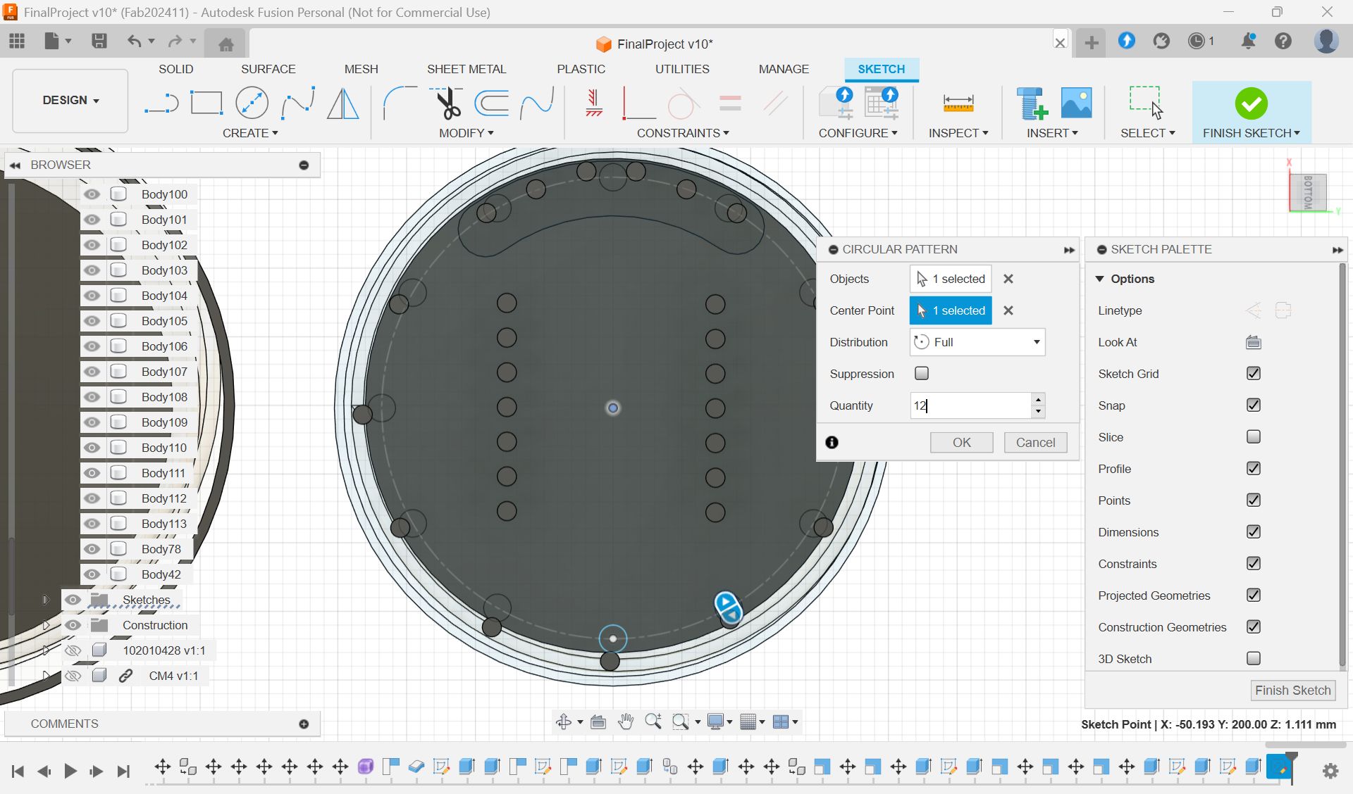
Pattern > circuler
Sample1
Sample2
Sample 3
Option 4
How to handle cables
https://forums.autodesk.com/t5/fusion-ri-ben-yu/keburunomoderu-huanitsuite/td-p/8756796
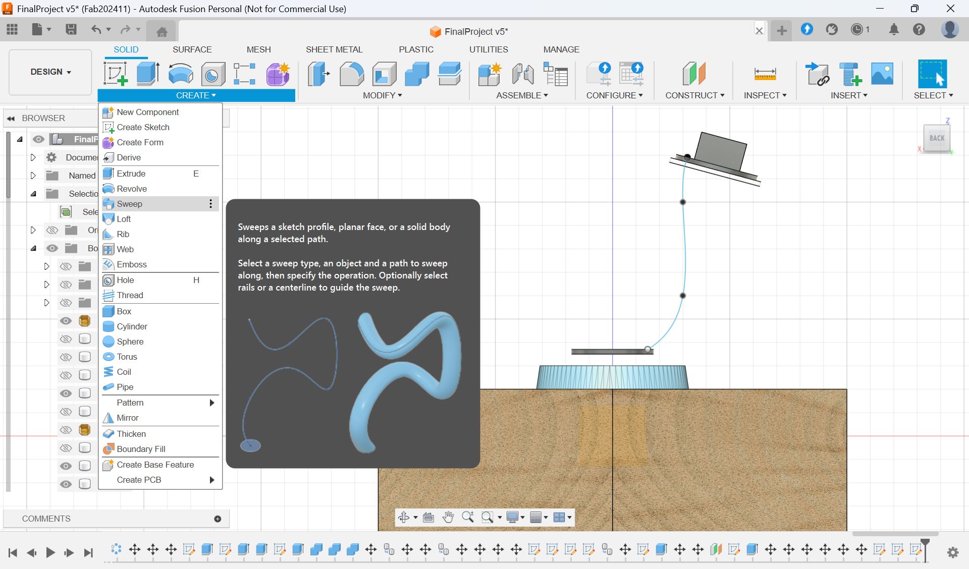
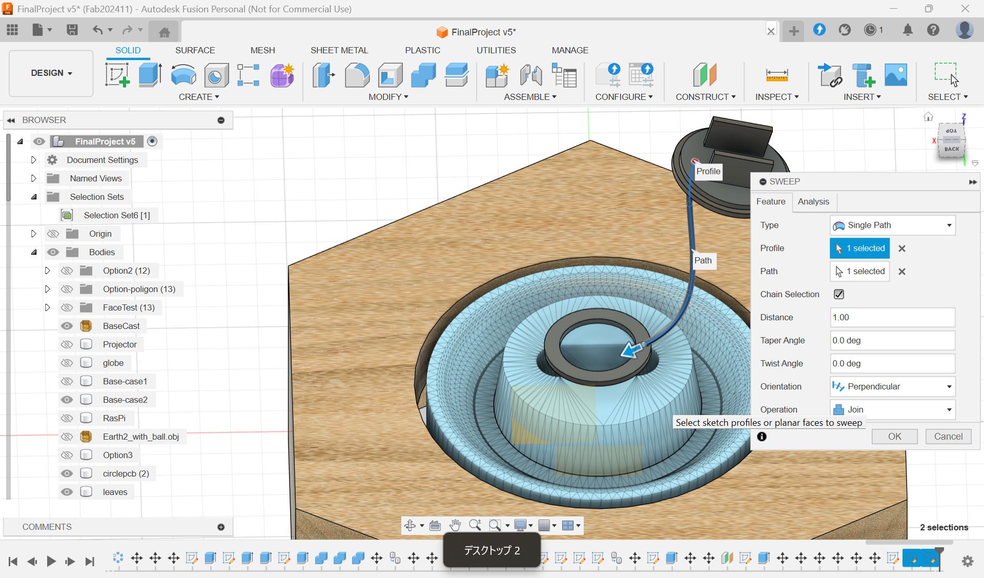
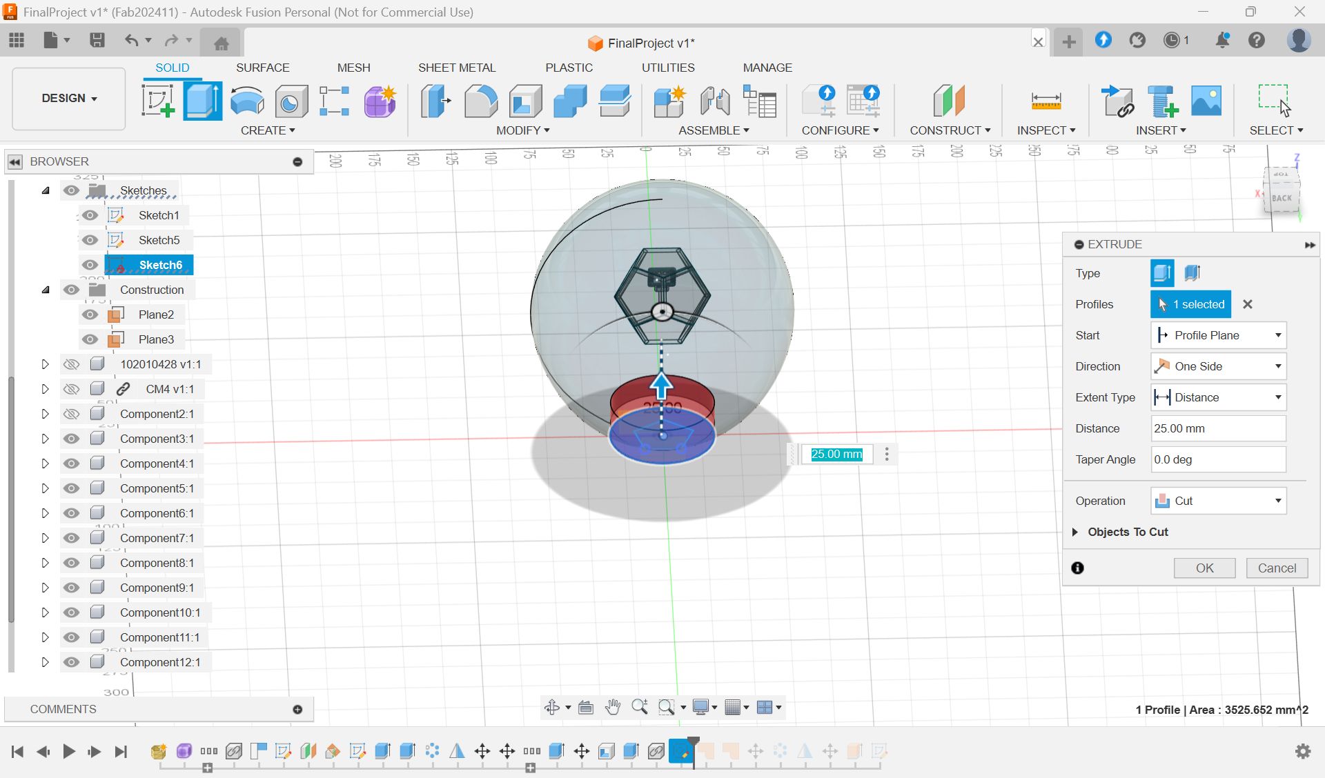
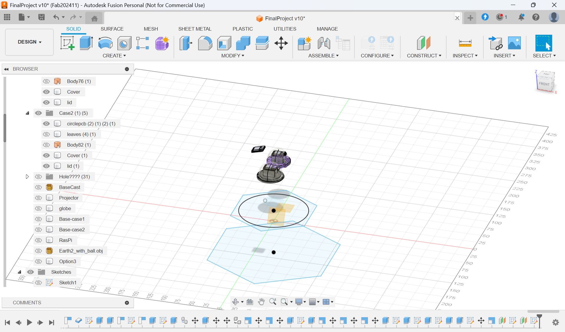
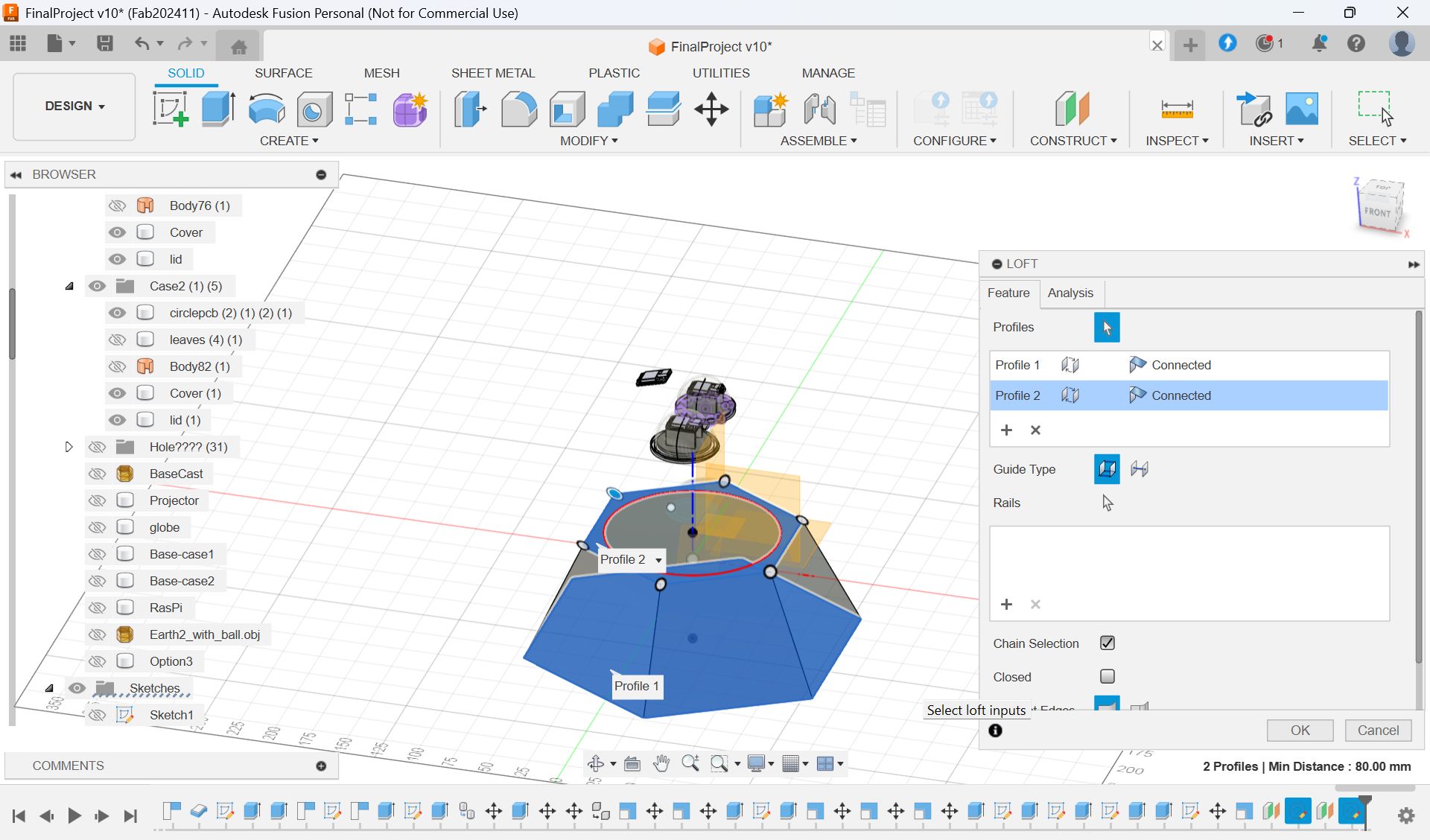
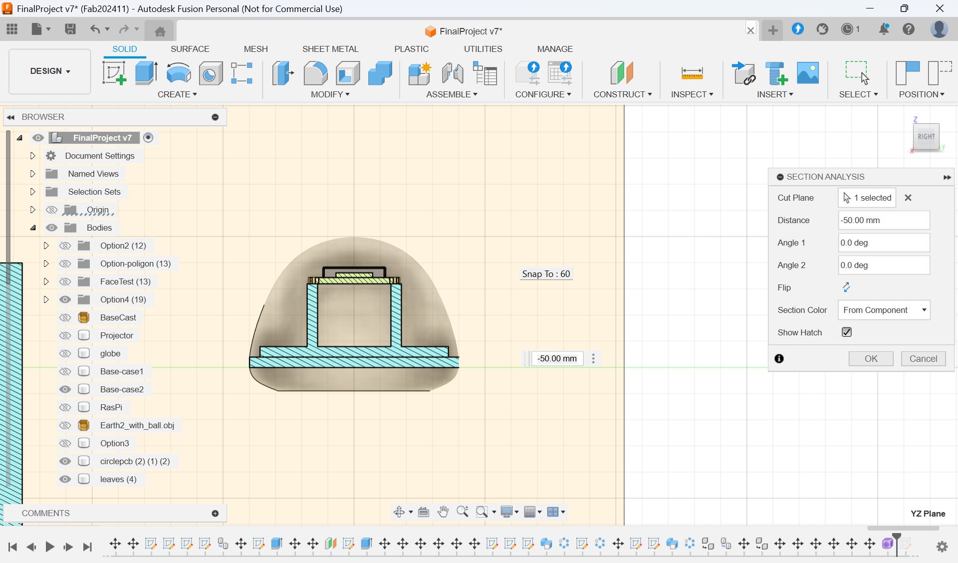
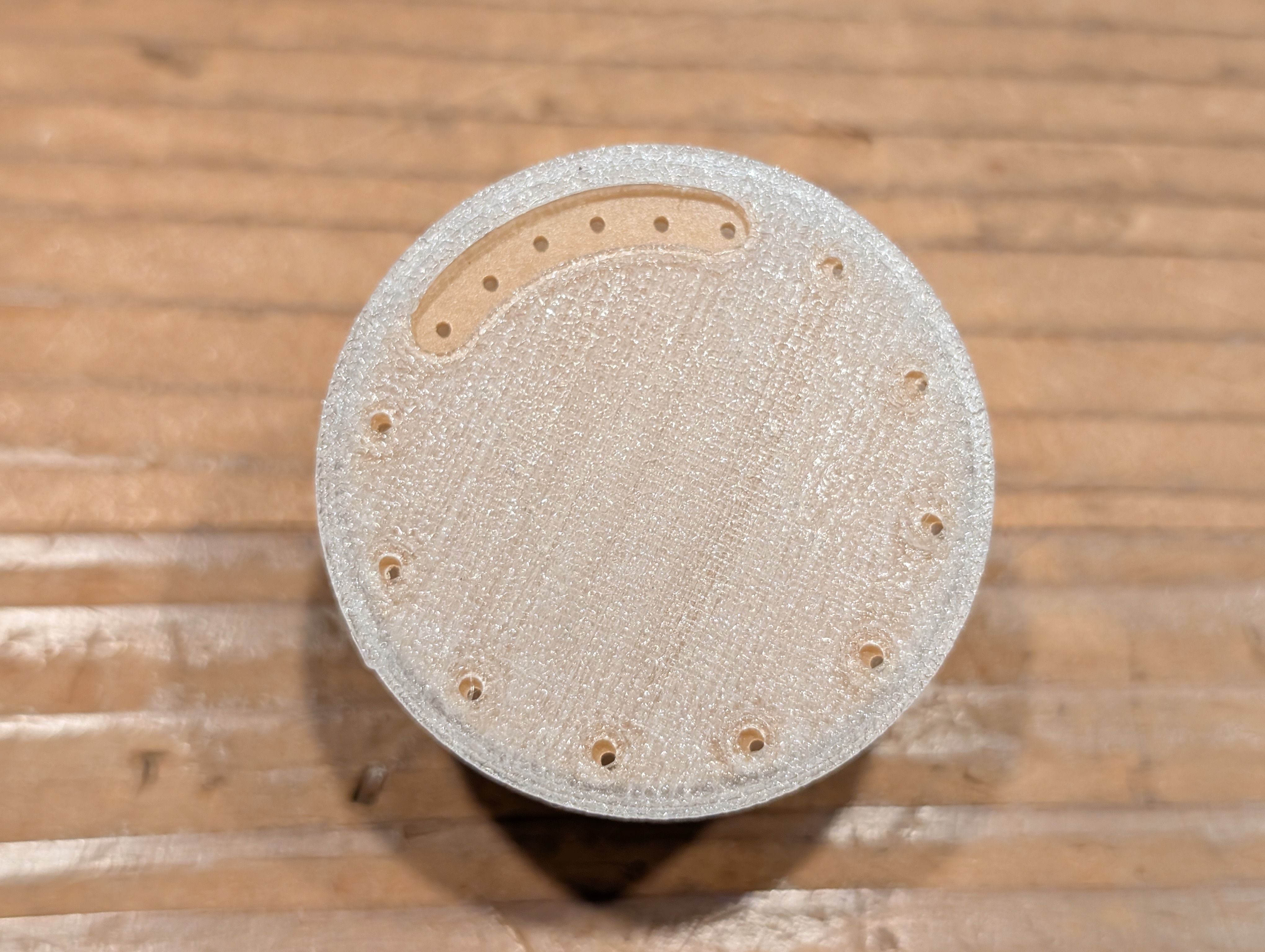
Final Base part design: use Loft
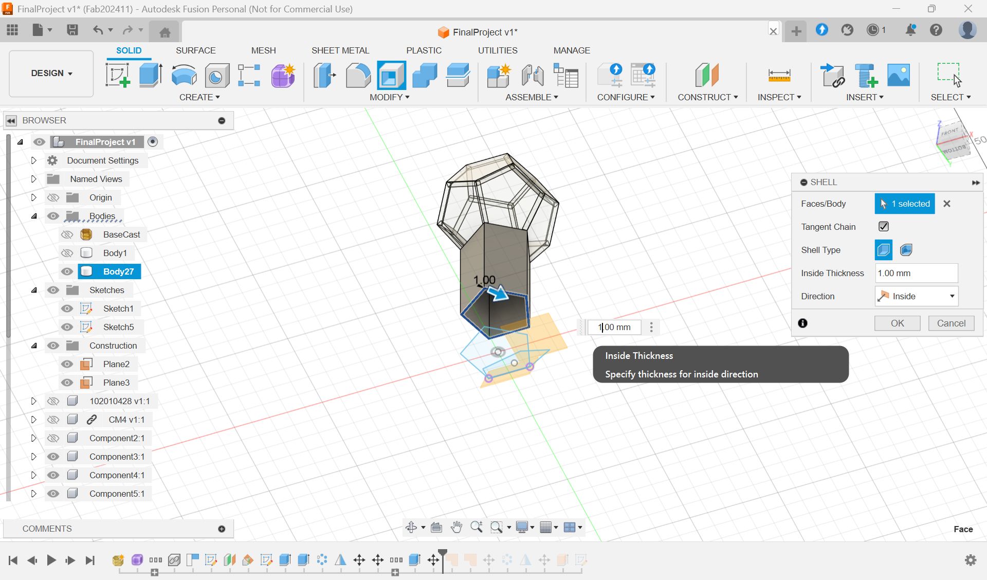
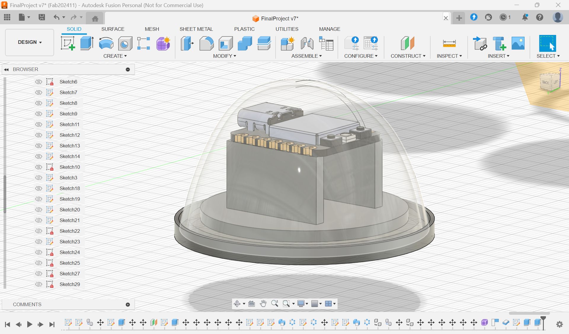
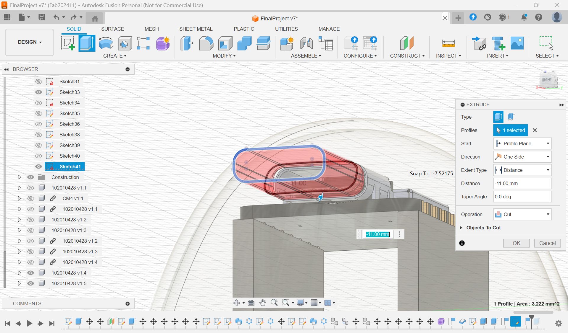
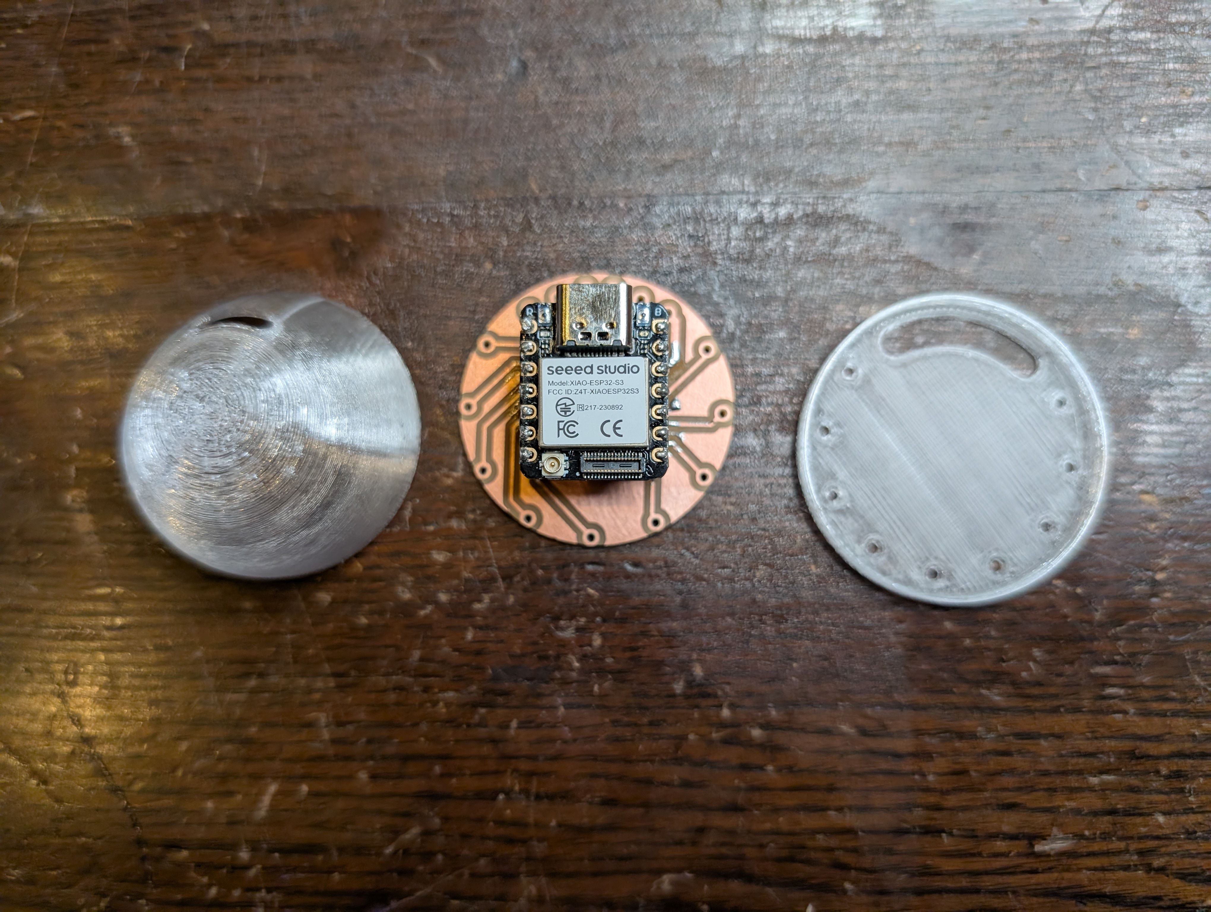
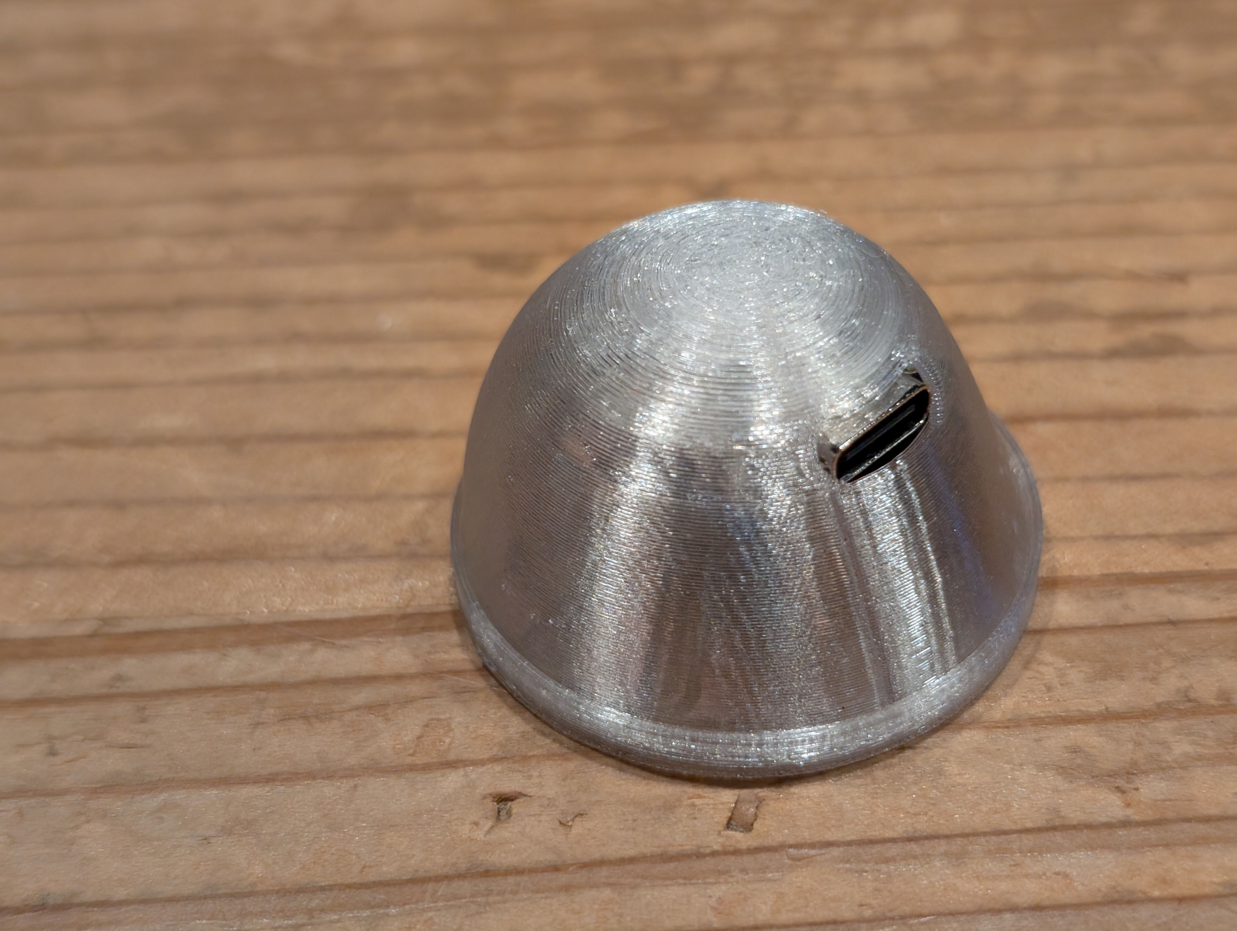
For assemble - made a xiao case
At least, I wanted to consider about the sensor part, and whatever the design, I thought it will be nice if xiao is in the case and hidden, so first I tried to make a case.
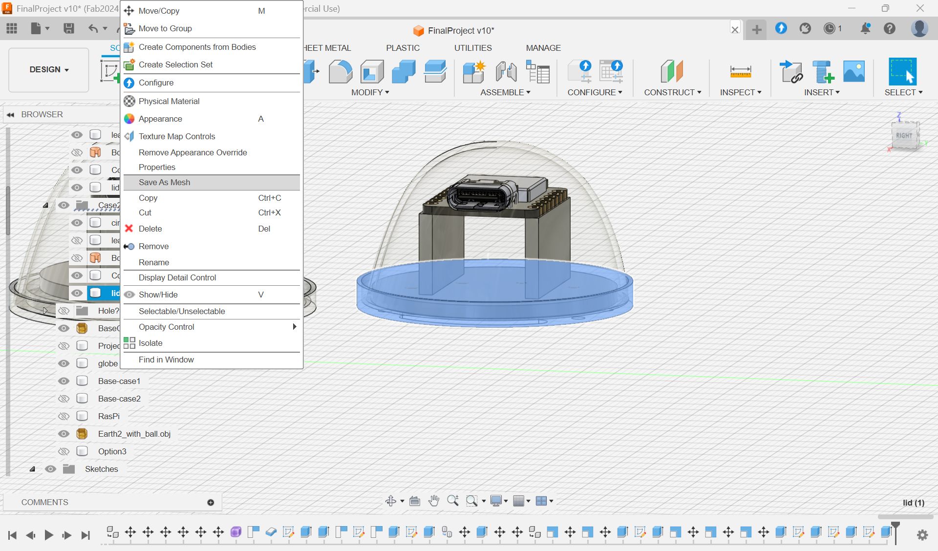
Made a case for xiao
Select parts”body”, and Save As Mesh, and export as stl file for 3D print

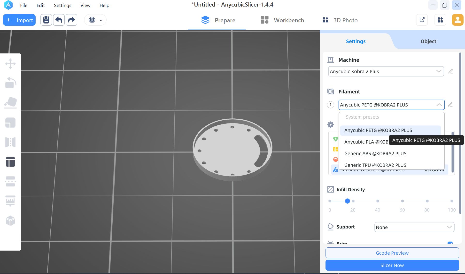
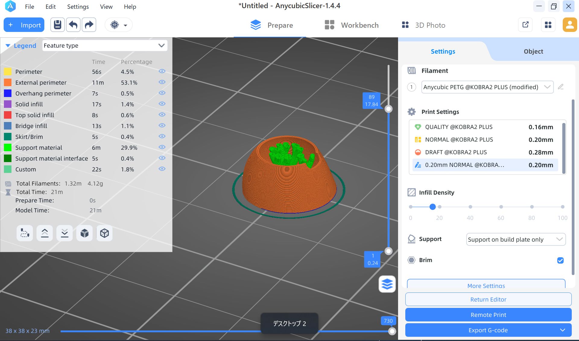
3D print settings
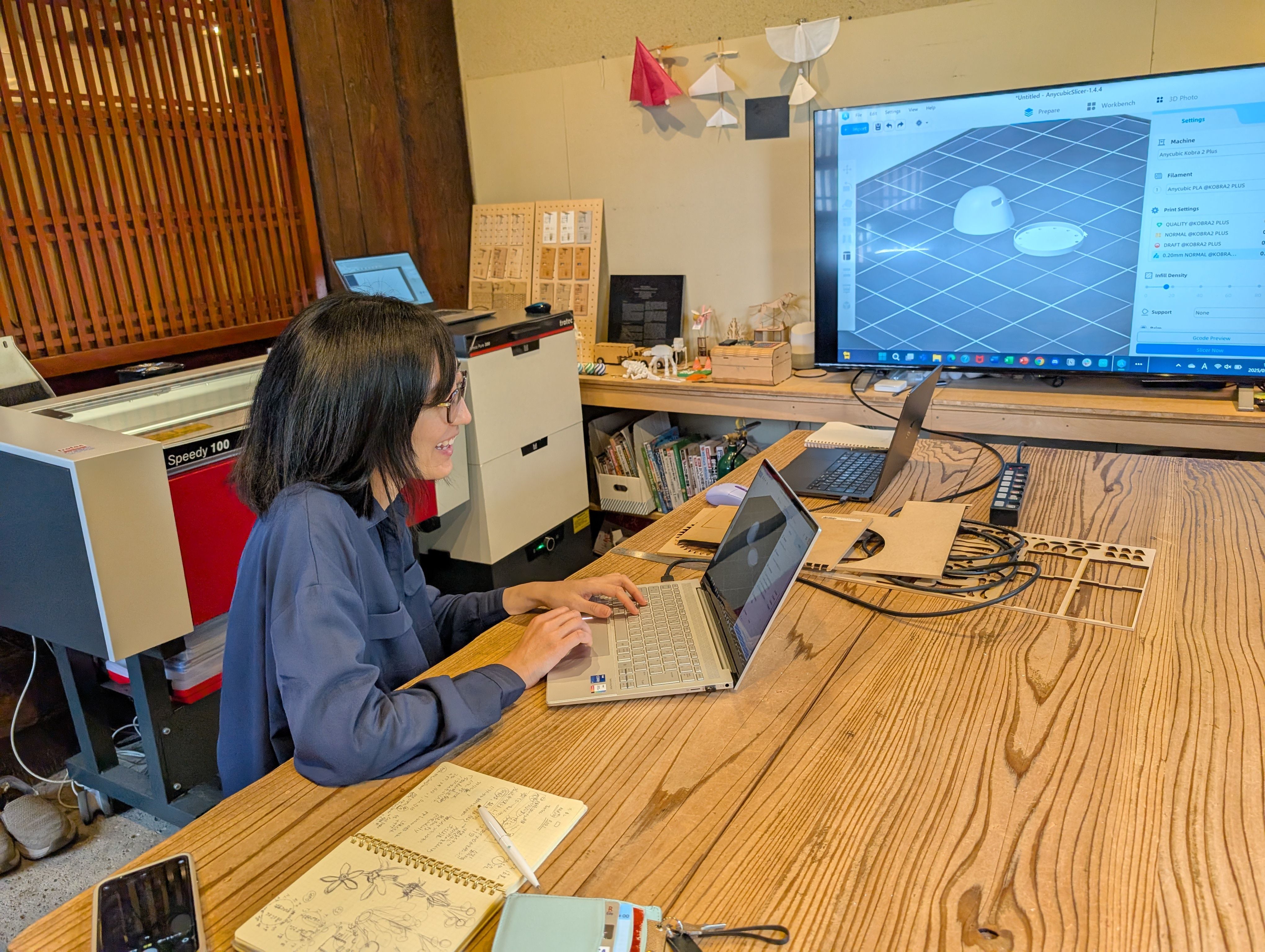
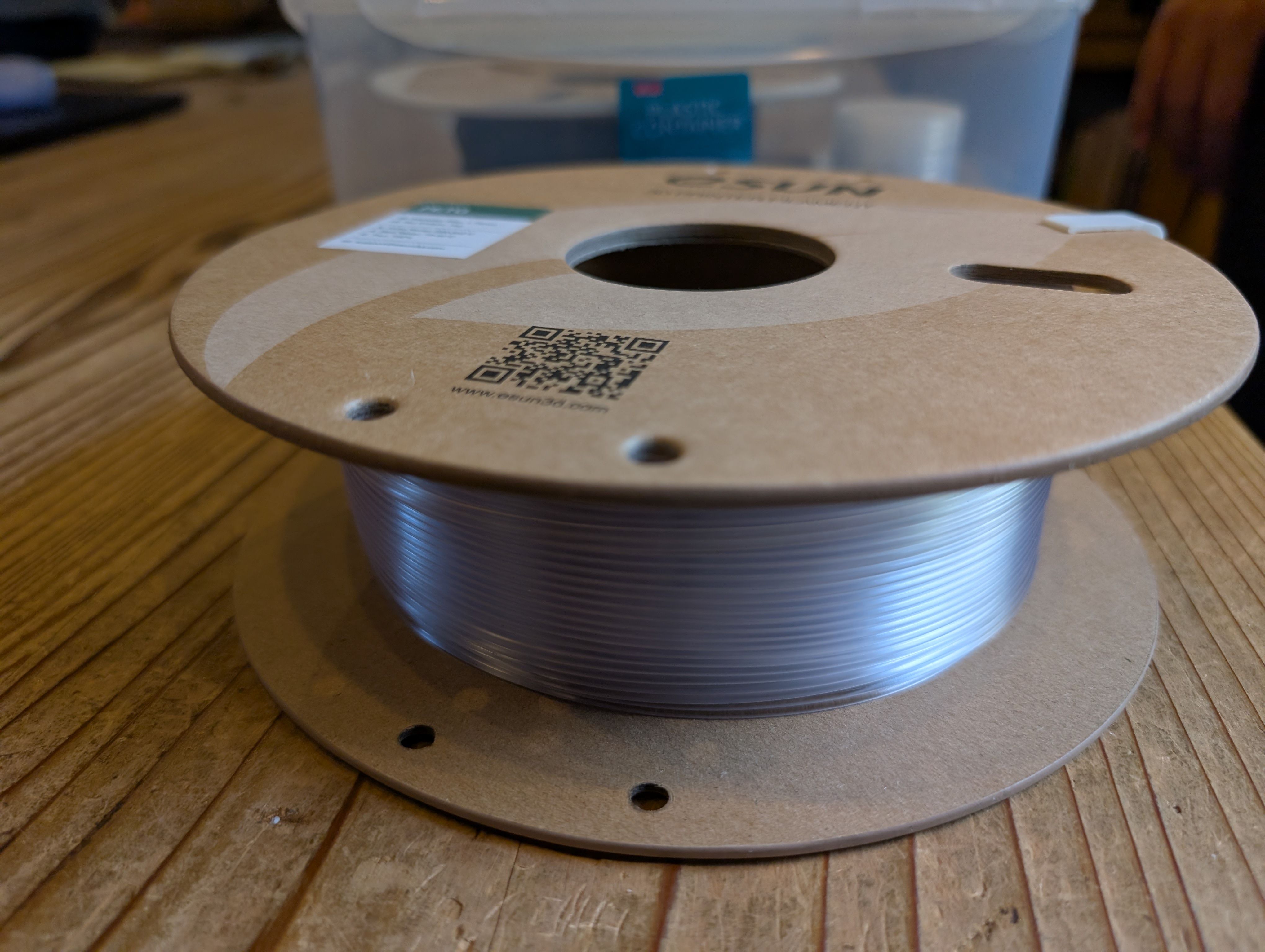
I used PETG (clear color), since it is clearer than PLA (recommended by Yamamoto-san)
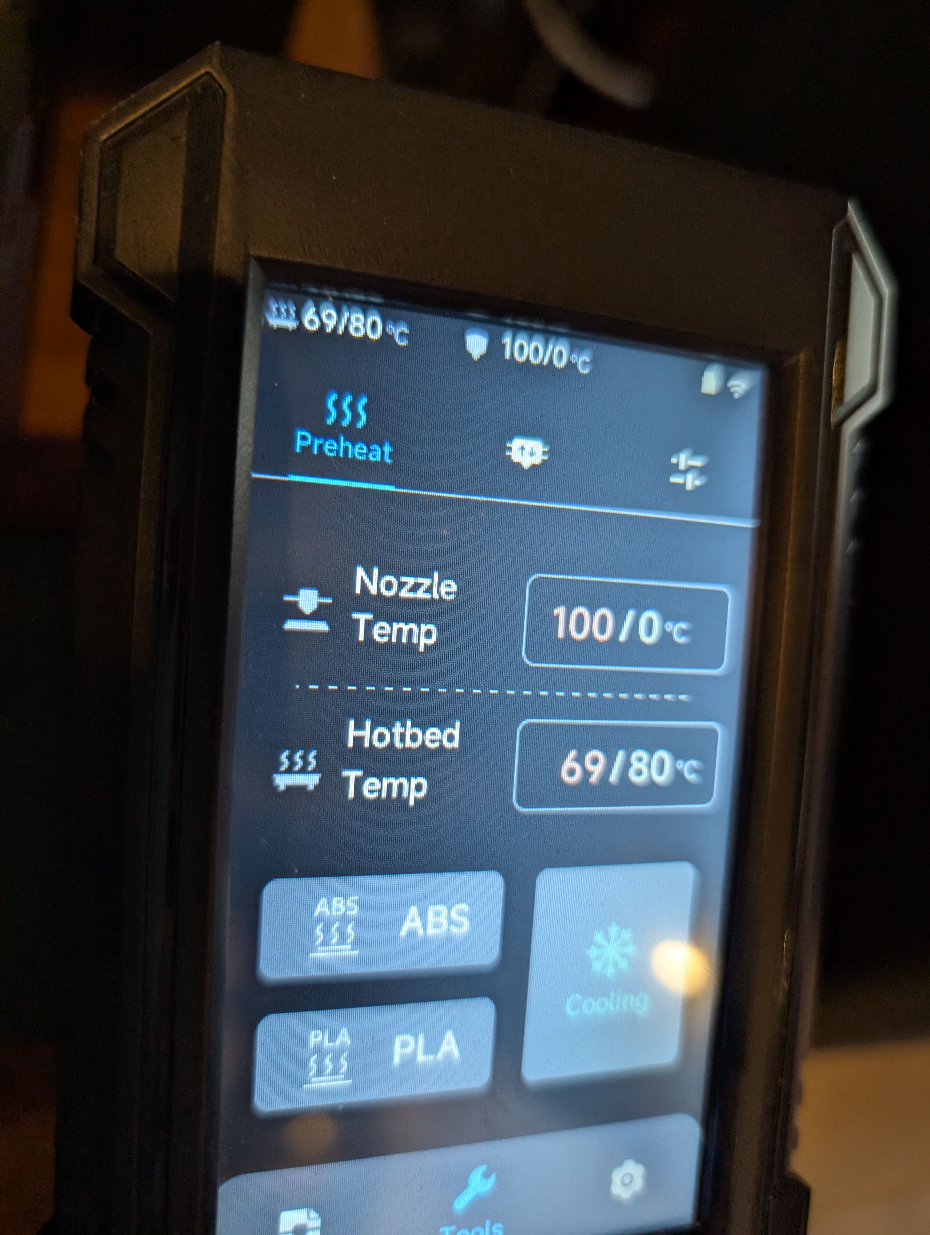
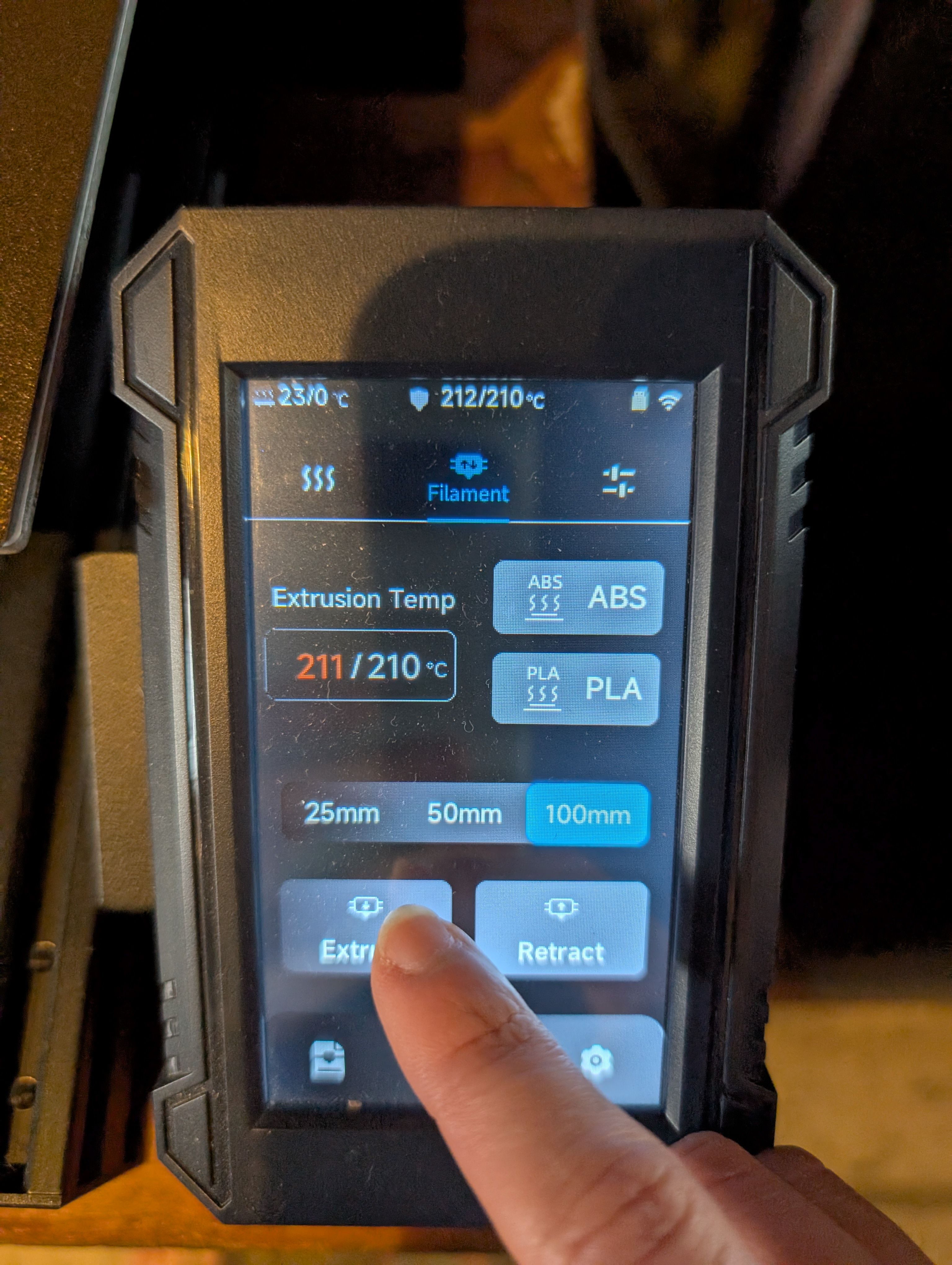
Head temperature: 250 - Changes transparency Bed temperature: 80 - Changes adhesion to the bed
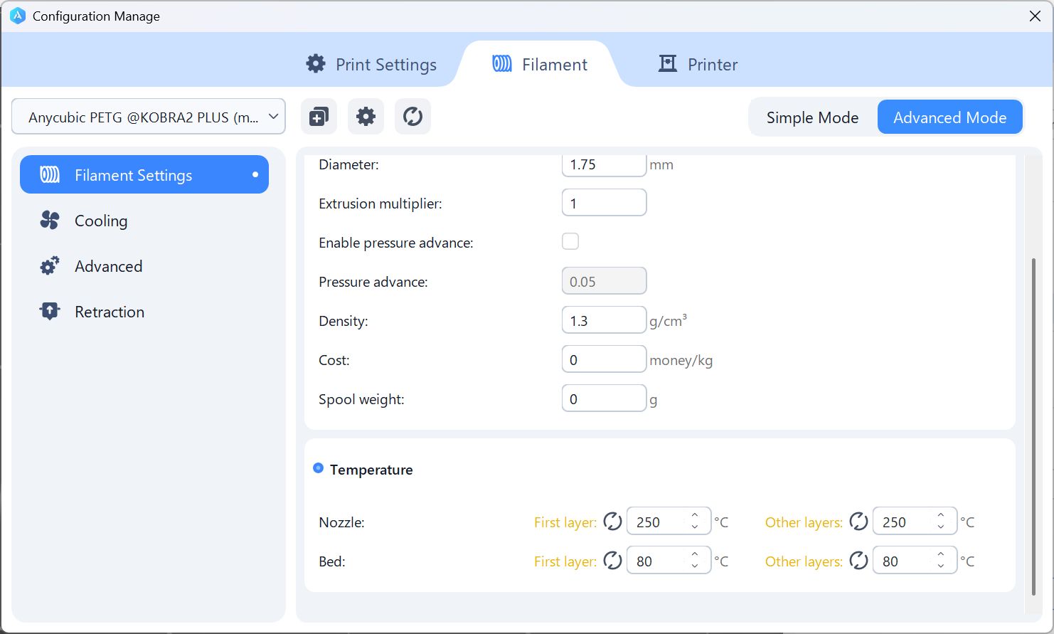
First layer: first layer Other layers: layers after 2
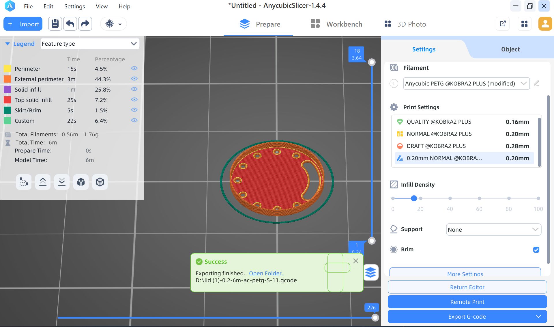
For a lid, no support, since it is flat
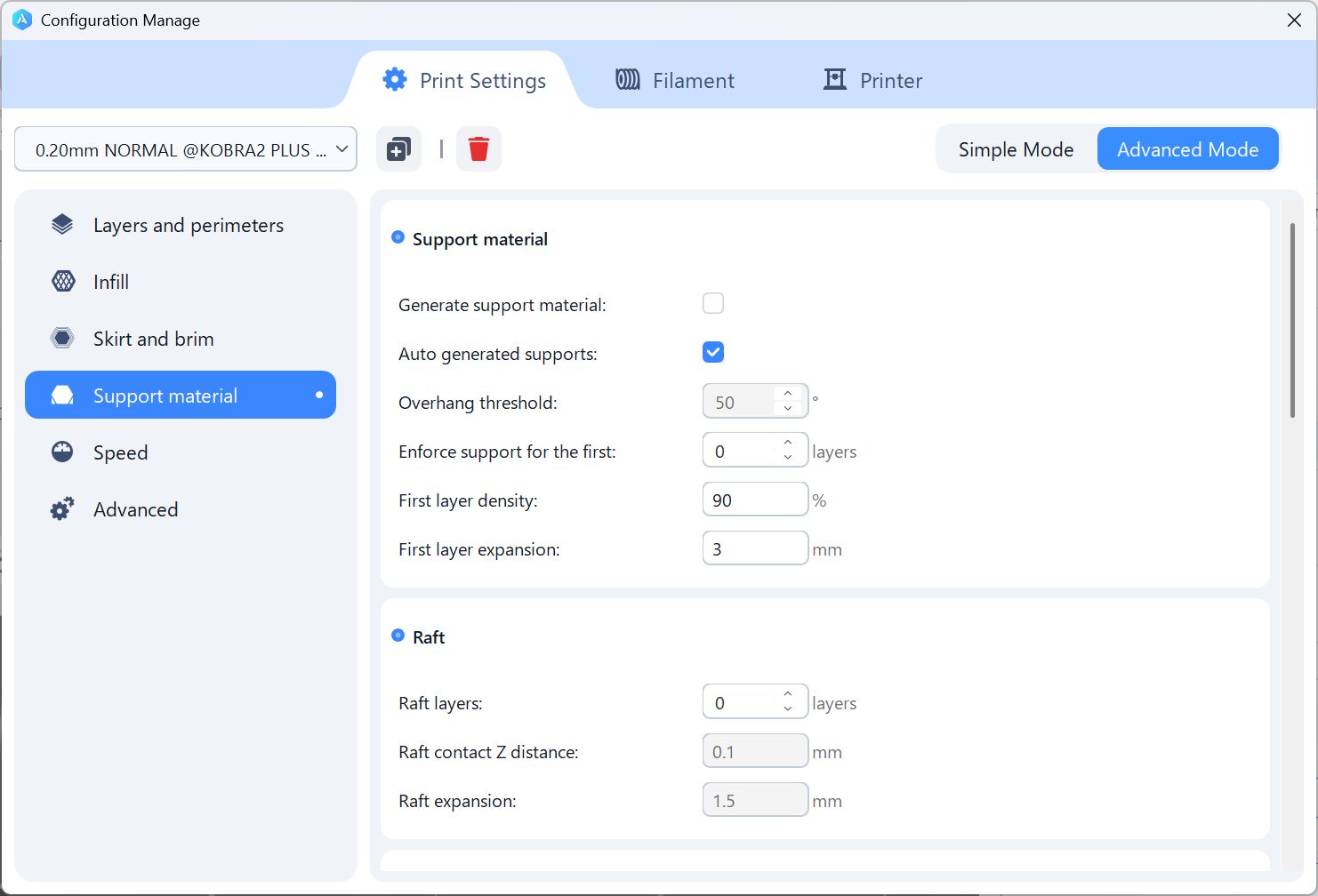
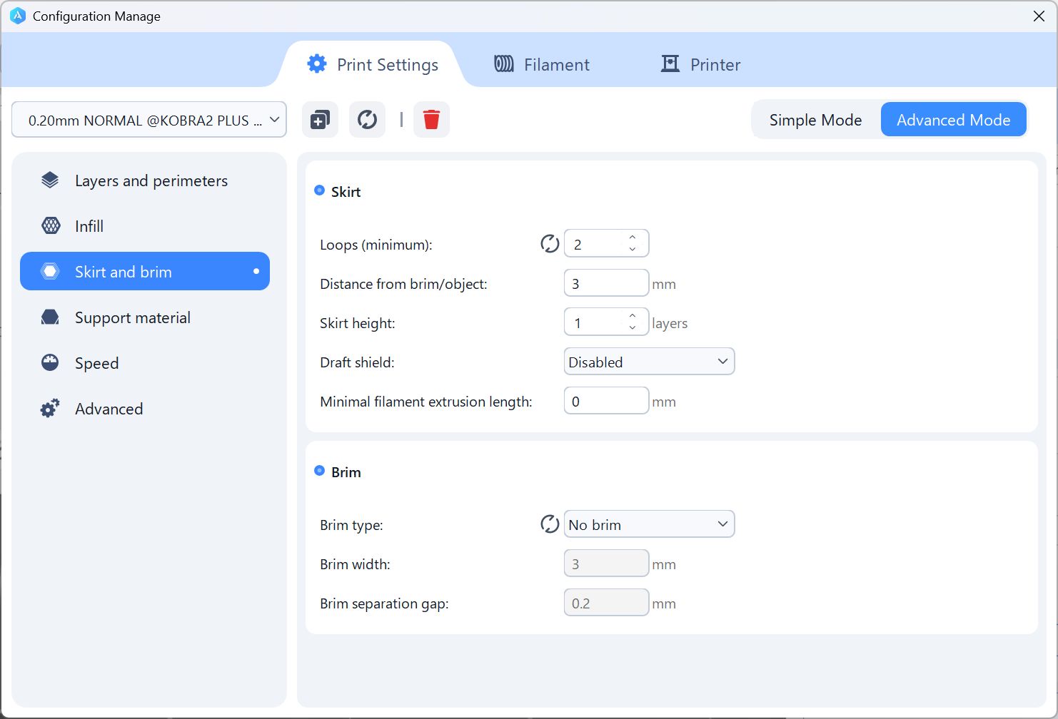
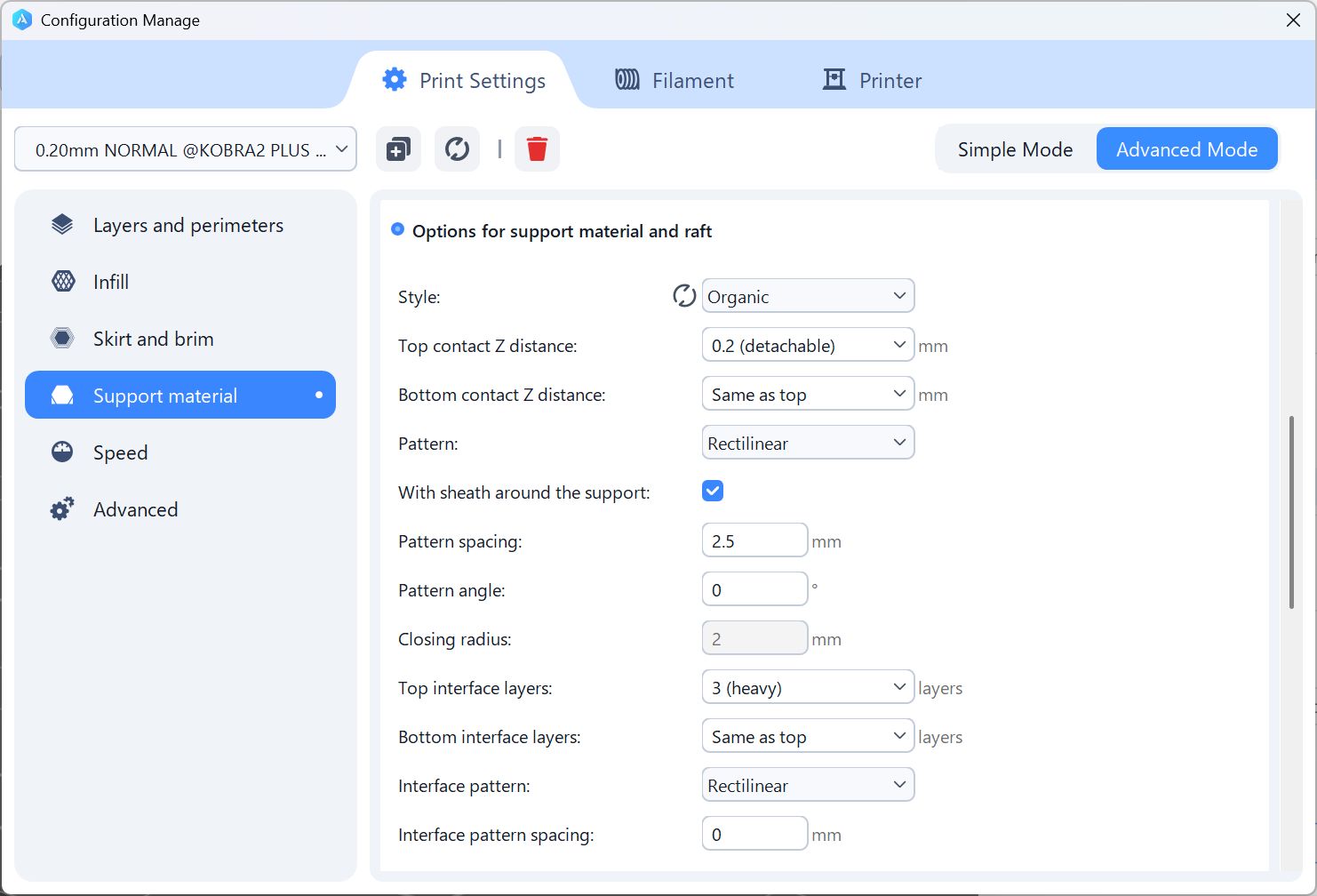
For Case part, I set the support as Organic(= tree shape, easy to take off)
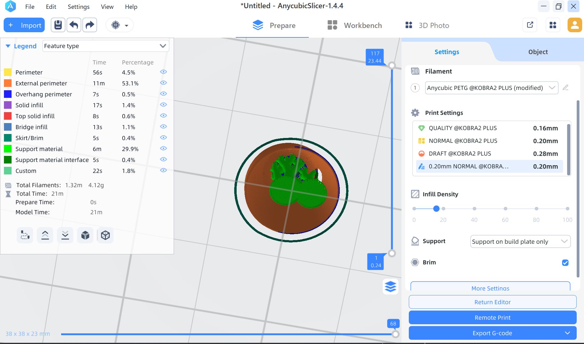
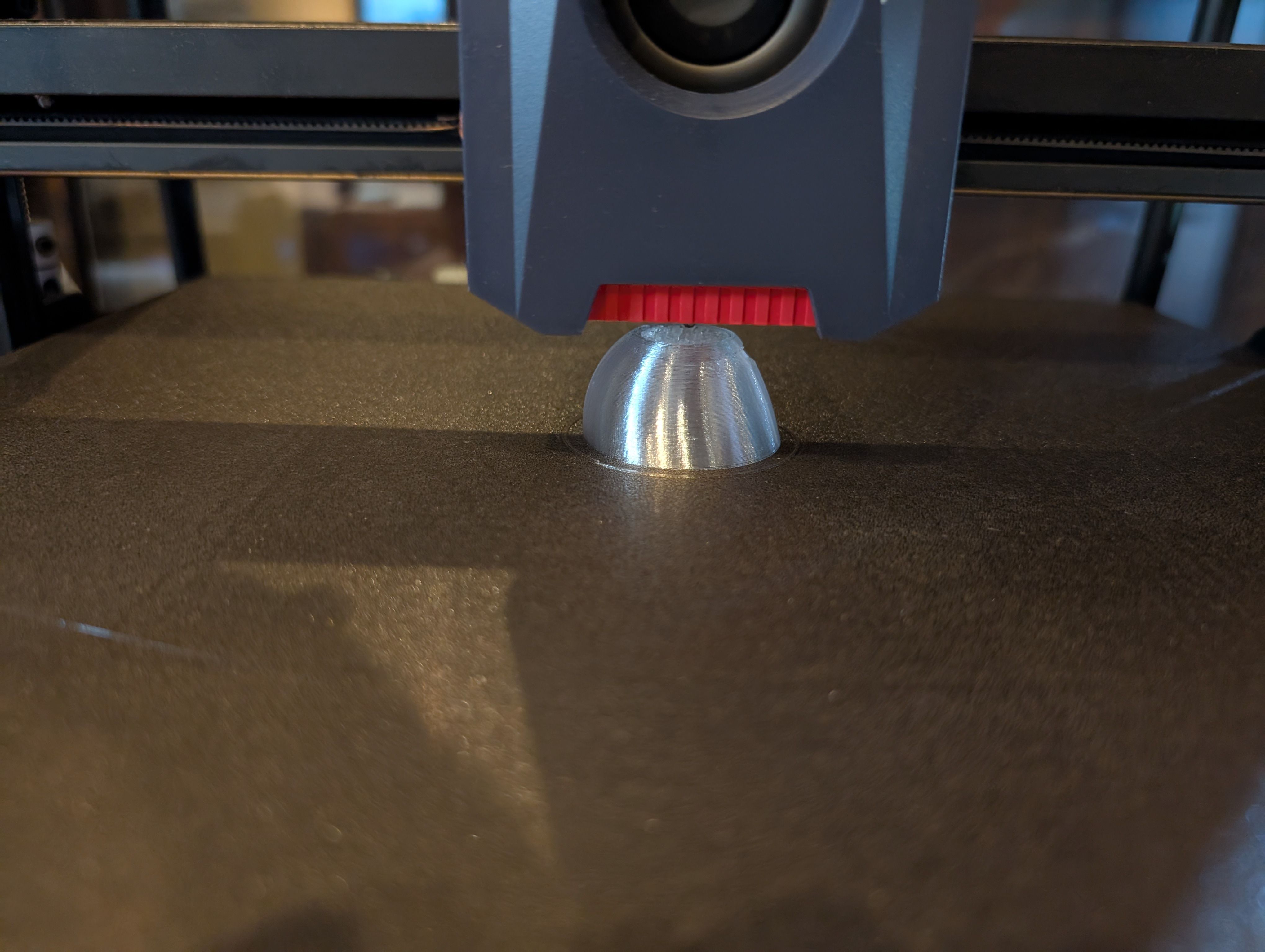
Print it out.
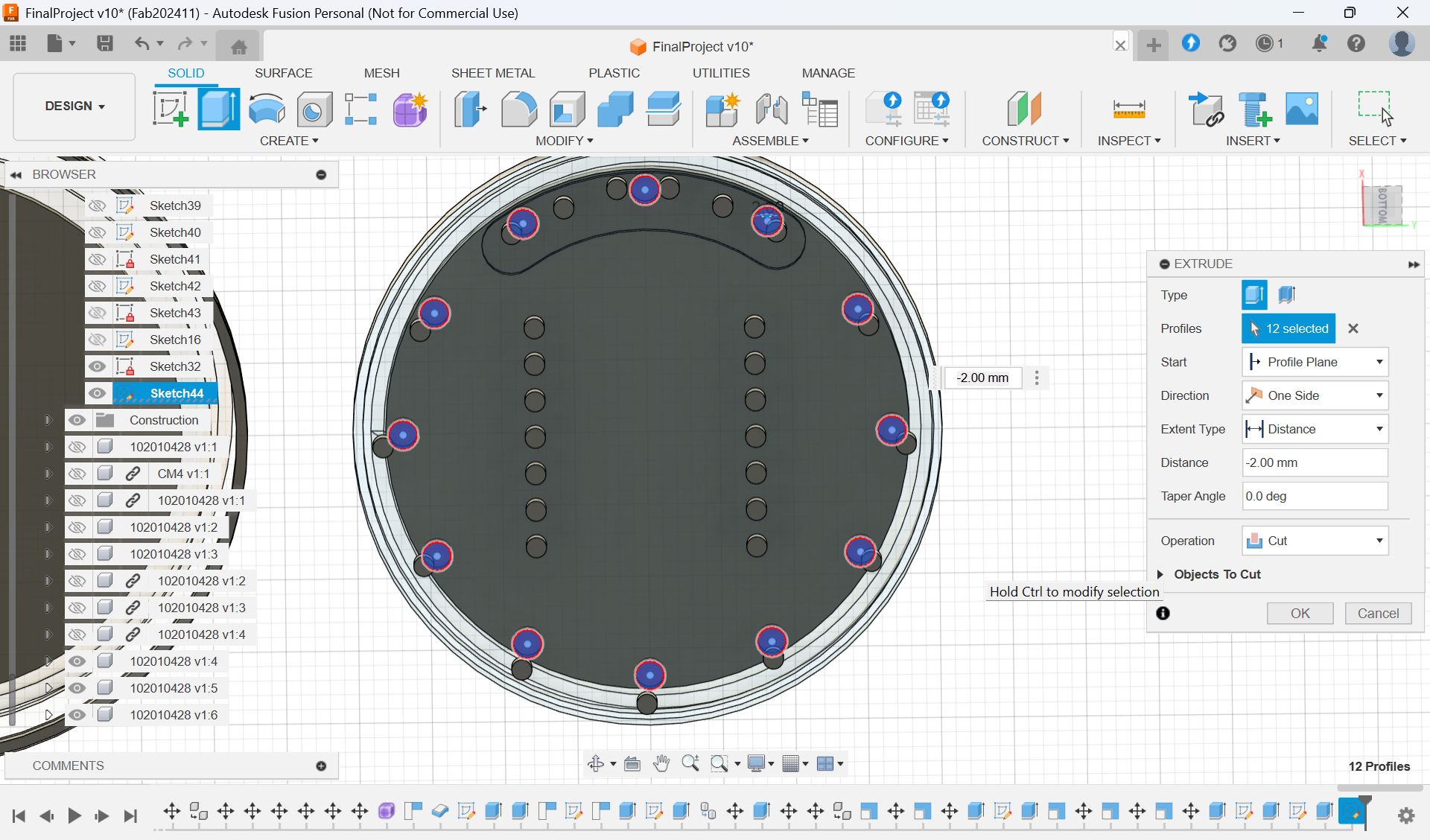
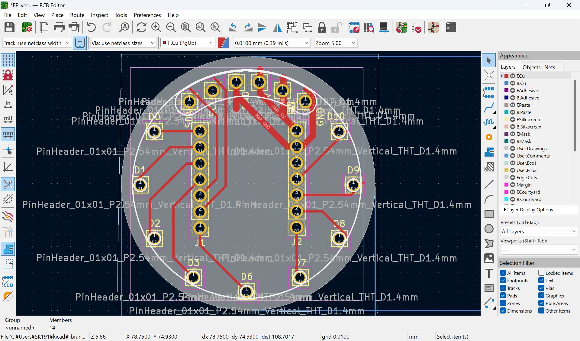
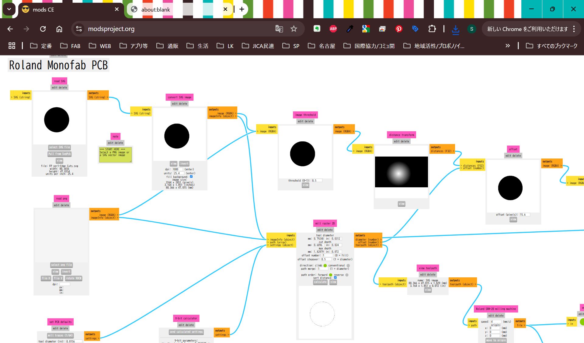
Make PCB fit for the case
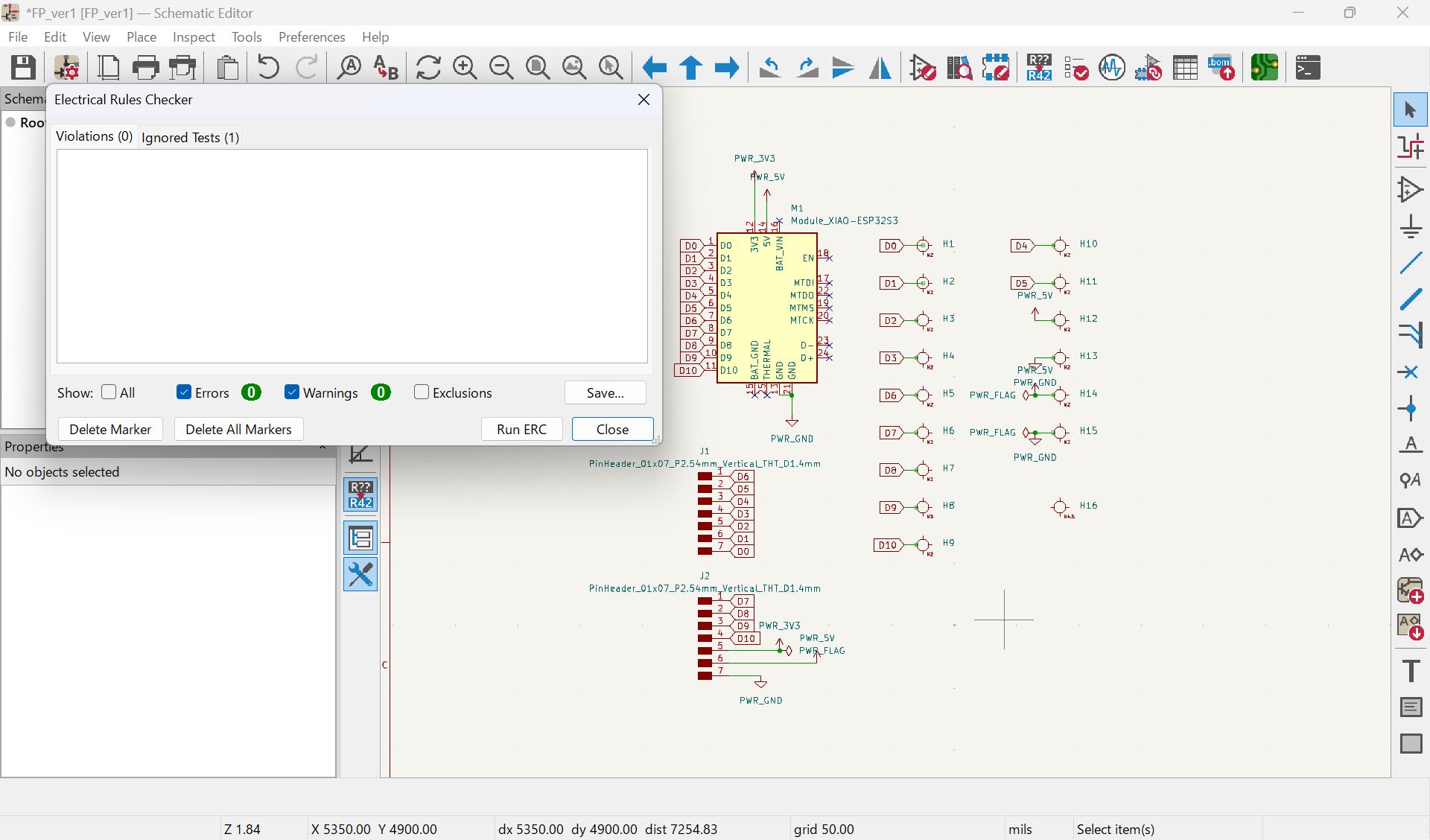
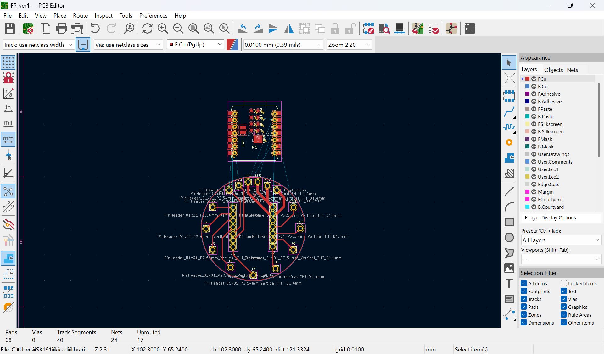
I mistook the pinout, and modified
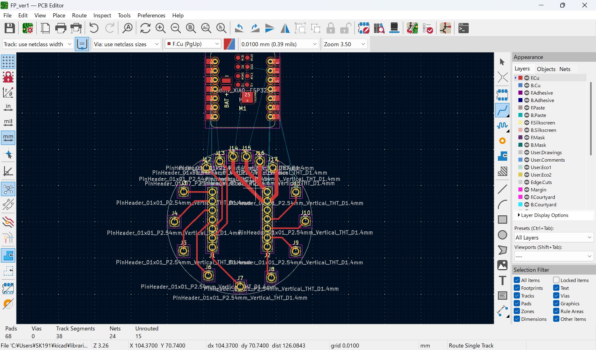

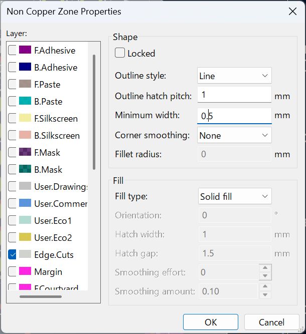
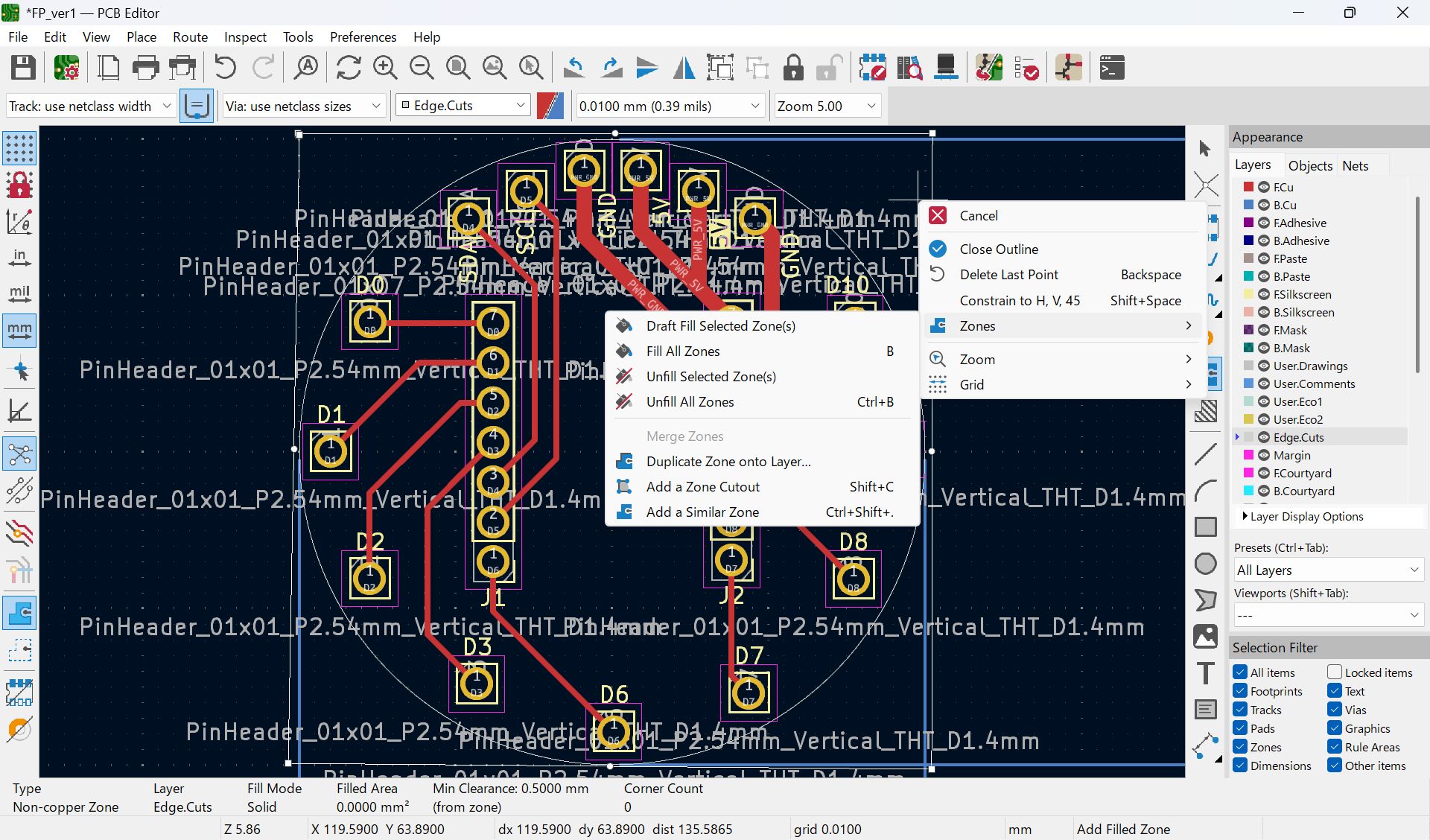
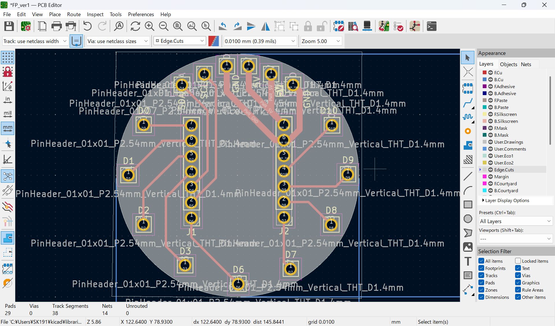
I haven’t documented how to set ‘Fill all zones’, I set as below before select fill all zone
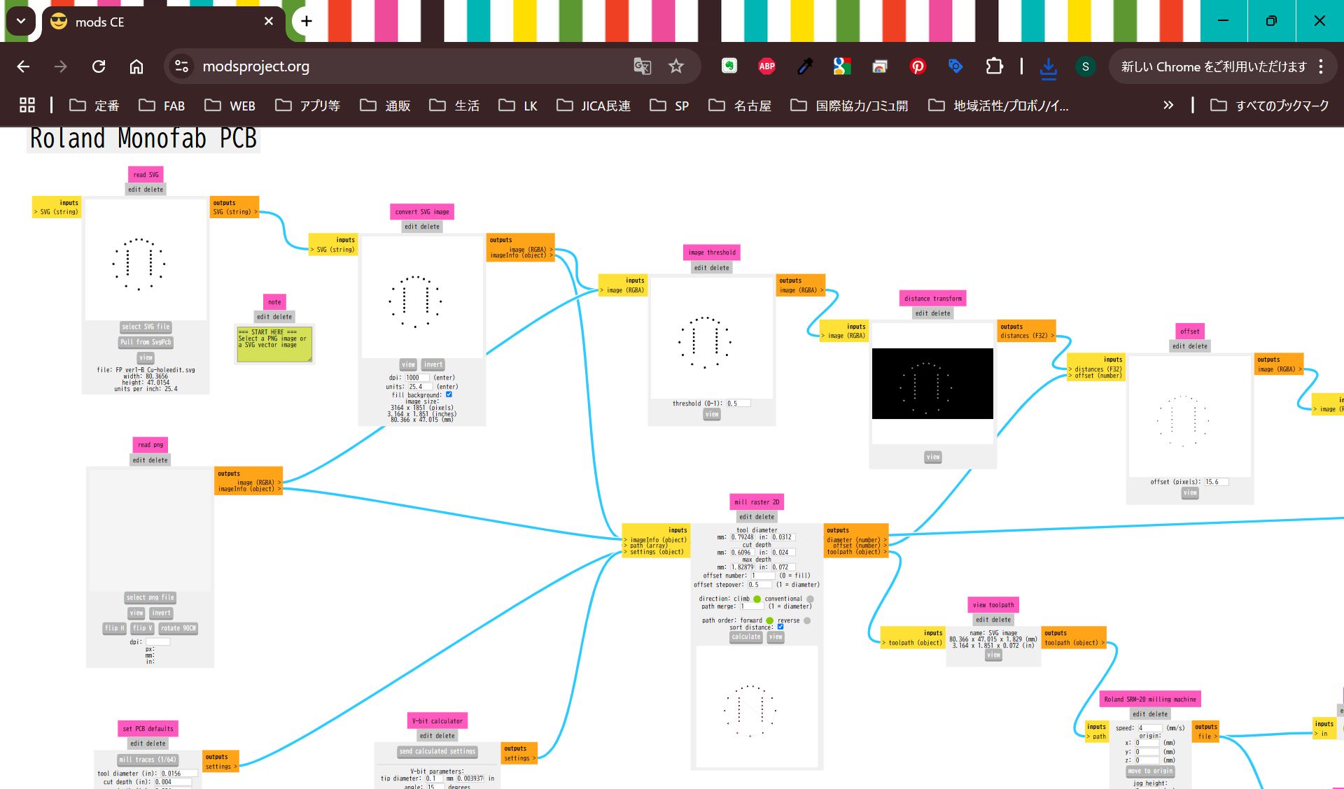
Modify hole cut line file
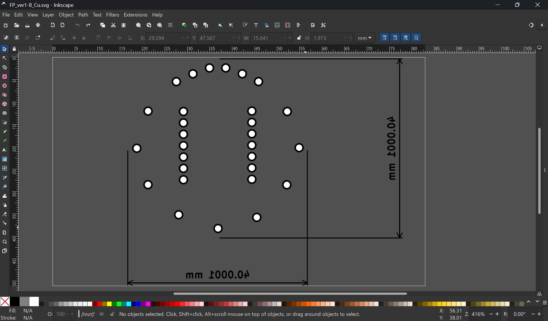
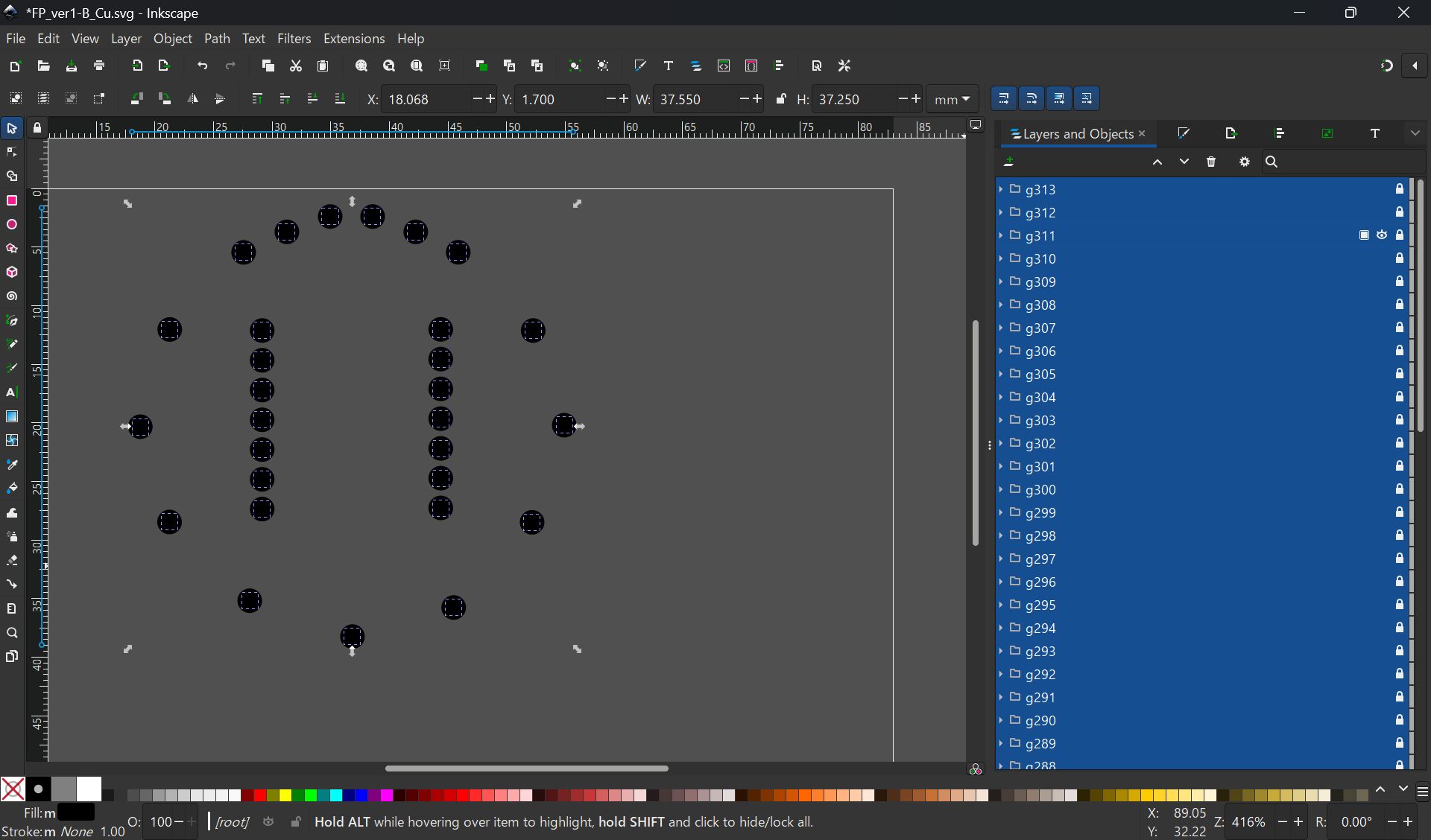
I import svg file from KiCad, but it was difficult to make it fit, so finally, I project the case face and made the svg image from Fusion, and import it in KiCad, and modified design.
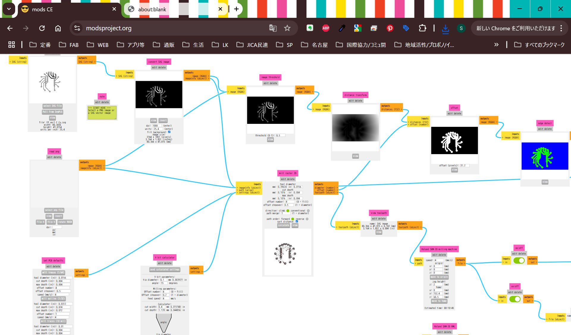
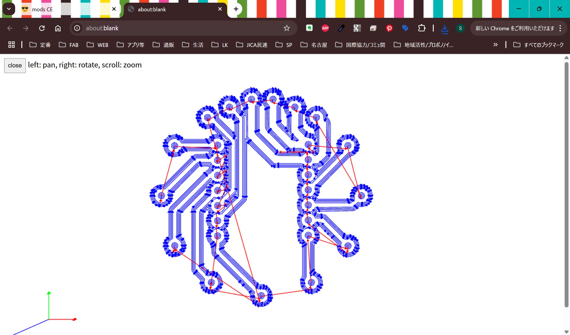
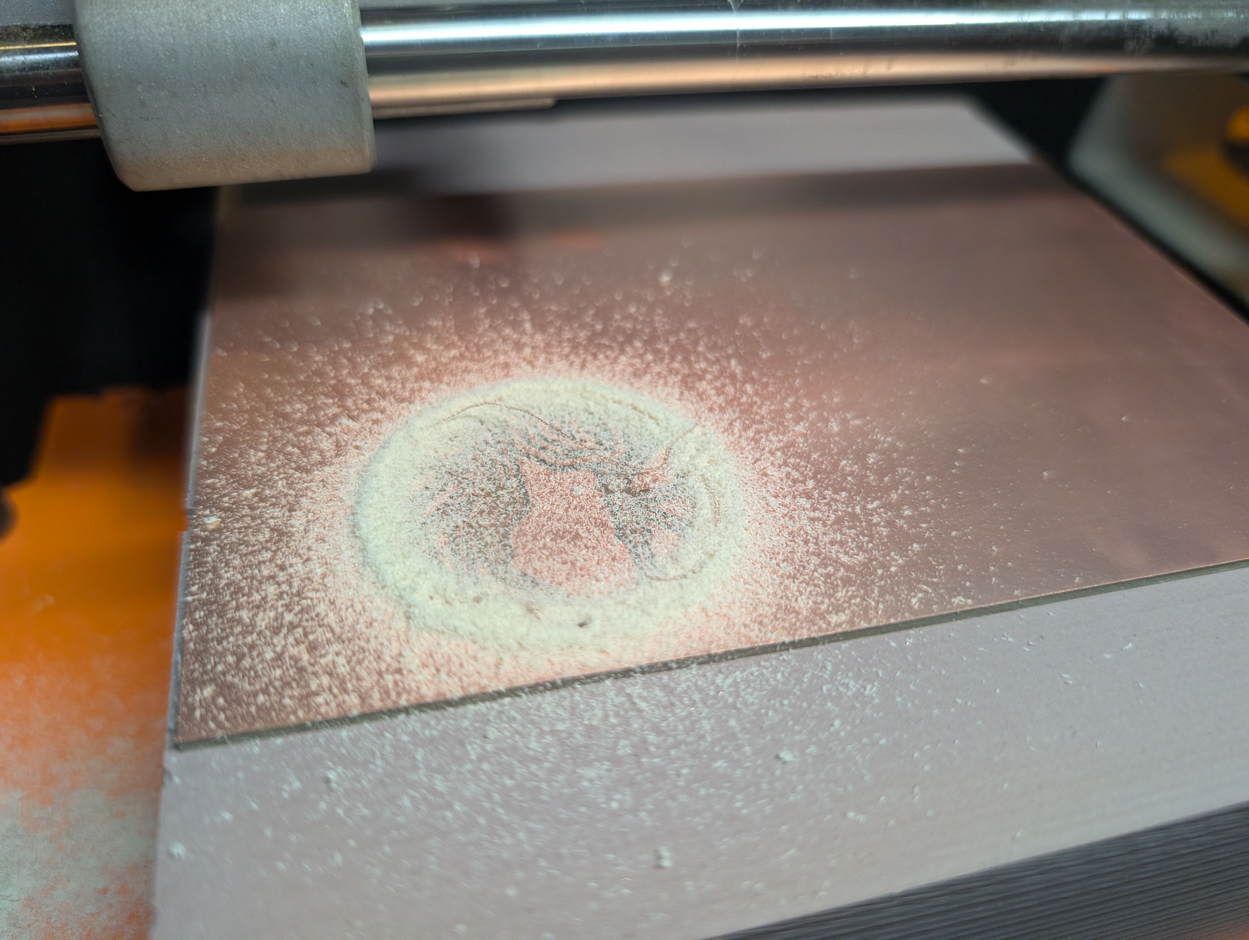
*No invert for hole
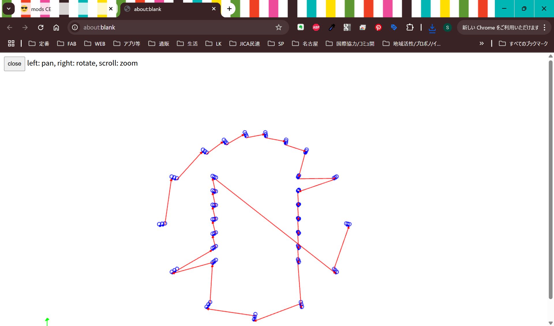
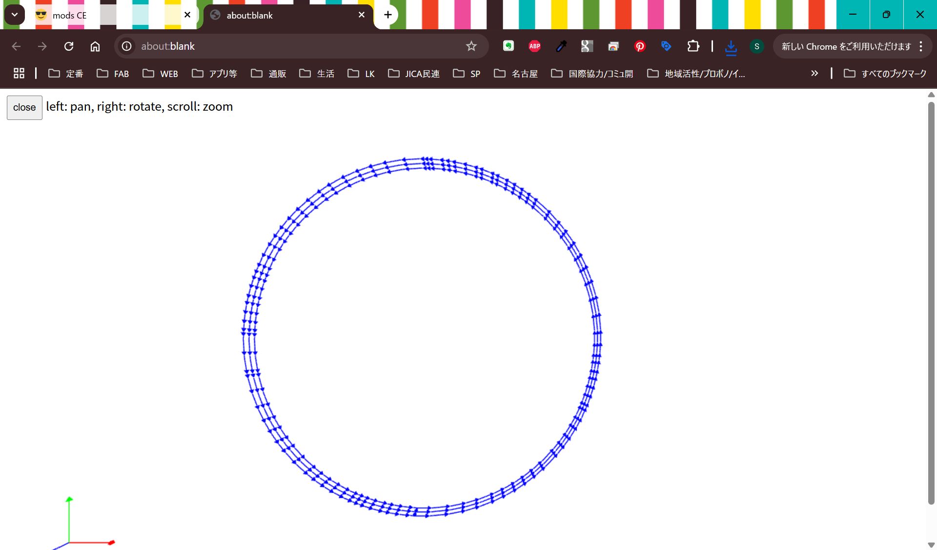
Cut it and assemble.
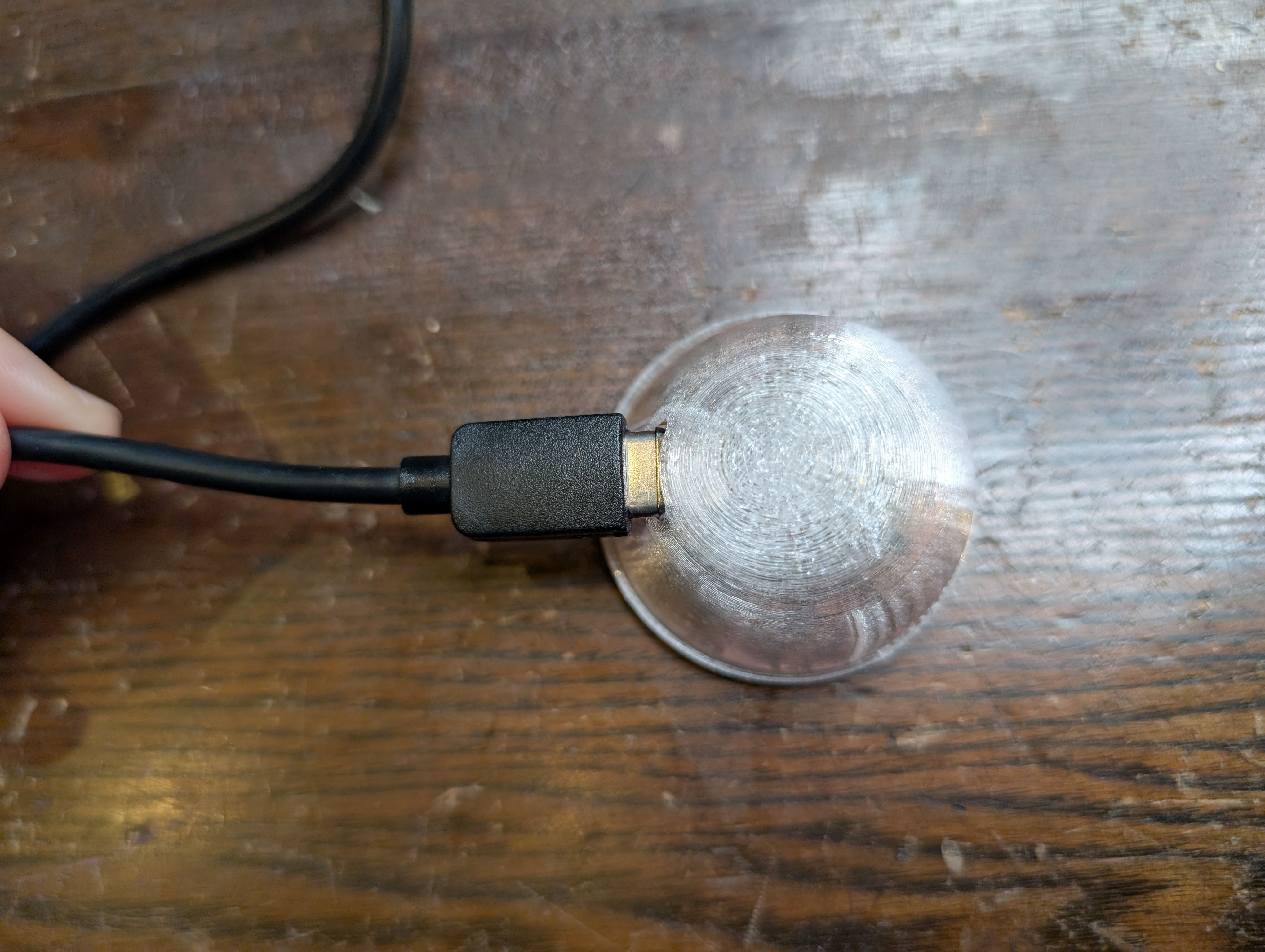
Outcomes
Remaining issues - things to check
Remaining Tasks:
- Final solution for the sensor part
- How do I ground and project the projector to project a little higher (Diagonally, use a mirror, etc.)
- Wiring for the projector part (inside the base) and the connection part