Final Project

This is the page for describe my final project: Cultural Memory Globe

About 
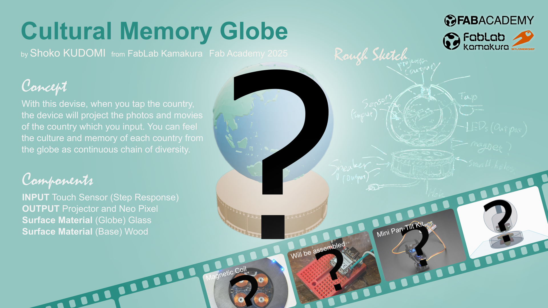
My Final Project: Cultural Memory Globe

I love traveling. Why? It is because I like to feel the difference of each unique local nature, culture, and people’s lives of each places. These days we can learn differences between different areas of the earth through the internet or SNS, and feels as if we know about it. However, once I visit the place actually, I really understand what is the place like. Through the final project, I would like to create something make you feel uniqueness of each places and cultural graduation of the world. This would be also nice to record my travel memories with actual feeling.

First Sketch

This is my first sketch of the device.


Features

Basically, this device consists of 2 parts: globe and base. When you choose the country on the globe, the device will project the photos/videos of the country, and also, if possible, it shows the temperature of the place with LEDs or heat.

Basic Function

  • INPUT : Tap a country you want
  • OUTPUT :project the photos/videos of the country/change temperature of the device
  • Surface Material (Globe): Not decided(Glass or metal?)
  • Surface Material (Base): Wood

Planning

Then, I made plan for each week (Just in case my job get too much busy).
# M D Class Plan
1 Jan 22 principles and practices, presentations, introductionsproject management Finish my rough sketch
2 29 computer-aided design Model the device
3 Feb 05 computer-controlled cutting Try to make/think about base part
4 12 embedded programming Try to program the function of tap and glow
5 19 3D scanning and printing Try to make inside of the device / print out glove part
6 26 electronics design design the electronics of the device
7 Mar 05 computer-controlled machining - (Make something big)
8 12 electronics production Cut/print the electronics of the device
9 19 input devices Try to make sensor parts
10 26 output devices Try to make speaker/projector parts
11 Apr 02 networking and communications Try to make signals between globe part and base part
12 09 mechanical designmachine design - (group assignment week)
13 23 molding and casting Try to create a mold for casting the globe
14 30 interface and application programming Try to make app which can add/manage photos
15 May 07 system integration Try to make it integrated
16 14 wildcard week Try to cast the globe part with (possibly) glass?
17 21 applications and implications,project development -
18 28 invention, intellectual property, and income -
19 Jun 06 weekly assignments deadline -
09- final project presentations -

Week 2 : 3D Modeling

In week 2, I tried modeling of the device. First, I mage a rough sketch for modeling.


Then, I model it as follows:

  1. Think and design overall structure of the device with Tinker Cad
  2. Modeling for ‘Globe’ part with Blender
  3. Modeling for ‘Base’ part with Fusion
  4. Combine Globe and Base in Blender

Tinker Cad
‘Globe’ part modeling with Blender
‘Base’ part modeling with Fusion
Combine Globe and Base in Blender

For the details, please see Week2 Computer-Aided Design page.

Week 6 : Consider the configuration of the processor and peripherals

This week I searched about possible processors/microcontroller and configurations.

Board ESP32 Seeed Studio XIAO ESP32S3 Seeed Studio Xiao ESP32C3 Seeed Studio XIAO ESP32C6 Arduino Nano Raspberry Pi Zero W (Projection)
Microcomputer ESP32 ESP32S3 ESP32C3 ESP32C6 ATmega328P RP3A0
Datasheet esp32_datasheet_en.pdf esp32-s3_datasheet.pdf esp32-c3_datasheet_en.pdf esp32-c6_datasheet_en.pdf A000005-datasheet.pdf https://www.raspberrypi.com/products/raspberry-pi-zero-w/

Final configuration plan at this point

During the Lab session, I was advised that if touch + projection is required, the following configuration example would be good. As expected, a Raspberry Pi is required instead of a microcontroller to project videos.

Application Microcontroller Input Output
Touch input detection xiao
(RP2040 or ESP32)
step response
(need to decide numbers)
-
Projection Raspberry Pi - projector
(need to be chosen)

Week 9 : Consider how to input

For this week, I try out various types of touch sensors.

  1. Processor (xiao ESP32S3)
  2. 1 pin with Resistor (xiao RP2040)
  3. 2 pin (xiao RP2040)
  4. MPR121 (xiao ESP32C3)
Results

The results for xiao ESP32S3 are as follows:

Pin Figure
T1 28600
T2 27500
T3 32000
T7 30700
T8 29100

The results for 1 pin with Resistor are as follows:
Horizontal: Length of wire × Vertical: Size of resistor
*I couldn't figure out the N/A part very well.

No wire(board direct) 25cm(thick) 25cm(0.2㎜²)
1 100k 7500-15000 500 200
2 100k ~15000 1000 200
3 1M N/A N/A N/A
4 1M ~10000 6-700 400
5 2M 8000~20000 N/A 500

For the details, please see Week9 Input Device page.

Week 10 : LED for lightning

For this week, I try to use Neopixels to light up the sphere.
First I connected it to the S3 and tested it.
It worked fine at first, but then it stopped working, so I used the C3 to test different ways of lighting it up.
I also thought about how to display it.

1000012759.jpg
1000012758.jpg
1000012765.jpg

For the details, please see Week10 Output Device page.

Week 11 : Try wifi connection / communicate with Raspberry Pi

For this week, I tried some communication especially for FP:
1. Use xiao ESP32C3 as WiFi server
2. Communicate with Raspberry Pi with I2C
3. Projection test for Raspberry

NeoPixel - On/off with browser

I tried to turn on and off NeoPixel from the browser. I made it from ”SimpleWiFiServer” test code and the code I made last week for NeoPixel.
Code is on week 11 page

It worked!

1000012930.jpg

However, the NeoPixel were lighting up a little strangely. This will need to be adjusted if I use it finally.

2.I2C - Raspberry Pi(Master)-ESP32C3(Slave)

In the Final Project, I want to use a Raspberry Pi for projection, so I tried communicating with Raspberry Pi.
Load the slave code into Xiao. I used the code provided by Maki-san. (code is on week 11 page)
Check the connection with “i2c detect” command

image.jpg

Make master code into python (helped by Tsuchiya-san). The behavior differed slightly depending on the library, and it was difficult to get it to respond properly, but after adjusting various things, I was able to get it to work well with the following code.

image.jpg
image.jpg
1000013015.jpg

Testing video processing capabilities by version

I sent video data to Raspberry Pi and did a playback test.
Raspberry Pi Zero → Not smooth
Raspberry Pi 3 → Somewhat not smooth
Raspberry Pi 4 → OK
Raspberry Pi 5 → Super smooth

1000012982.jpg

*Set up for Raspberry Pi

I worked on these with the help of Tsuchiya-san

Installing the Raspberry Pi OS
Download OS from here: https://www.raspberrypi.com/software/

Install OS to SD card

Reference:
https://pages.switch-science.com/Pi400GS/3_installing_raspberry_pi_os.html
https://raspi-school.com/getting-started-with-raspberrypi/

Settings: Choose OS (filtered by device), and select SD card as strage

image.jpg

How to control it remotely
To connect remotely, the following Wi-Fi settings are required during the OS installation phase.

  • set host name, user name and password
  • set Wi-Fi
  • Enable SSH
image.jpg
image.jpg

Remotely connect to the Raspberry Pi from the terminal (you can connect with a username and IP address)
VNC settings (allow remote access)
Open the VNC viewer and enter the IP address to access
*Do not disconnect the WiFi connection when you want to connect remotely!!!
You can also add new WiFi

*You should download VNC viewer for remote desktop:

image.jpg
image.jpg

Open VNC Viewer, and set Username and pass

image.jpg
image.jpg

Choose address, and you can operate Raspberry Pi remotely

image.jpg

*Above is GUI, but you can also control it with CUI
I used Tera Term
https://teratermproject.github.io/
https://github.com/TeraTermProject/teraterm/releases

Choose TCP/IP, set Host as Raspberry Pi address, select SSH and connect

image.jpg
image.jpg

How to set up WiFi
  • Create “wpa_supplicant.conf” file.
  • Load the created file onto the SD card with the OS.
  • Connections are made in order from the top. List the primary at the top.
  • The file will disappear after being loaded once. It is loaded into the system.
  • When new connection destinations are added, the file will be recreated and loaded again.

Reference: https://qiita.com/otibosi/items/115d4b85d386fa670a58

image.jpg
image.jpg

How to send files

Put files into Raspberry Pi via SFTP connection

Install FTP software (winSCP)
https://forest.watch.impress.co.jp/library/software/winscp/download_10950.html

login and connect to the address with SFTP
You can now send and receive files between your PC and Raspberry Pi.

image.jpg

How to enable I2C

Open Raspberry Pi Config and enable I2c.

image.jpg

For the details, please see Week11 Networking and Communications page.

Midterm

System Diagram

FP-diagram.jpg

Task List

  • 0. Choose Country for 1st spiral
  • 1-1. Try other sensors suggested by Neil
  • 1-2. Choose the mechanism
  • 2-1. Make code for sensors
  • 2-2. Find the right sensitivity
  • 2-3. Decide xiao model
  • 3-1. Decide RaspberryPi Model
  • 3-2. Make code for projection
  • 4-1. Choose projector
  • 4-2. Decide how to show the images
  • 5-1. Make Globe parts(Sandblasting?)
  • 5-2. Make Base parts(CNC?)

Schedule for the remaining week

Month 4 5 6
Day 27 28 29 30 1 2 3 4 5 6 7 8 9 10 11 12 13 14 15 16 17 18 19 20 21 22 23 24 25 26 27 28 29 30 31 1 2 3 4 5 6 7 8
Tasks
0. Choose countries (5 countries)
1. Input - Touch
1-0. Re-check how sensors work for multiple touch
1-1. Try other sensors proposed by Neil
1-1-1 Multi-touch
1-1-2 Network
1-1-3. Choose a mechanism
1-2-1. Decide on a xiao model
1-2-2. Write the sensor code (modification of 1-1)
1-3-1. Design the board
1-3-2. Cut the board
1-4. Make a world map
1-4-1. Find data
1-4-2. Cut + Spread
1-5. Find the right sensitivity (5 countries)
2. Output - Projection
2-0. Decide on a RaspberryPi model
2-1. Write the projection code
2-2. Preparing the projection image
2-3. Selecting a projector
2-4. Making the base parts (CNC?)
2-4-1. Design
2-4-2. Cutting and assembly
2-5. Deciding how to display the image
3. Integration
3-1. Making the support parts
3-2-1. Incorporating NeoPixcel (Optional)
3-2-2. Creating the NeoPixcel code (Optional)
3-3-1. Considering where to place buttons, etc.
3-3-2. Dealing with the codes
4. Preparing presentation materials
4-1. Video
4-1-1. Shooting
4-1-2. Editing
4-2. Slide image

Week 13 : Base for the glass - casting

For this week, I try to make base parts for the glass globe.
*My first plan was float the globe, but it seems no time to do it for 1st spiral…So this new part is needed.

Modeling - Fusion

I scaled the glass and decide the number
Parameter for final model

image.jpg

Check the cross section

image.jpg

I wanted to add a hole for cables.
Add hole with “Slot“ form Sketch menu and extrude it.

image.jpg
image.jpg

Since the wax is smaller than the model size, I made the half cut mold.
To make it divided in the center, use the “Center of mass”.

image.jpg

This is the final model for 1st half.

image.jpg

Path

This time I alse chosed 3.18 square mill.
Setting for roughing
Scan Lines = X + Y
XY speed = 20 mm/sec

Setting for Finishing
Contour Lines : Up out
XY speed = 15 mm/sec

To will without leaving any edges, I have to delete margin.
I set margin bottom = 0mm from Modeling Form menu.

1000013739.jpg

Check time from “Preview Cutting” menu
Time for roughing: 2:53
Time for finishing: 1:37

To set tool, I have to check the depth of workspace, and height of wax, and calculate
depth of workspace : 31mm
(depth of design: 30mm)
height of wax: 37mm
→tool length should be between 31-37

1000013745.jpg
1000013746.jpg

Start cutting.
Roughing goes well.

1000013758.jpg
1000013761.jpg
1000013762.jpg

Finisinng

1000013771.jpg

However, while finishing, the wall broken…(for make hole)
It seems the width is too thin.
Since the mill blades go in from the same direction every time, I think too much pressure was being applied in that direction only.

1000013774.jpg
1000013782.jpg

Result for 1st half mold

1000013786.jpg

Make 2nd half mold
After 1st half mold, since the hole is too thin to cut out, I made the hole bigger and made 2nd half mold.

image.jpg
image.jpg

Setting for roughing

1000013789.jpg
1000013791.jpg

Setting for finishing

1000013792.jpg
1000013794.jpg

Time for roughing: 2:49
Time for finishing: 1:36

1000013795.jpg

Roughing

1000013800.jpg
1000013802.jpg

Finishing

1000013803.jpg
1000013809.jpg

*A large amount of waste was generated

It fits nicely

1000013812.jpg

The broken part was fixed with glue.

1000013813.jpg

The 2 parts were also fixed together with glue and clamp.

1000013817.jpg

Casting

I used Ecoflex 00-30. Part A : Part B = 1 : 1 = 120g : 120g

1000013821.jpg
1000013822.jpg

Mix them well and put to the mold

1000013823.jpg
1000013826.jpg
1000013824.jpg

Result

It fit well with the glass!

1000013842.jpg
1000013851.jpg
1000013856.jpg
1000013874.jpg
1000013880.jpg

For the details, please see Week13 Molding and Casting page.