#4 Embedded Programming
This week I learned how to choose processor and develop it.
Assignment
Group assignment:
Individual assignment:
- Browse through the datasheet for your microcontroller
- Write a program for a microcontroller, and simulate its operation, to interact (with local input &/or output devices) and communicate (with remote wired or wireless connection)
Outcomes
What did I do this week: 1. Group Assignment
The group assignment page - week04
Demonstrate and compare the toolchains and development workflows for available embedded architectures
There are four major processor families(the major boards that use them):
- AVR Family (for Arduino, etc.)
- ARM Family (for Raspberry Pi, etc.)
- MIPS Family (for ESP series)
- RISK-V Family
This time, we decided to compare
boards from the AVR, SRM, and ESP families.
AVR → Arduino Uno(AtMega328P),
Arduino Pro Micro(AtMega32U4)
ARM → Xiao RP2040(RP2040)
ESP →M5StackCore(Espressif
ESP32)
We used the Arduino IDE to compare
toolchains.
Toolchains differ largely based on the following factors:
- Chip
- Language
- IDE
For details, please see the group page: The group assignment page - week04
What did I do this week: 2. Individual assignment
Browse through the datasheet for your microcontroller
Of the four major families mentioned above, I compared the datasheets of the RP2040 from the ARM Family and the ESP32 from the MIPS Family. I have summarized the points that seems particularly important below:
| RP2040 | ESP32 | ESP32-C3 | Meaning of the item | |
|---|---|---|---|---|
| Source | rp2040-datasheet.pdf | esp32_datasheet_en.pdf | esp32-c3_datasheet_en.pdf | - |
| CPU | Dual ARM Cortex-M0+ | Xtensa® single-/dual-core 32-bit LX6 microprocessor( | 32-bit RISC-V single-core processor | |
| Cores | 2 Cores | 2 Cores | 1 Core | |
| Frequency | 133MHz | 240 MHz | up to 160 MHz | Processing speed per second |
| Memory(SRAM) | 264kB on-chip SRAM | 520 KB SRAM | 400 KB SRAM (16 KB for cache) |
Processing capacity |
| Memory(Flash) | 16MB (off-chip) | QSPI supports multiple flash/SRAM chips | 0 - 4MB | Memory capacity (rewritable) |
| Clocks | 2 on-chip PLLs to generate USB and core clocks | Internal 8 MHz oscillator with calibration | *ESP32-C3 is unable to operate without an external main crystal clock. | Speed of signals used by the CPU to synchronize processing |
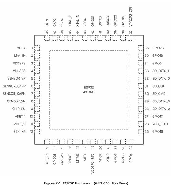
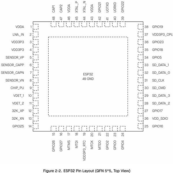
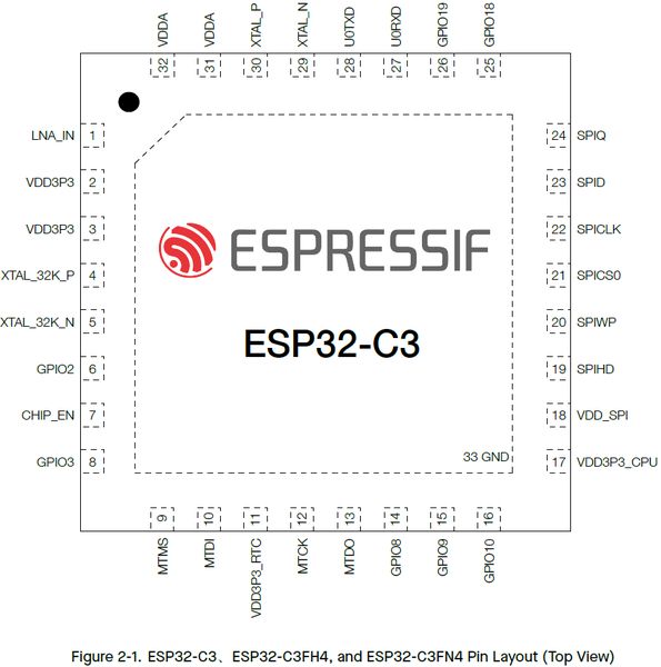
| GPIO pin Nos | 30 | 34 | 22 or 16 | How many external connections are possible |
| Peripherals |
|
|
|
Communication Protocol |
| Wi-Fi | - | 802.11b/g/n 802.11n (2.4 GHz), up to 150 Mbps |
IEEE 802.11b/g/n-compliant Supports 20 MHz, 40 MHz bandwidth in 2.4 GHz band |
|
| Bluetooth® | - | v4.2 | 5 | |
| Pin Locations | 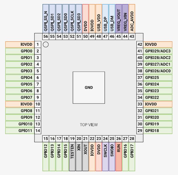 |
  |
  |
|
| Functional Block Diagram | 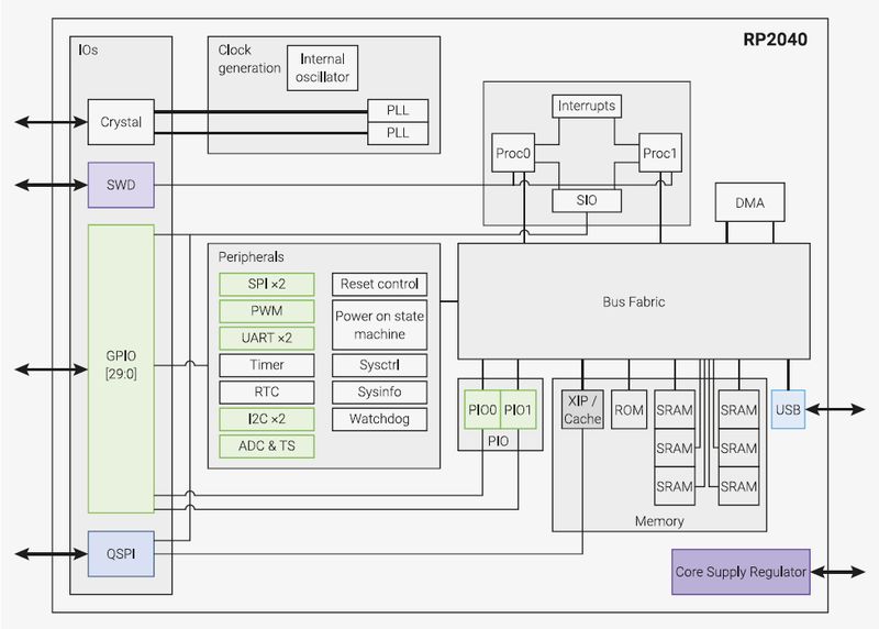 |
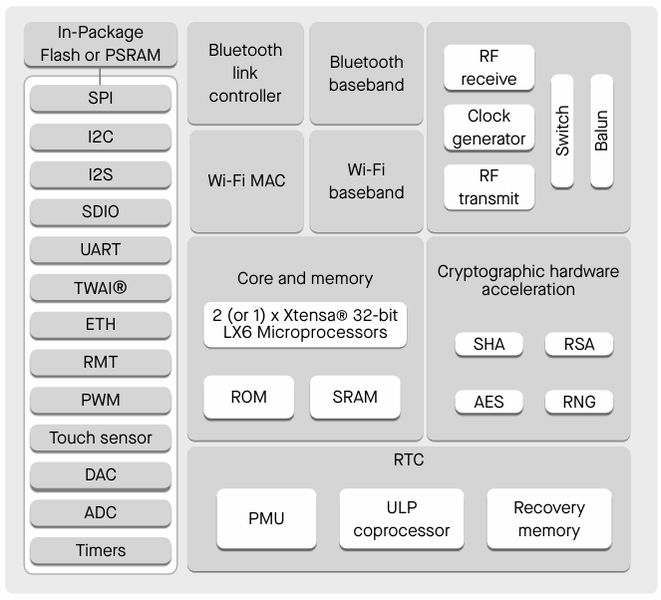 |
 |
Write a program for a microcontroller, and simulate its operation, to interact (with local input &/or output devices) and communicate (with remote wired or wireless connection)
In class, we learned that embedded
programming is done in the following order:
- Choose(purchase) a processor
- Choose a package
- Choose a programming language
- Load into the processor
- Write / develop a program
- Connect peripherals and create a board
As for the processor, since I want to use wireless communication in my final project, it seems better to use ESP series that supports Wi-Fi communication or one that is easy to expand to communicate.
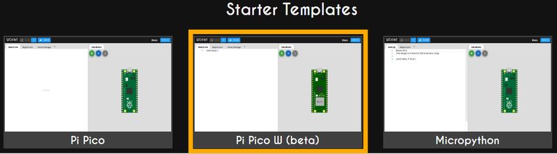
For the simulation, I decided to
try with Wokwi. (https://wokwi.com/)
With
Wokwi, I needed to choose a board. As a board that can use WiFi, the option might be
ESP32, or, if I choose RP2024, Raspberry Pi Pico W(Raspberry Pi Pico with WiFi).
First, I try to start from RP2040 with Raspberry Pi on Simulator with Nagano-san’s
Recommendation. So I chose “Raspberry Pi Pico W” from Wokwi site. (Following
tutorial is done with Nagano-san’s instruction)
1st Trial
We did a Wokwi tutorial in Local session,also with Nagano-san. So, after the session, I followed the same order and try it on the board I chose(Pi Pico W).
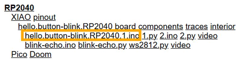
First, I try to trace code from
class page. Since I want to try RP2040 with Arduino(language), I chose “hello.button-blink.RP2040.1.ino”
code. I watched the Wokwi.mp4 tutorial video again, also.
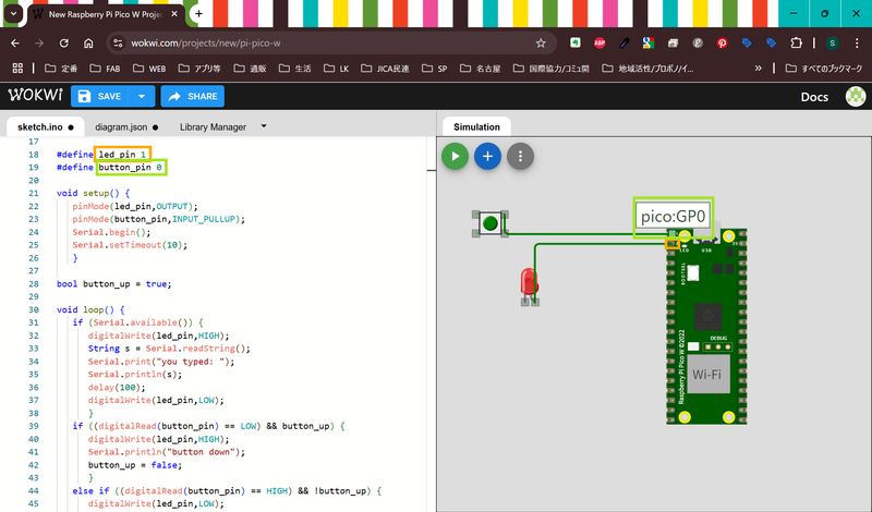
Put the code on the left window of
simulator.
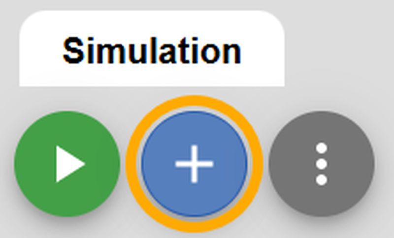
For this code, I need LED and button, so I chose it on the right
window. You can choose parts from “+” button.
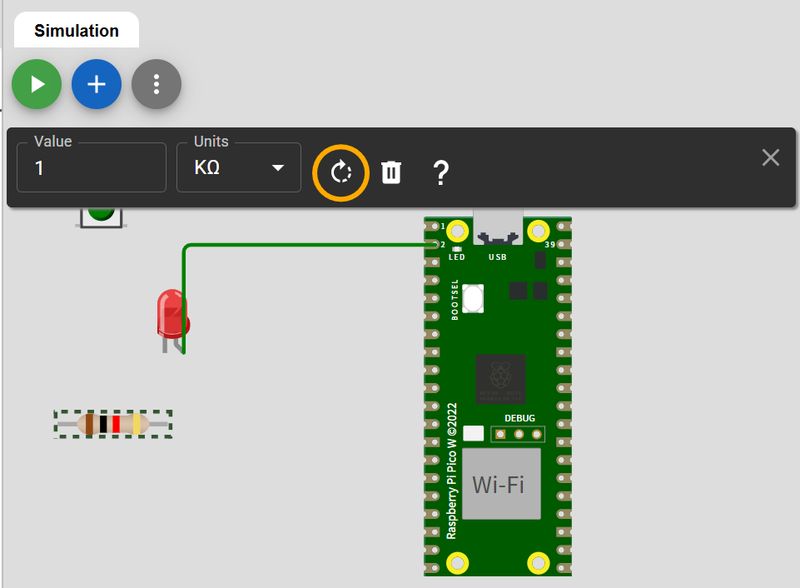
I need to add resister to use LED.
(To rotate the parts, you can do it from the bottun below.)
Then, I tried to run it. Press
green circled “Start the simulation” button.
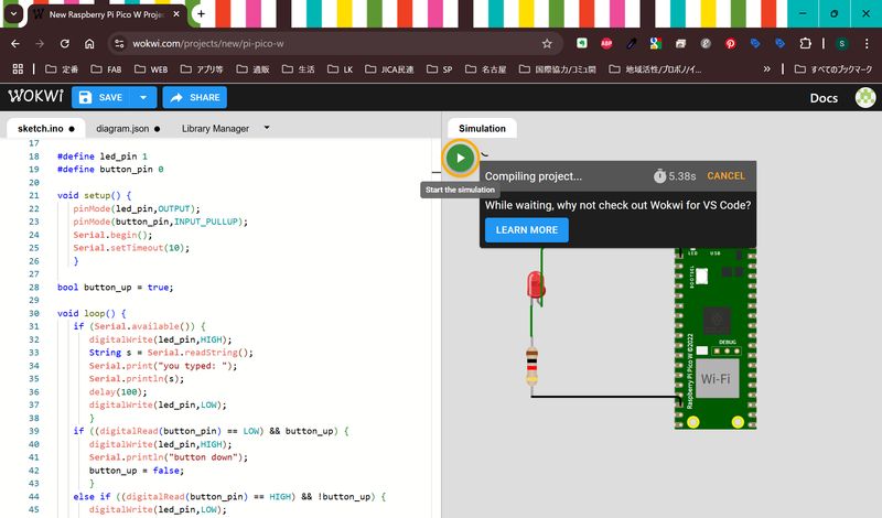
It works, but something went
wrong…text on the serial monitor seems weird.
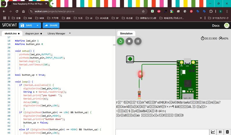
Since it seems “serial” is set for
physical UART interface in Wokwi, I deleted 2 lines below in the diagram.json.(This was also explained in the local session.)
[ "pico:GP0", "$serialMonitor:RX", "", [] ],
[ "pico:GP1", "$serialMonitor:TX", "", [] ],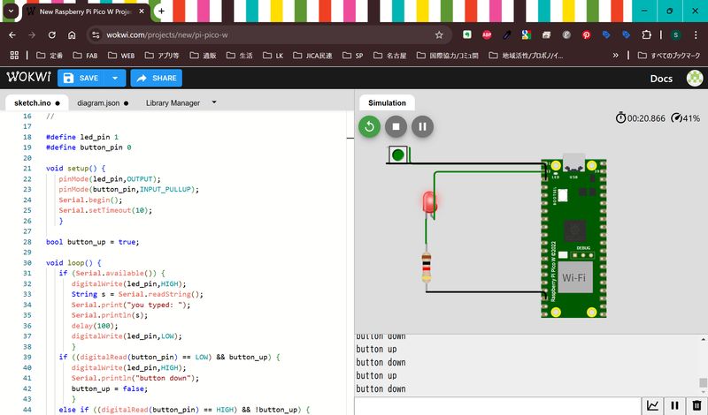
2nd Trial
Then, I tried some variation.
I would like to try to add some
buttons, and depends on the button, change the color of LED.
I decided to try it with
several steps.
- If I press button 1, turn on LED1, press button 2, turn on LED2, press button 3 and turn on LED3.
- If I enter 1, turn on LED1, if I enter 2, turn on LED2…
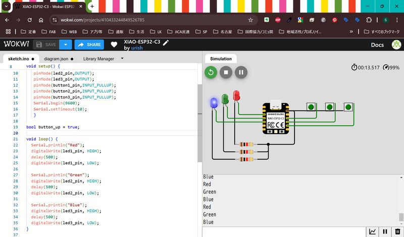
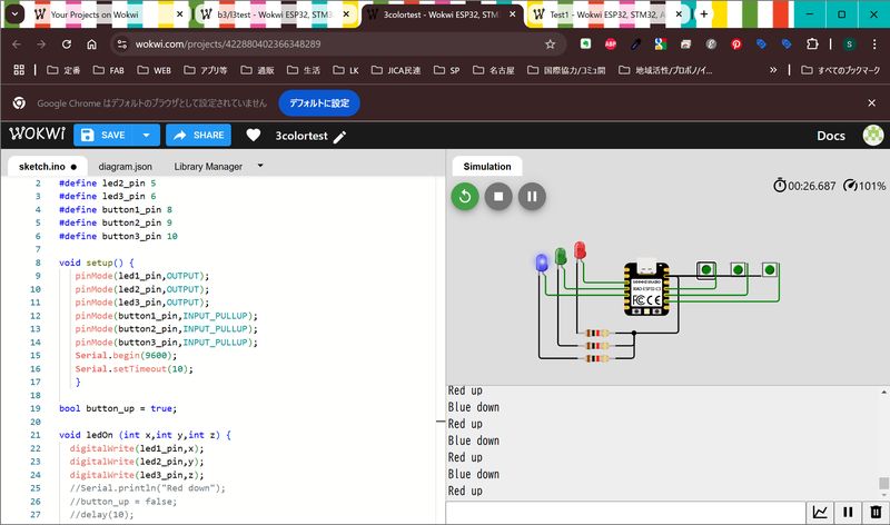
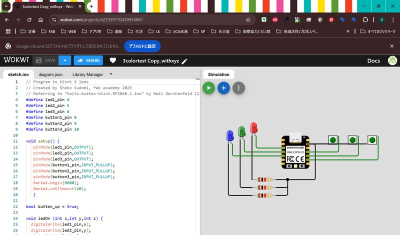
I found the 3color LED source for
ESP32 simulator in Wokwi. So, I arranged it.
↓ Original source image
However, something went wrong(Two colors turn on at the same time...)
The code is as follows:
#define led1_pin 4
#define led1_pin 4
#define led2_pin 5
#define led3_pin 6
#define button1_pin 8
#define button2_pin 9
#define button3_pin 10

void setup() {
   pinMode(led1_pin,OUTPUT);
   pinMode(led2_pin,OUTPUT);
   pinMode(led3_pin,OUTPUT);
   pinMode(button1_pin,INPUT_PULLUP);
   pinMode(button2_pin,INPUT_PULLUP);
   pinMode(button3_pin,INPUT_PULLUP);
   Serial.begin(9600);
   Serial.setTimeout(10);
   }

bool button_up = true;

void loop() {
   if ((digitalRead(button1_pin) == LOW) && button_up) {
      digitalWrite(led1_pin,HIGH);
      Serial.println("Red down");
      button_up = false;
      delay(10);
      }
   if ((digitalRead(button1_pin) == HIGH) && !button_up) {
      digitalWrite(led1_pin,LOW);
      Serial.println("Red up");
      button_up = true;
      delay(10);
      }
   if ((digitalRead(button2_pin) == LOW) && button_up) {
      digitalWrite(led2_pin,HIGH);
      Serial.println("Green down");
      button_up = false;
      delay(10);
      }
   if ((digitalRead(button2_pin) == HIGH) && !button_up) {
      digitalWrite(led2_pin,LOW);
      Serial.println("Green up");
      button_up = true;
      delay(10);
      }
   if ((digitalRead(button3_pin) == LOW) && button_up) {
      digitalWrite(led3_pin,HIGH);
      Serial.println("Blue down");
      button_up = false;
      delay(10);
      }
   else if ((digitalRead(button3_pin) == HIGH) && !button_up) {
      digitalWrite(led3_pin,LOW);
      Serial.println("Blue up");
      button_up = true;
      delay(10);
      }
}
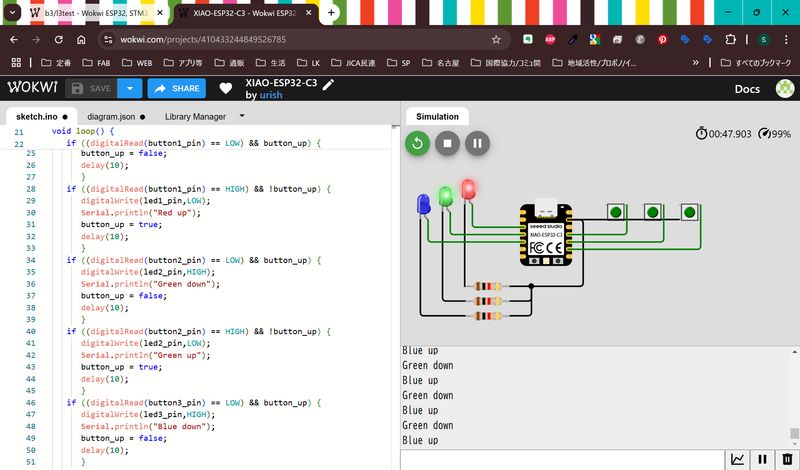
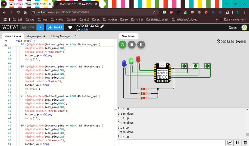
I modified the code as below, and
it works.
The point is to specify the behavior of all the LEDs except the ones you want to operate.
I noticed this because I practiced Arduino language before.
#define led1_pin 4
#define led2_pin 5
#define led3_pin 6
#define button1_pin 8
#define button2_pin 9
#define button3_pin 10

void setup() {
   pinMode(led1_pin,OUTPUT);
   pinMode(led2_pin,OUTPUT);
   pinMode(led3_pin,OUTPUT);
   pinMode(button1_pin,INPUT_PULLUP);
   pinMode(button2_pin,INPUT_PULLUP);
   pinMode(button3_pin,INPUT_PULLUP);
   Serial.begin(9600);
   Serial.setTimeout(10);
   }

bool button_up = true;

void loop() {
   if ((digitalRead(button1_pin) == LOW) && button_up) {
      digitalWrite(led1_pin,HIGH);
      digitalWrite(led2_pin,LOW);
      digitalWrite(led3_pin,LOW);
      Serial.println("Red down");
      button_up = false;
      delay(10);
      }
   if ((digitalRead(button1_pin) == HIGH) && !button_up) {
      digitalWrite(led1_pin,LOW);
      digitalWrite(led2_pin,LOW);
      digitalWrite(led3_pin,LOW);
      Serial.println("Red up");
      button_up = true;
      delay(10);
      }
   if ((digitalRead(button2_pin) == LOW) && button_up) {
      digitalWrite(led1_pin,LOW);
      digitalWrite(led2_pin,HIGH);
      digitalWrite(led3_pin,LOW);
      Serial.println("Green down");
      button_up = false;
      delay(10);
      }
   if ((digitalRead(button2_pin) == HIGH) && !button_up) {
      digitalWrite(led1_pin,LOW);
      digitalWrite(led2_pin,LOW);
      digitalWrite(led3_pin,LOW);
      Serial.println("Green up");
      button_up = true;
      delay(10);
      }
   if ((digitalRead(button3_pin) == LOW) && button_up) {
      digitalWrite(led1_pin,LOW);
      digitalWrite(led2_pin,LOW);
      digitalWrite(led3_pin,HIGH);
      Serial.println("Blue down");
      button_up = false;
      delay(10);
      }
   else if ((digitalRead(button3_pin) == HIGH) && !button_up) {
      digitalWrite(led1_pin,LOW);
      digitalWrite(led2_pin,LOW);
      digitalWrite(led3_pin,LOW);
      Serial.println("Blue up");
      button_up = true;
      delay(10);
      }
}
Try to use functions
Use functions to omit descriptions. This is recommended from Nagano-san.
I was also advised, it would be better to leave lines that are no longer necessary due to the function in comment out form first, and then delete them after checking if it works.
#define led1_pin 4
#define led2_pin 5
#define led3_pin 6
#define button1_pin 8
#define button2_pin 9
#define button3_pin 10

void setup() {
   pinMode(led1_pin,OUTPUT);
   pinMode(led2_pin,OUTPUT);
   pinMode(led3_pin,OUTPUT);
   pinMode(button1_pin,INPUT_PULLUP);
   pinMode(button2_pin,INPUT_PULLUP);
   pinMode(button3_pin,INPUT_PULLUP);
   Serial.begin(9600);
   Serial.setTimeout(10);
   }

bool button_up = true;

void ledOn (int x,int y,int z) {
  digitalWrite(led1_pin,x);
  digitalWrite(led2_pin,y);
  digitalWrite(led3_pin,z);
  //Serial.println("Red down");
  //button_up = false;
  //delay(10);
  }

void loop() {
   if ((digitalRead(button1_pin) == LOW) && button_up) {
      ledOn(1,0,0);
      //digitalWrite(led1_pin,HIGH);
      //digitalWrite(led2_pin,LOW);
      //digitalWrite(led3_pin,LOW);
      Serial.println("Red down");
      button_up = false;
      delay(10);
      }
   if ((digitalRead(button1_pin) == HIGH) && !button_up) {
      ledOn(0,0,0);
      //digitalWrite(led1_pin,LOW);
      //digitalWrite(led2_pin,LOW);
      //digitalWrite(led3_pin,LOW);
      Serial.println("Red up");
      button_up = true;
      delay(10);
      }
   if ((digitalRead(button2_pin) == LOW) && button_up) {
      ledOn(0,1,0);
      //digitalWrite(led1_pin,LOW);
      //digitalWrite(led2_pin,HIGH);
      //digitalWrite(led3_pin,LOW);
      Serial.println("Green down");
      button_up = false;
      delay(10);
      }
   if ((digitalRead(button2_pin) == HIGH) && !button_up) {
      ledOn(0,0,0);
      //digitalWrite(led1_pin,LOW);
      //digitalWrite(led2_pin,LOW);
      //digitalWrite(led3_pin,LOW);
      Serial.println("Green up");
      button_up = true;
      delay(10);
      }
   if ((digitalRead(button3_pin) == LOW) && button_up) {
      ledOn(0,0,1);
      //digitalWrite(led1_pin,LOW);
      //digitalWrite(led2_pin,LOW);
      //digitalWrite(led3_pin,HIGH);
      Serial.println("Blue down");
      button_up = false;
      delay(10);
      }
   else if ((digitalRead(button3_pin) == HIGH) && !button_up) {
      ledOn(0,0,0);
      //digitalWrite(led1_pin,LOW);
      //digitalWrite(led2_pin,LOW);
      //digitalWrite(led3_pin,LOW);
      Serial.println("Blue up");
      button_up = true;
      delay(10);
      }
}
Try to communicate in serial monitor
I tried communication : If I enter
1, turn on LED1, if I enter 2, turn on LED2…
My first source is as below. However, now buttons doesn’t work…
#define led1_pin 1
#define led2_pin 2
#define led3_pin 3
#define button1_pin 0
#define button2_pin 16
#define button3_pin 18
void setup() {
pinMode(led1_pin,OUTPUT);
pinMode(led2_pin,OUTPUT);
pinMode(led3_pin,OUTPUT);
pinMode(button1_pin,INPUT_PULLUP);
pinMode(button2_pin,INPUT_PULLUP);
pinMode(button3_pin,INPUT_PULLUP);
Serial.begin(9600);
Serial.setTimeout(10);
}
bool button_up = true;
void loop() {
if (Serial.available()) {
String s = Serial.readString();
Serial.println(s);
s.trim();
if (s.equals("1")){
digitalWrite(led1_pin,HIGH);
delay(1000);
digitalWrite(led1_pin,LOW);
}
if (s.equals("2")){
digitalWrite(led2_pin,HIGH);
delay(1000);
digitalWrite(led2_pin,LOW);
}
if (s.equals("3")){
digitalWrite(led3_pin,HIGH);
delay(1000);
digitalWrite(led3_pin,LOW);
}
if ((digitalRead(button1_pin) == LOW) && button_up) {
digitalWrite(led1_pin,HIGH);
digitalWrite(led2_pin,LOW);
digitalWrite(led3_pin,LOW);
Serial.println("Red down");
button_up = false;
delay(10);
}
if ((digitalRead(button1_pin) == HIGH) && !button_up) {
digitalWrite(led1_pin,LOW);
digitalWrite(led2_pin,LOW);
digitalWrite(led3_pin,LOW);
Serial.println("Red up");
button_up = true;
delay(10);
}
if ((digitalRead(button2_pin) == LOW) && button_up) {
digitalWrite(led1_pin,LOW);
digitalWrite(led2_pin,HIGH);
digitalWrite(led3_pin,LOW);
Serial.println("Green down");
button_up = false;
delay(10);
}
if ((digitalRead(button2_pin) == HIGH) && !button_up) {
digitalWrite(led1_pin,LOW);
digitalWrite(led2_pin,LOW);
digitalWrite(led3_pin,LOW);
Serial.println("Green up");
button_up = true;
delay(10);
}
if ((digitalRead(button3_pin) == LOW) && button_up) {
digitalWrite(led1_pin,LOW);
digitalWrite(led2_pin,LOW);
digitalWrite(led3_pin,HIGH);
Serial.println("Blue down");
button_up = false;
delay(10);
}
else if ((digitalRead(button3_pin) == HIGH) && !button_up) {
digitalWrite(led1_pin,LOW);
digitalWrite(led2_pin,LOW);
digitalWrite(led3_pin,LOW);
Serial.println("Blue up");
button_up = true;
delay(10);
}
}
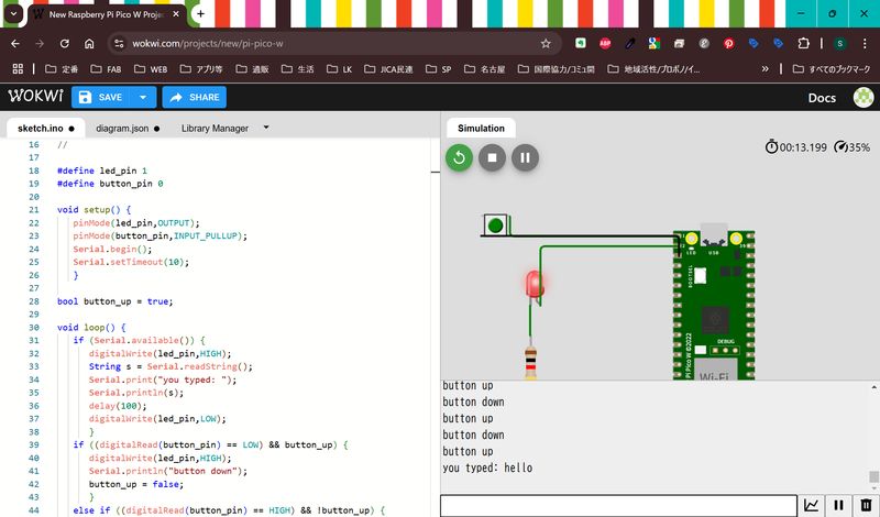
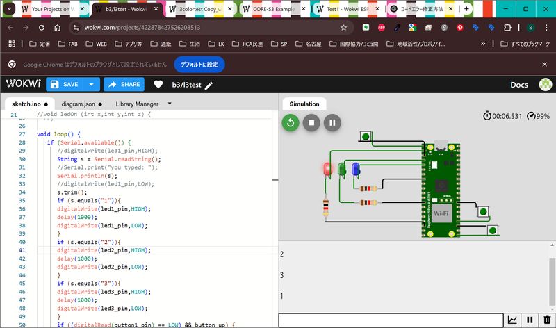
}I tried to check the source again, and noticed, it seems the place I close “if{}” is different.
I changed the place for “}”. Now it works!!
#define led1_pin 1
#define led2_pin 2
#define led3_pin 3
#define button1_pin 0
#define button2_pin 16
#define button3_pin 18

void setup() {
   pinMode(led1_pin,OUTPUT);
   pinMode(led2_pin,OUTPUT);
   pinMode(led3_pin,OUTPUT);
   pinMode(button1_pin,INPUT_PULLUP);
   pinMode(button2_pin,INPUT_PULLUP);
   pinMode(button3_pin,INPUT_PULLUP);
   Serial.begin(9600);
   Serial.setTimeout(10);
   }

bool button_up = true;

//void ledOn (int x,int y,int z) {
  //digitalWrite(led1_pin,x);
  //digitalWrite(led2_pin,y);
  //digitalWrite(led3_pin,z);
  //}

void loop() {
   if (Serial.available()) {
      String s = Serial.readString();
      Serial.print("you typed: ");
      Serial.println(s);
      s.trim();
      if (s.equals("1")){
      digitalWrite(led1_pin,HIGH);
      delay(1000);
      digitalWrite(led1_pin,LOW);
      }
      if (s.equals("2")){
      digitalWrite(led2_pin,HIGH);
      delay(1000);
      digitalWrite(led2_pin,LOW);
      }
      if (s.equals("3")){
      digitalWrite(led3_pin,HIGH);
      delay(1000);
      digitalWrite(led3_pin,LOW);
      }
    }
  if ((digitalRead(button1_pin) == LOW) && button_up) {
      digitalWrite(led1_pin,HIGH);
      digitalWrite(led2_pin,LOW);
      digitalWrite(led3_pin,LOW);
      Serial.println("Red down");
      button_up = false;
      delay(1000);
      }
  if ((digitalRead(button1_pin) == HIGH) && !button_up) {
      digitalWrite(led1_pin,LOW);
      digitalWrite(led2_pin,LOW);
      digitalWrite(led3_pin,LOW);
      Serial.println("Red up");
      button_up = true;
      delay(1000);
      }
  if ((digitalRead(button2_pin) == LOW) && button_up) {
      digitalWrite(led1_pin,LOW);
      digitalWrite(led2_pin,HIGH);
      digitalWrite(led3_pin,LOW);
      Serial.println("Green down");
      button_up = false;
      delay(1000);
      }
  if ((digitalRead(button2_pin) == HIGH) && !button_up) {
      digitalWrite(led1_pin,LOW);
      digitalWrite(led2_pin,LOW);
      digitalWrite(led3_pin,LOW);
      Serial.println("Green up");
      button_up = true;
      delay(1000);
      }
  if ((digitalRead(button3_pin) == LOW) && button_up) {
      digitalWrite(led1_pin,LOW);
      digitalWrite(led2_pin,LOW);
      digitalWrite(led3_pin,HIGH);
      Serial.println("Blue down");
      button_up = false;
      delay(1000);
      }
  else if ((digitalRead(button3_pin) == HIGH) && !button_up) {
      digitalWrite(led1_pin,LOW);
      digitalWrite(led2_pin,LOW);
      digitalWrite(led3_pin,LOW);
      Serial.println("Blue up");
      button_up = true;
      delay(1000);
      }
  }
Try to use functions 2
I tried to use function for button up/down.
// Program to blink 3 leds
// Created by Shoko Kudomi, fab academy 2025
// Referring to "hello.button-blink.RP2040.1.ino" by Neil Gershenfeld 12/28/23
#define led1_pin 1
#define led2_pin 2
#define led3_pin 3
#define button1_pin 0
#define button2_pin 16
#define button3_pin 18

void setup() {
   pinMode(led1_pin,OUTPUT); //LED1 connected as output device to pin 1
   pinMode(led2_pin,OUTPUT); //LED2 connected as output device to pin 2
   pinMode(led3_pin,OUTPUT); //LED3 connected as output device to pin 3
   pinMode(button1_pin,INPUT_PULLUP); //Button1 connected as input device to pin 0
   pinMode(button2_pin,INPUT_PULLUP); //Button2 connected as input device to pin 16
   pinMode(button3_pin,INPUT_PULLUP); //Button3 connected as input device to pin 18
   Serial.begin(9600); // Turn on serial monitor at 9600 baud rate(communication speed)
   Serial.setTimeout(10);
   }

bool button_up = true;

void LEDon (int x,int y,int z) {
  digitalWrite(led1_pin,x); // define LED1 as x
  digitalWrite(led2_pin,y); // define LED2 as y
  digitalWrite(led3_pin,z); // define LED3 as z
  }

void loop() {
   if (Serial.available()) {
      String s = Serial.readString(); //Read message you typed to Serial monitor
      Serial.print("you typed: "); //Send message to Serial monitor
      Serial.println(s); //Send the message to Serial monitor with line break
      s.trim();
      if (s.equals("1")){ //If the text you typed is 1
      digitalWrite(led1_pin,HIGH); // Turn on LED1
      delay(1000); //Wait 1 second
      digitalWrite(led1_pin,LOW); // Turn off LED1
      }
      if (s.equals("2")){ //If the text you typed is 2
      digitalWrite(led2_pin,HIGH); // Turn on LED2
      delay(1000); //Wait 1 second
      digitalWrite(led2_pin,LOW); // Turn off LED2
      }
      if (s.equals("3")){ //If the text you typed is 3
      digitalWrite(led3_pin,HIGH); // Turn on LED3
      delay(1000); //Wait 1 second
      digitalWrite(led3_pin,LOW); // Turn off LED3
      }
    }
  if ((digitalRead(button1_pin) == LOW) && button_up) {
      LEDon(1,0,0); // Turn on LED1
      Serial.println("Red down"); //Send the message to Serial monitor with line break
      button_up = false;
      delay(1000); //Wait 1 second
      }
  if ((digitalRead(button1_pin) == HIGH) && !button_up) {
      LEDon(0,0,0); // Turn off all LEDs
      Serial.println("Red up"); //Send the message to Serial monitor with line break
      button_up = true;
      delay(1000); //Wait 1 second
      }
  if ((digitalRead(button2_pin) == LOW) && button_up) {
      LEDon(0,1,0); // Turn on LED2
      Serial.println("Green down"); //Send the message to Serial monitor with line break
      button_up = false;
      delay(1000); //Wait 1 second
      }
  if ((digitalRead(button2_pin) == HIGH) && !button_up) {
      LEDon(0,0,0); // Turn off all LEDs
      Serial.println("Green up"); //Send the message to Serial monitor with line break
      button_up = true;
      delay(1000); //Wait 1 second
      }
  if ((digitalRead(button3_pin) == LOW) && button_up) {
      LEDon(0,0,1); // Turn on LED3
      Serial.println("Blue down"); //Send the message to Serial monitor with line break
      button_up = false;
      delay(1000); //Wait 1 second
      }
  else if ((digitalRead(button3_pin) == HIGH) && !button_up) {
      LEDon(0,0,0); // Turn off all LEDs
      Serial.println("Blue up"); //Send the message to Serial monitor with line break
      button_up = true;
      delay(1000); //Wait 1 second
      }
  }
RP2040 and ESP32 on the simulator
I tried same code on both Pi Pico W and xiao
ESP32-C3.
Basically, it works with the same code. Regarding the code, all
I have to do is change the pin number.
(Xiao has less port than
ESP-32 itself.)
Try Micropython
I also tried Micropython. Used
test code below from class page and tried the same thing I did with Aruduino language. hello.button-blink.RP2040.1.py
For Python, I got error about
indent. You have to be careful about indent after line of ”if~:”.
Basically I arranged the cord by myself, but I also used ChatGPT to analyze the error of my cord. This is suggested by Rico-san.
I created the code in the following steps.
- I referred to Neil's hello.button-blink.RP2040.1.py code, added LEDs and buttons to the simulator, and added the same to the code. But it didn't work.
- I attached the code and asked ChatGPT to "analyze the error in this code."
- ChatGPT replied that "In Python, you need to indent correctly after an if statement."
- I rewrote the code according to the suggestions, and it worked.
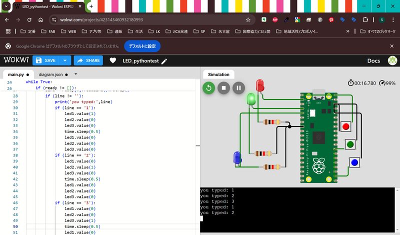
The code is as below.
# Program to blink 3 leds
# Created by Shoko Kudomi, fab academy 2025
# Referring to "hello.button-blink.RP2040.1.py" by Neil Gershenfeld 12/28/23

from machine import Pin
import sys,select,time

led_pin1 = 1
led_pin2 = 2
led_pin3 = 3
button1_pin = 0
button2_pin = 16
button3_pin = 17

led1 = Pin(led_pin1,Pin.OUT) # LED1 connected as output device to pin 1
led2 = Pin(led_pin2,Pin.OUT) # LED2 connected as output device to pin 2
led3 = Pin(led_pin3,Pin.OUT) # LED3 connected as output device to pin 3
button1 = Pin(button1_pin,Pin.IN,Pin.PULL_UP) #Button1 connected as input device to pin 0
button2 = Pin(button2_pin,Pin.IN,Pin.PULL_UP) #Button2 connected as input device to pin 16
button3 = Pin(button3_pin,Pin.IN,Pin.PULL_UP) #Button3 connected as input device to pin 17

button_up = True

while True:
    ready = select.select([sys.stdin],[],[],0)[0]
    if (ready != []):
        line = ready[0].readline().rstrip()
        if (line != ''):
            print('you typed:',line) #Send message to Serial monitor with your typed text
            if (line == '1'): #If the text you typed is 1
                led1.value(1) #Turn on LED1
                led2.value(0) #Turn off LED2
                led3.value(0) #Turn off LED3
                time.sleep(0.1) #Wait 0.1 second
                led1.value(0) #Turn off LED1
                led2.value(0) #Turn off LED2
                led3.value(0) #Turn off LED3
            if (line == '2'): #If the text you typed is 2
                led1.value(0) #Turn off LED1
                led2.value(1) #Turn on LED2
                led3.value(0) #Turn off LED3
                time.sleep(0.1) #Wait 0.1 second
                led1.value(0) #Turn off LED1
                led2.value(0) #Turn off LED2
                led3.value(0) #Turn off LED3
            if (line == '3'): #If the text you typed is 3
                led1.value(0) #Turn off LED1
                led2.value(0) #Turn off LED2
                led3.value(1) #Turn on LED3
                time.sleep(0.1) #Wait 0.1 second
                led1.value(0) #Turn off LED1
                led2.value(0) #Turn off LED2
                led3.value(0) #Turn off LED3
    if ((button1.value() == 0) and button_up): #When button 1 is pressed
        led1.value(1) #Turn on LED1
        led2.value(0) #Turn off LED2
        led3.value(0) #Turn off LED3
        print('button1 down') #Send message to Serial monitor
        button_up = False
    if ((button1.value() == 1) and (not button_up)): #When button 1 is not pressed
        led1.value(0) #Turn off LED1
        led2.value(0) #Turn off LED2
        led3.value(0) #Turn off LED3
        print('button1 up') #Send message to Serial monitor
        button_up = True
    if ((button2.value() == 0) and button_up): #When button 2 is pressed
        led1.value(0) #Turn off LED1
        led2.value(1) #Turn on LED2
        led3.value(0) #Turn off LED3
        print('button2 down') #Send message to Serial monitor
        button_up = False
    if ((button2.value() == 1) and (not button_up)): #When button 2 is not pressed
        led1.value(0) #Turn off LED1
        led2.value(0) #Turn off LED2
        led3.value(0) #Turn off LED3
        print('button2 up') #Send message to Serial monitor
        button_up = True
    if ((button3.value() == 0) and button_up): #When button 3 is pressed
        led1.value(0) #Turn off LED1
        led2.value(0) #Turn off LED2
        led3.value(1) #Turn on LED3
        print('button3 down') #Send message to Serial monitor
        button_up = False
    elif ((button3.value() == 1) and (not button_up)): #When button 3 is not pressed
        led1.value(0) #Turn off LED1
        led2.value(0) #Turn off LED2
        led3.value(0) #Turn off LED3
        print('button3 up') #Send message to Serial monitor
        button_up = True
Not complete: Try other modules
I also tried RGB LED, and buzzer. I'm still struggling with using potentiometer (not solved yet).
I made the mistake of getting the pin numbers wrong, probably because I got confused when there were too many pins. I basically referred to the Wokwi module explanation.
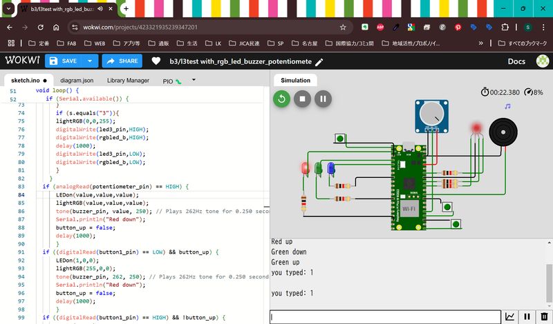
The code is as shown:
// Program to blink 3 leds
// Created by Shoko Kudomi, fab academy 2025
// Referring to "hello.button-blink.RP2040.1.ino" by Neil Gershenfeld 12/28/23
#define led1_pin 1
#define led2_pin 2
#define led3_pin 3
#define rgbled_r 26
#define rgbled_g 27
#define rgbled_b 28
#define buzzer_pin 22
#define potentiometer_pin 19
#define button1_pin 0
#define button2_pin 16
#define button3_pin 18


void setup() {
   pinMode(led1_pin,OUTPUT);
   pinMode(led2_pin,OUTPUT);
   pinMode(led3_pin,OUTPUT);
   pinMode(rgbled_r,OUTPUT);
   pinMode(rgbled_g,OUTPUT);
   pinMode(rgbled_b,OUTPUT);
   pinMode(buzzer_pin,OUTPUT);
   pinMode(button1_pin,INPUT_PULLUP);
   pinMode(button2_pin,INPUT_PULLUP);
   pinMode(button3_pin,INPUT_PULLUP);
   pinMode(potentiometer_pin, INPUT);
   Serial.begin(9600);
   Serial.setTimeout(10);
   }

bool button_up = true;

int count = 0;

void LEDon (int x,int y,int z) {
  digitalWrite(led1_pin,x);
  digitalWrite(led2_pin,y);
  digitalWrite(led3_pin,z);
  }

void lightRGB(int red, int green, int blue) {
  analogWrite(rgbled_r, red);
  analogWrite(rgbled_g, green);
  analogWrite(rgbled_b, blue);
}

int value = analogRead(potentiometer_pin);

void loop() {
   if (Serial.available()) {
      String s = Serial.readString();
      Serial.print("you typed: ");
      Serial.println(s);
      s.trim();
      if (s.equals("1")){
      lightRGB(255,0,0);
      tone(buzzer_pin, 262, 250); // Plays 262Hz tone for 0.250 seconds
      digitalWrite(led1_pin,HIGH);
      digitalWrite(rgbled_r,HIGH);
      delay(1000);
      digitalWrite(led1_pin,LOW);
      digitalWrite(rgbled_r,LOW);
      }
      if (s.equals("2")){
      lightRGB(0,255,0);
      digitalWrite(led2_pin,HIGH);
      digitalWrite(rgbled_g,HIGH);
      delay(1000);
      digitalWrite(led2_pin,LOW);
      digitalWrite(rgbled_g,LOW);
      }
      if (s.equals("3")){
      lightRGB(0,0,255);
      digitalWrite(led3_pin,HIGH);
      digitalWrite(rgbled_b,HIGH);
      delay(1000);
      digitalWrite(led3_pin,LOW);
      digitalWrite(rgbled_b,LOW);
      }
    }
  if (analogRead(potentiometer_pin) == HIGH) {
      LEDon(value,value,value);
      lightRGB(value,value,value);
      tone(buzzer_pin, value, 250); // Plays 262Hz tone for 0.250 seconds
      Serial.println("Red down");
      button_up = false;
      delay(1000);
      }
  if ((digitalRead(button1_pin) == LOW) && button_up) {
      LEDon(1,0,0);
      lightRGB(255,0,0);
      tone(buzzer_pin, 262, 250); // Plays 262Hz tone for 0.250 seconds
      Serial.println("Red down");
      button_up = false;
      delay(1000);
      }
  if ((digitalRead(button1_pin) == HIGH) && !button_up) {
      LEDon(0,0,0);
      lightRGB(0,0,0);
      Serial.println("Red up");
      button_up = true;
      delay(1000);
      }
  if ((digitalRead(button2_pin) == LOW) && button_up) {
      LEDon(0,1,0);
      lightRGB(0,255,0);
      analogWrite(rgbled_g, 128 + sin(2 * PI / 60 * count * 0.6) * 127);
      Serial.println("Green down");
      button_up = false;
      delay(1000);
      }
  if ((digitalRead(button2_pin) == HIGH) && !button_up) {
      LEDon(0,0,0);
      lightRGB(0,0,0);
      Serial.println("Green up");
      button_up = true;
      delay(1000);
      }
  if ((digitalRead(button3_pin) == LOW) && button_up) {
      LEDon(0,0,1);
      lightRGB(0,0,255);
      analogWrite(rgbled_b, 128 + sin(2 * PI / 60 * count * 0.7) * 127);
      Serial.println("Blue down");
      button_up = false;
      delay(1000);
      }
  else if ((digitalRead(button3_pin) == HIGH) && !button_up) {
      LEDon(0,0,0);
      lightRGB(0,0,0);
      Serial.println("Blue up");
      button_up = true;
      delay(1000);
      }
  }
Outcomes
I could try some processors, boards, languages. Arduino toolchain seems very easy and understandable, so I may choose it. However if I have time, I would like to try python more also.
I also would like to try more modules.
*This page uses Google Translate to translate some sentences.