#9 Input Devices
This week I learned how to measure something with a sensors.
Assignment
Group assignment
- Probe an input device(s)'s analog levels and digital signals
Individual assignment
- Measure something: add a sensor to a microcontroller board that you have designed and read it
Outcomes
What did I do this week: 1. Group Assignment
The group assignment page - week09
Probe an input device(s)'s analog levels and digital signals
We used an oscilloscope to read the signal waveforms obtained from each input device board that each member had made.
For details, please see the group page: The group assignment page - week09
What did I do this week: 2. Individual assignment
Measure something: add a sensor to a microcontroller board that you have designed and read it
Procedure
I plan to use touch sensors in the final project. In class, we learned several ways to implement touch sensors.
Step Response1pin: A method that uses electrodes from the outside world.
Some processors, such as the ESP32, have built-in touch measurement functionality, and you
can use this, or some, such as the SAMD21, can be used as is by loading a library.
Also, with any processor, you can set custom peripherals to the PIO in the assembly to enable
touch.
2pin: A method that creates electrodes by sending pulses from the transmitter to the receiver, and when touched, the pulse changes, which can be read.
For this week's assignment I decided to try out different touch sensors.
- Processor (xiao ESP32S3)
- 1 pin with Resistor (xiao RP2040)
- 2 pin (xiao RP2040)
- MPR121 (xiao ESP32C3)
Processor - ESP32
Last week I created a board using xiao, so I decided to first try out a method that could be
implemented using the functions of the processor itself.
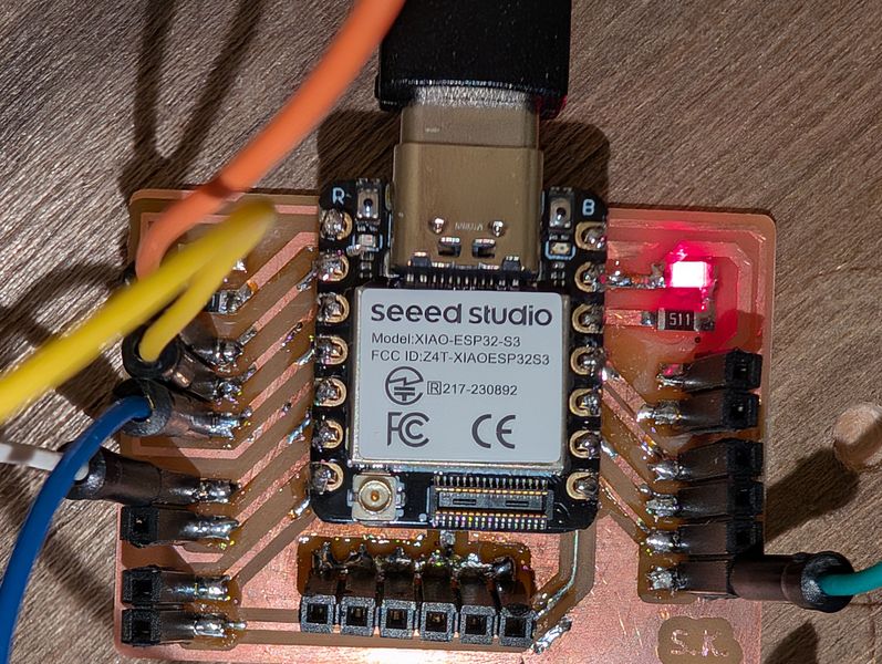
I decided to plug the xiaoESP32 into the board I created last week to test its reaction.
*See Week 8 for the design of the board I created last week.
I tried it with the ESP32C3, but got an error. It seems that it can only be implemented with the S3.
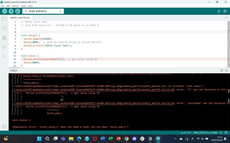
So I borrowed an ESP32S3 from the instructor Nagano-san. The pinout for the S3 is as follows:
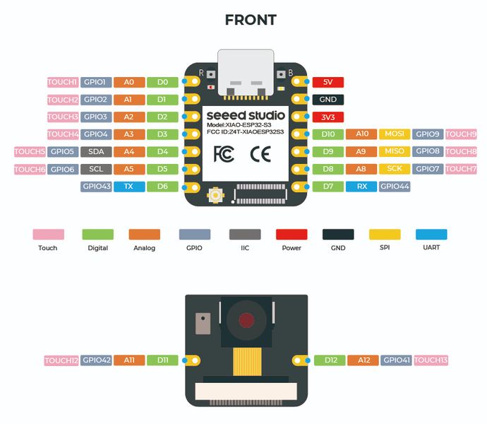
TOUCH - - — Arduino ESP32 latest documentation
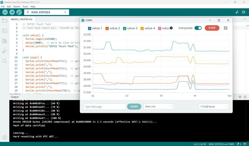
I tried the following code from the above page:
// ESP32 Touch Test
// Just test touch pin - Touch0 is T0 which is on GPIO 4.

void setup() {
  Serial.begin(115200);
  delay(1000);  // give me time to bring up serial monitor
  Serial.println("ESP32 Touch Test");
}

void loop() {
  Serial.println(touchRead(T1));  // get value using T1
  delay(1000);
}
It worked without any problems.
Next, I tried increasing the number of pins.
I tried the maximum number of touch pins for S3.
At first, I tried it with the following code.
// ESP32 Touch Test
// Just test touch pin - Touch0 is T0 which is on GPIO 4.
void setup() {
Serial.begin(115200);
delay(1000); // give me time to bring up serial monitor
Serial.println("ESP32 Touch Test");
}
void loop() {
Serial.println(touchRead(T1)); // get value using T1
delay(1000);
Serial.println(touchRead(T2)); // get value using T2
delay(1000);
Serial.println(touchRead(T3)); // get value using T3
delay(1000);
Serial.println(touchRead(T4)); // get value using T4
delay(1000);
Serial.println(touchRead(T5)); // get value using T5
delay(1000);
Serial.println(touchRead(T6)); // get value using T6
delay(1000);
Serial.println(touchRead(T7)); // get value using T7
delay(1000);
Serial.println(touchRead(T8)); // get value using T8
delay(1000);
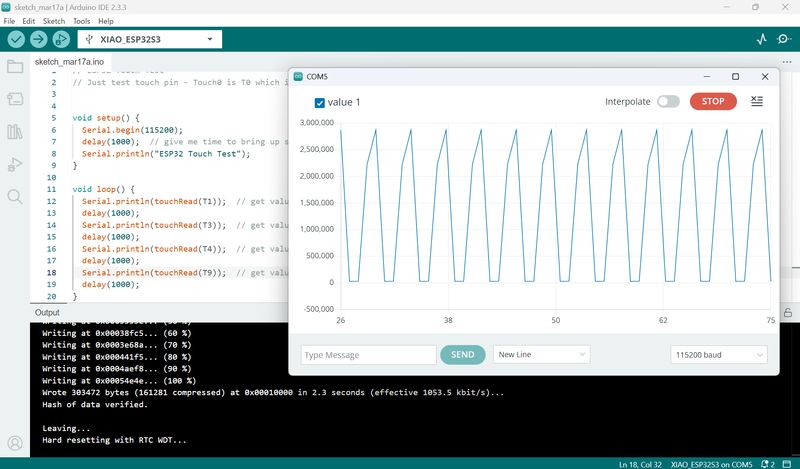
Serial.println(touchRead(T9)); // get value using T9
delay(1000);
}
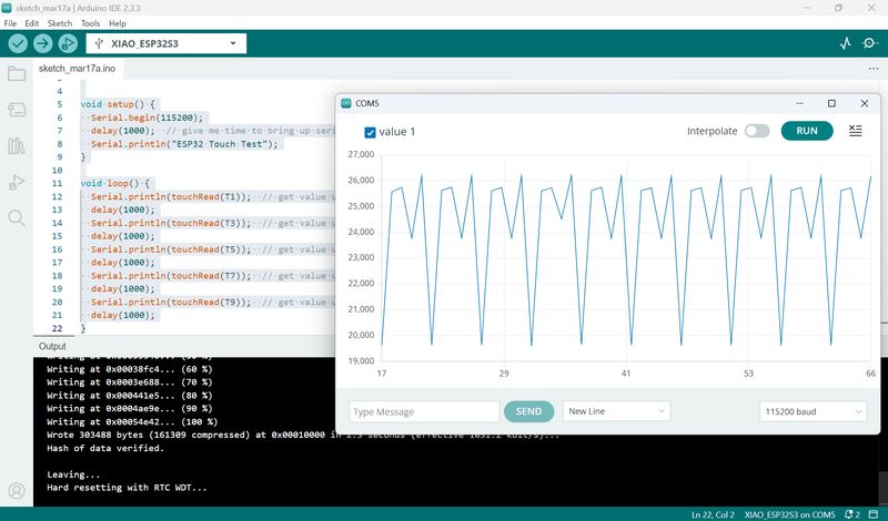
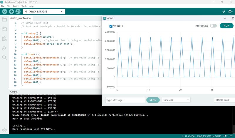
Even without touching it, the following behavior occurred. I thought something was wrong, so I decided to reduce the number of pins a little.
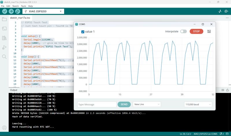
I made it 5 pins.
// ESP32 Touch Test
// Just test touch pin - Touch0 is T0 which is on GPIO 4.

void setup() {
  Serial.begin(115200);
  delay(1000);  // give me time to bring up serial monitor
  Serial.println("ESP32 Touch Test");
}

void loop() {
  Serial.println(touchRead(T1));  // get value using T1
  delay(1000);
  Serial.println(touchRead(T3));  // get value using T3
  delay(1000);
  Serial.println(touchRead(T5));  // get value using T5
  delay(1000);
  Serial.println(touchRead(T7));  // get value using T7
  delay(1000);
  Serial.println(touchRead(T9));  // get value using T9
  delay(1000);
}
It still responds without anything.
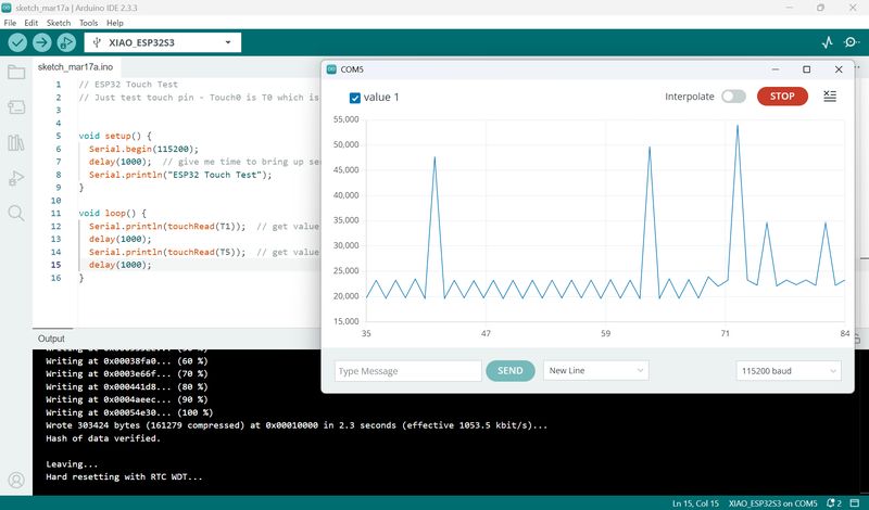
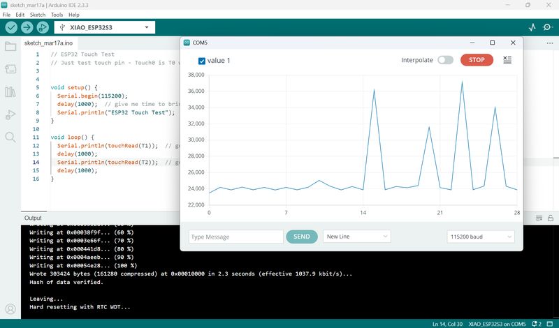
Even when the pin number was reduced to two, the following reactions were observed:
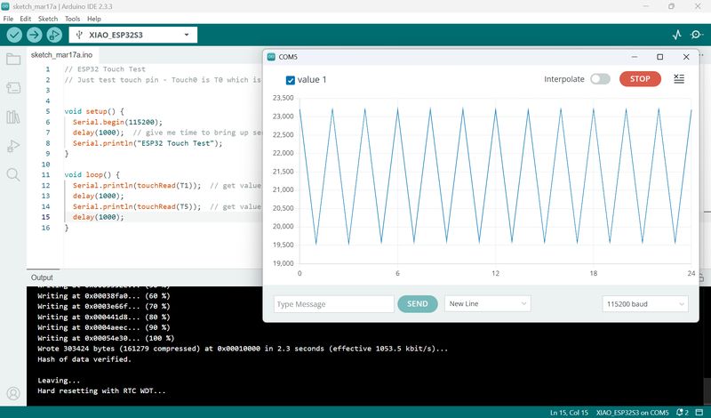
When I touched it, the numbers changed dramatically.
Then, I tried using a longer cord with four pins.
There was no reaction when I touched it.
Debug
So I decided to add T1, T2 in that order and test.// ESP32 Touch Test
// Just test touch pin - Touch0 is T0 which is on GPIO 4.
void setup() {
Serial.begin(115200);
delay(1000); // give me time to bring up serial monitor
Serial.println("ESP32 Touch Test");
}
void loop() {
Serial.println(touchRead(T1)); // get value using T1
delay(1000);
Serial.println(touchRead(T2)); // get value using T1
delay(1000);
}
It responded well, so I made it three.
// ESP32 Touch Test
// Just test touch pin - Touch0 is T0 which is on GPIO 4.

void setup() {
  Serial.begin(115200);
  delay(1000);  // give me time to bring up serial monitor
  Serial.println("ESP32 Touch Test");
}

void loop() {
  Serial.println(touchRead(T1));  // get value using T1
  delay(1000);
  Serial.println(touchRead(T2));  // get value using T2
  delay(1000);
  Serial.println(touchRead(T3));  // get value using T3
  delay(1000);
}
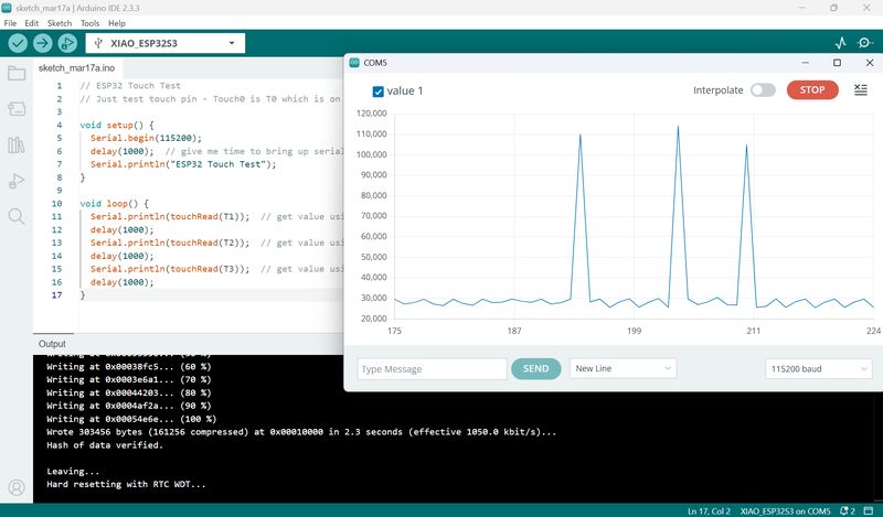
But when I added the T4, it stopped working…
When I tried adding T5, T1 to T3 responded, but only T5 did not respond…
I checked with the instructors and got the following advice from Nagano-san.
- In the above code, multiple Ts are serial printed one after another, so the graph is
not accurate. Serial.print needs to be used as shown on the following page.
ArduinoIDEのシリアルプロッタで2個以上のデータを表示させる #電子工作 - Qiita
// ESP32 Touch Test
// Just test touch pin - Touch0 is T0 which is on GPIO 4.

void setup() {
  Serial.begin(115200);
  delay(1000);  // give me time to bring up serial monitor
  Serial.println("ESP32 Touch Test");
}

void loop() {
  Serial.print(touchRead(T1));  // get value using T1
  Serial.print(",");
  Serial.print(touchRead(T2));  // get value using T2
  Serial.print(",");
  Serial.print(touchRead(T3));  // get value using T3
  Serial.print(",");
  Serial.print(touchRead(T4));  // get value using T
  Serial.print(",");
  Serial.println(touchRead(T5));  // get value using T5
  delay(1000);
}
But it didn't work.
Tsuchiya-san also gave me the following additional advice:
- The basic rule is not to pass current through the touch sensor pins or connect them to other circuits, and it is not OK to connect LEDs or resistors directly to the touch pins.
- Instead of using T4 and T5, it might be a good idea to use T7 to T9 on the opposite side. T5 and T6 are used for I2C, so it is probably best not to use them.
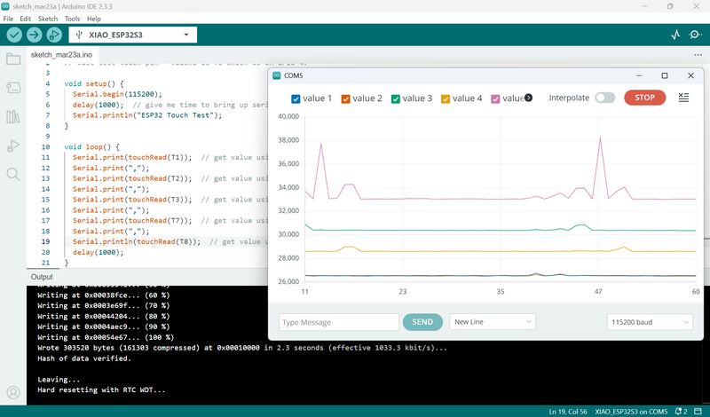
I modified the code as follows:
// ESP32 Touch Test
// Just test touch pin - Touch0 is T0 which is on GPIO 4.

void setup() {
  Serial.begin(115200);
  delay(1000);  // give me time to bring up serial monitor
  Serial.println("ESP32 Touch Test");
}

void loop() {
  Serial.print(touchRead(T1));  // get value using T1
  Serial.print(",");
  Serial.print(touchRead(T2));  // get value using T2
  Serial.print(",");
  Serial.print(touchRead(T3));  // get value using T3
  Serial.print(",");
  Serial.print(touchRead(T7));  // get value using T7
  Serial.print(",");
  Serial.println(touchRead(T8));  // get value using T8
  delay(1000);
}
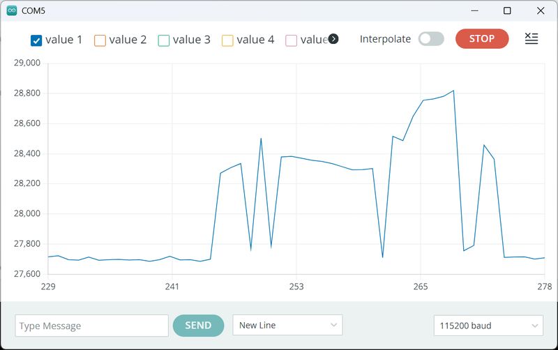
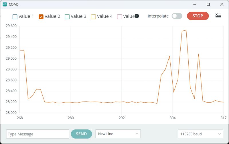
It now responds nicely!
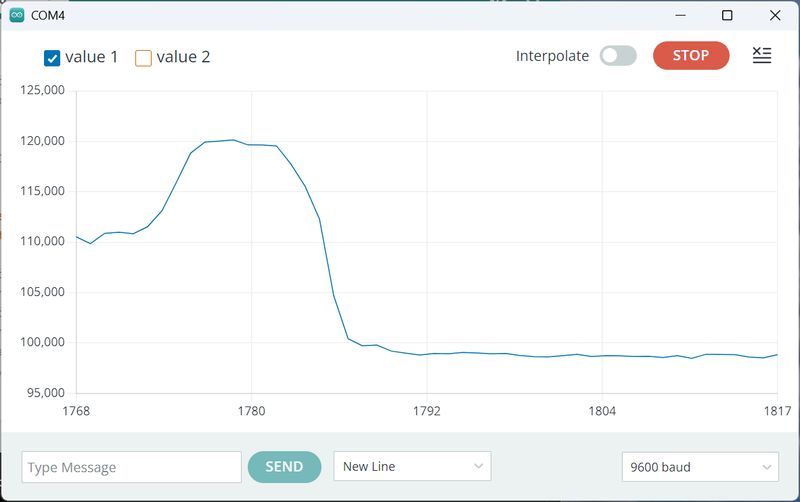
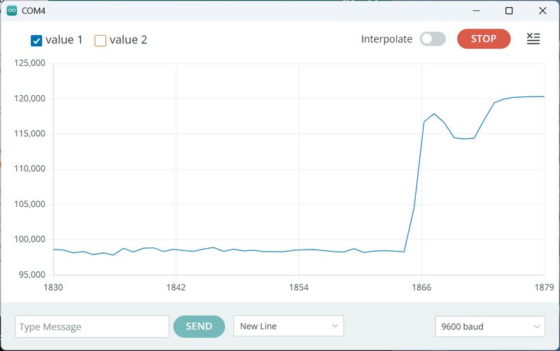
If you touch the connected pins directly, it responds as shown below.
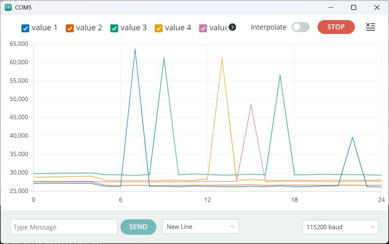
I found that the value was larger when I touched both wires at the same time as GND.
Also, the value roughly doubled when I touched both wires at the same time.
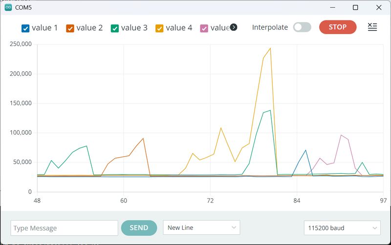
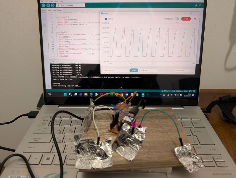
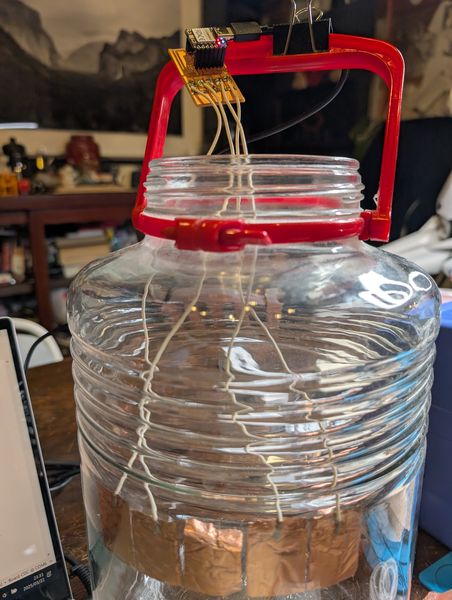
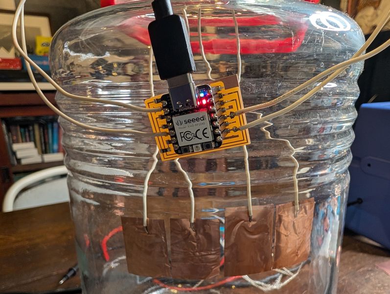
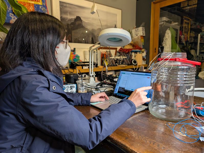
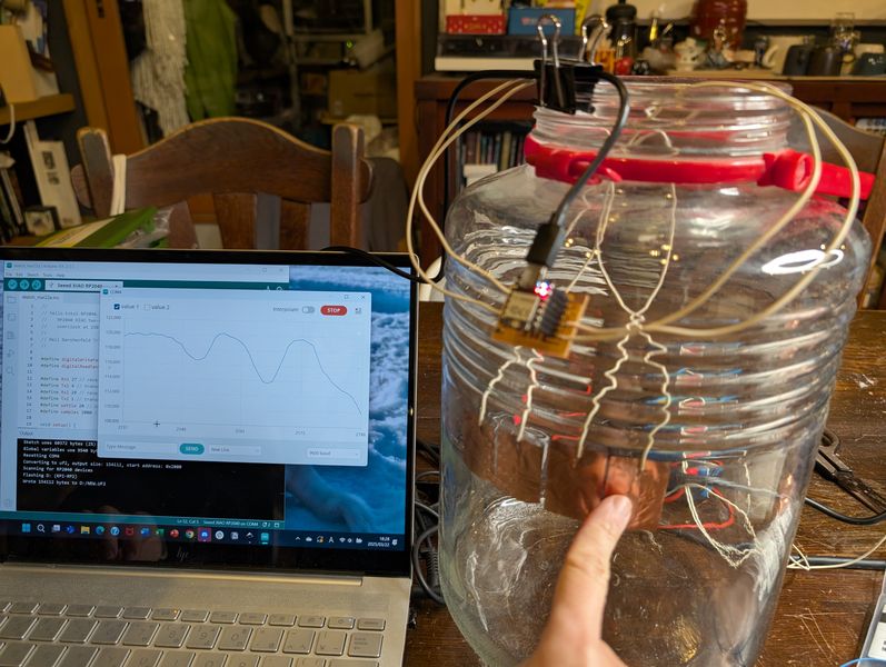
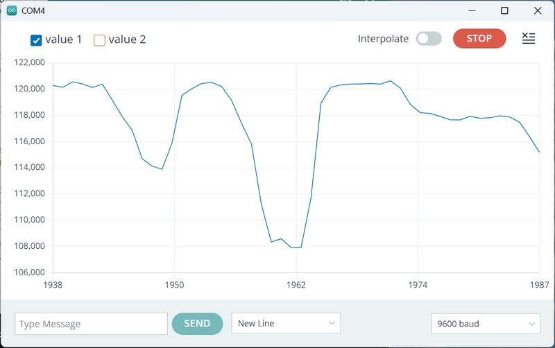
Assuming the actual Final Project, I tested it by sticking it to a glass bottle.
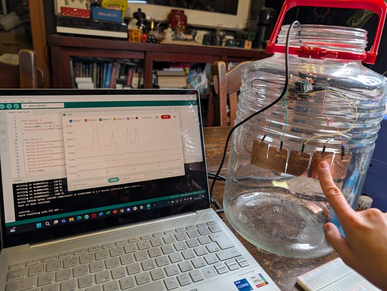
However, the values seem to vary.
Looking at the values carefully, I realized that the problem was probably that the
reaction was too small, so there was no significant difference between when it was not
touched and when it was touched, like when it was touched directly.
I need to research a way to get a large reaction when touched, even if it is far away from
the board or through glass.
If one pin is touched
When covered with hand
Responses for each pin
Results
The results are as follows:
| T1 | 28600 |
|---|---|
| T2 | 27500 |
| T3 | 32000 |
| T7 | 30700 |
| T8 | 29100 |
Resources:
https://docs.espressif.com/projects/arduino-esp32/en/latest/api/touch.html
https://wiki.seeedstudio.com/xiao_esp32s3_getting_started/
https://wiki.seeedstudio.com/XIAO_ESP32C3_Getting_Started/
https://wiki.seeedstudio.com/Seeeduino-XIAO/
https://github.com/espressif/esp-iot-solution/blob/release/v1.0/documents/touch_pad_solution/touch_sensor_design_en.md
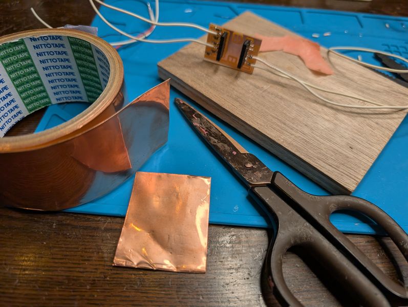
1 pin with Resistor (xiao RP2040)
Next, I tried using a resistor even if the processor had no function for a single pin.
I used Neil's board design and circuit as is, but decided to test how different resistors
would react differently depending on the resistance size by using different types of
resistors.
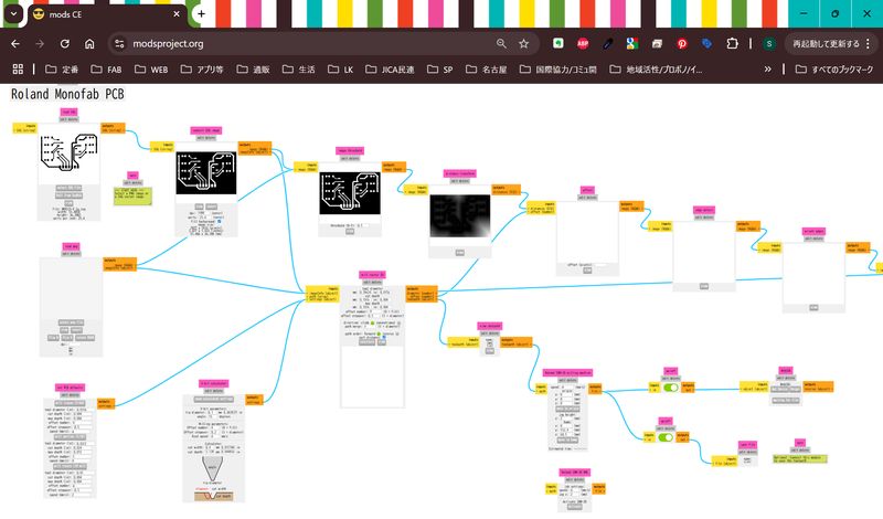
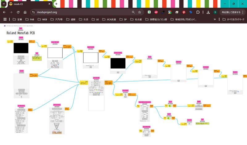
Milling
First, I cut the circuit. I changed the mill setting: offset 4 → 6
I added three types of resistors to the circuit: 100KΩ, 1MΩ, and 2MΩ.
I realized we didn't have any 2MΩ resistors in Kamakura inventory, but I had already cut
the board, so I connect two 1MΩ resistors in a tricky way…
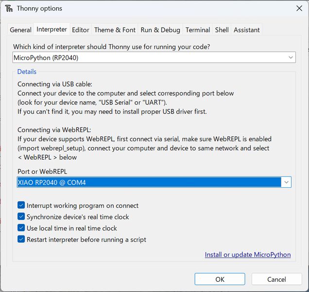
Python
As the only sample code available was in Python, I started by setting up to use
Python.
As this was my first time using Thonny, I struggled with setting it up and getting the
RP2040 to work.
I referred to the following page.
https://wiki.seeedstudio.com/XIAO-RP2040-with-MicroPython/
https://lab.seeed.co.jp/entry/2021/12/27/120000
https://www.zep.co.jp/utaguchi/article/z-picoled_all-da1/
https://msr-r.net/raspi-picow-setting/
Also, since I got an error related to a soft reboot and didn't know how to do it, I used
ChatGPT.
This is the setup on Thonny.
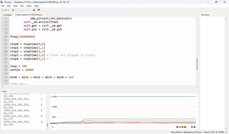
I used the following code.
#
# hello.steptime1.RP2040.py
#
# 1 pin step-response loading measurement with PIO
#
# Neil Gershenfeld 7/24/24
#
# This work may be reproduced, modified, distributed,
# performed, and displayed for any purpose, but must
# acknowledge this project. Copyright is retained and
# must be preserved. The work is provided as is; no
# warranty is provided, and users accept all liability.
#
# install MicroPython
#    https://micropython.org/download/RPI_PICO/
#

from machine import Pin,freq
import rp2

@rp2.asm_pio(set_init=rp2.PIO.OUT_HIGH)
def steptimer():
    #
    # initialize
    #
    pull()
    mov(y,osr) # move loop to y
    pull() # move settle to osr
    mov(x,null) # move count to x
    set(pins,1) # turn on pin
    #
    # main loop
    #
    label('main loop')
    #
    # charge up
    #
    set(pindirs,1) # set pin to output
    #
    # settle up
    #
    label('up settle')
    mov(isr,x)
    mov(x,osr)
    label('up settle loop')
    jmp(x_dec,'up settle loop')
    mov(x,isr)
    #
    # discharge
    #
    set(pindirs,0) # set pin to input
    #
    # time down
    #
    label('down loop')
    jmp(pin,'down jump')
    jmp('down continue')
    label('down jump')
    jmp(x_dec,'down loop')
    #
    # loop
    #
    label('down continue')
    jmp(y_dec,'main loop')
    #
    # push count
    #
    mov(isr,x)
    push()

class steptime:
    def __init__(self,sm_id,pin):
        self._sm = rp2.StateMachine(sm_id,steptimer,
            jmp_pin=pin,set_base=pin)
        self._sm.active(True)
        self.get = self._sm.get
        self.put = self._sm.put

freq(250000000)

step0 = steptime(0,0)
step1 = steptime(1,1)
step2 = steptime(2,2)
step3 = steptime(3,4) # these are flipped in pinout
step4 = steptime(4,3) # "

loop = 200
settle = 20000

min0 = min1 = min2 = min3 = min4 = 1e6

while True:
    step0.put(loop)
    step0.put(settle)
    result0 = 4294967296-step0.get() # +1 for init 0
    if (result0 < min0): min0 = result0
    step1.put(loop)
    step1.put(settle)
    result1 = 4294967296-step1.get()
    if (result1 < min1): min1 = result1
    step2.put(loop)
    step2.put(settle)
    result2 = 4294967296-step2.get()
    if (result2 < min2): min2 = result2
    step3.put(loop)
    step3.put(settle)
    result3 = 4294967296-step3.get()
    if (result3 < min3): min3 = result3
    step4.put(loop)
    step4.put(settle)
    result4 = 4294967296-step4.get()
    if (result4 < min4): min4 = result4
    print(f"7500,{result0-min0},{result1-min1},{result2-min2},\
       {result3-min3},{result4-min4}") # 7500 for scale
It worked fine!!
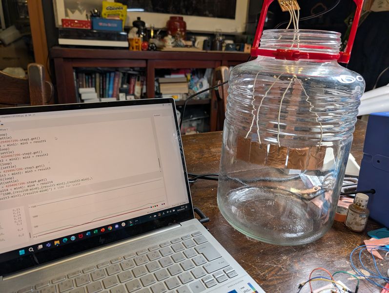
However, the response is too small. I looked at the code and noticed that the bottom part was the Scale specification, so I edited it.
print(f"7500,{result0-min0},{result1-min1},{result2-min2},\
{result3-min3},{result4-min4}") # 7500 for scale
I edited the above as follows:
print(f"2500,{result0-min0},{result1-min1},{result2-min2},\\
   {result3-min3},{result4-min4}") # 2500 for scale
I also decided to try it with thinner wire.
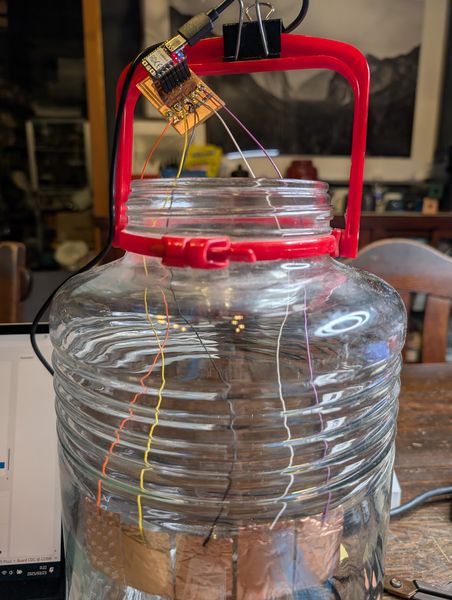
Since the reaction became even smaller, I changed the scale as follows:
print(f"500,{result0-min0},{result1-min1},{result2-min2},\\
   {result3-min3},{result4-min4}") # 500 for scale
Results
The results are as follows:
Horizontal: Length of wire × Vertical: Size of resistor
*I couldn't figure out the N/A part very well.
| No wire(board direct) | 25cm(thick) | 25cm(0.2㎜²) | ||
|---|---|---|---|---|
| 1 | 100k | 7500-15000 | 500 | 200 |
| 2 | 100k | ~15000 | 1000 | 200 |
| 3 | 1M | N/A | N/A | N/A |
| 4 | 1M | ~10000 | 6-700 | 400 |
| 5 | 2M | 8000~20000 | N/A | 500 |
2 pin (xiao RP2040)
I tried a method that uses 2 pins also.
Again, I used Neil's design and code.
I created and tested two types, 1MΩ and 100KΩ.
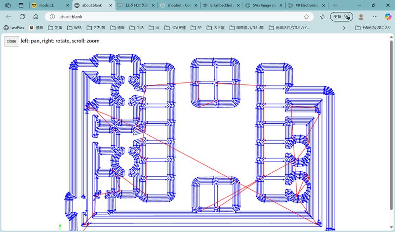
Toolpaths
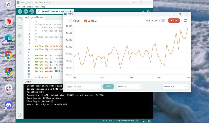
Code
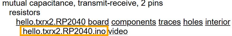
//
// hello.txtx2.RP2040.ino
//    RP2040 XIAO two-channel transmit-receive step-response hello-world
//    overclock at 250 MHz
//
// Neil Gershenfeld 7/10/23
//

#define digitalWriteFast(pin,val) (val ? sio_hw->gpio_set = (1 << pin) : sio_hw->gpio_clr = (1 << pin))
#define digitalReadFast(pin) ((1 << pin) & sio_hw->gpio_in)

#define Rx1 27 // receive 1 pin (D1)
#define Tx1 4 // transmit 1 pin (D9)
#define Rx2 29 // receive 2 pin (D3)
#define Tx2 1 // transmit 2 pin (D7)
#define settle 20 // settle time
#define samples 2000 // number of samples to accumulate

void setup() {
   Serial.begin(115200);
   }

void loop() {
   }

void setup1() {
   pinMode(Tx1,OUTPUT);
   pinMode(Tx2,OUTPUT);
   }

void loop1() {
   int32_t up1,down1,up2,down2;
   up1 = down1 = up2 = down2 = 0;
   for (int i = 0; i < samples; ++i) {
      digitalWriteFast(Tx1,HIGH); // charge up
      up1 += analogRead(Rx1); // read
      delayMicroseconds(settle); //settle
      digitalWriteFast(Tx1,LOW); // charge down
      down1 += analogRead(Rx1); // read
      delayMicroseconds(settle); // settle
      digitalWriteFast(Tx2,HIGH); // charge up
      up2 += analogRead(Rx2); // read
      delayMicroseconds(settle); //settle
      digitalWriteFast(Tx2,LOW); // charge down
      down2 += analogRead(Rx2); // read
      delayMicroseconds(settle); // settle
      }
   Serial.print(up1-down1); // send difference
   Serial.print(',');
   Serial.println(up2-down2); // send difference
   Serial.flush(); // finish communicating before measuring
   }
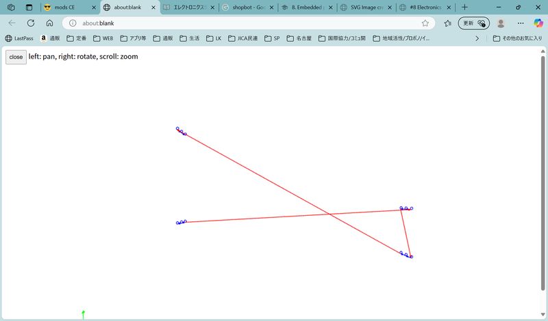
Assembly
I read it as follows:
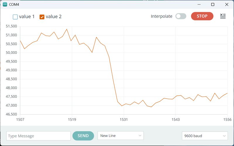
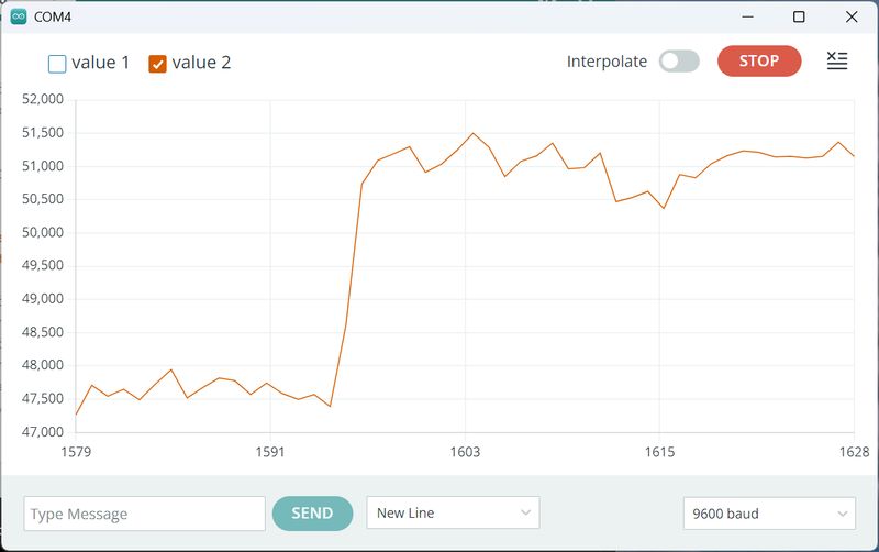
Value 1 = 1MΩ
Value 2 = 100KΩ
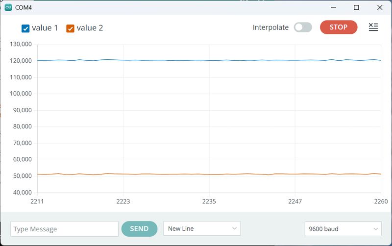
When I tap, I can see that it is responding.
This method was very instructive in learning how touch works.
However, this method requires two points to select one location.
Since I want to touch one country, I would like to implement it with one pin if possible,
so this method may not be suitable for my Final Project.
MPR121 (xiao ESP32C3)
As we saw in Week 6, ChatGPT recommends using the MPR121 to implement many touches, and I
was considering using it. So I conducted an experiment. This time, instructor,
Tsuchiya-san, had an MPR121 breakout board, so I borrowed it.
To use this board, it needs to be connected to a microcontroller. So I decided to design a
board that could be connected to the Xiao that I have.
Build a board for MPR121
The pinout for xiaoESP32-C3 is as follows:
https://wiki.seeedstudio.com/XIAO_ESP32C3_Getting_Started/
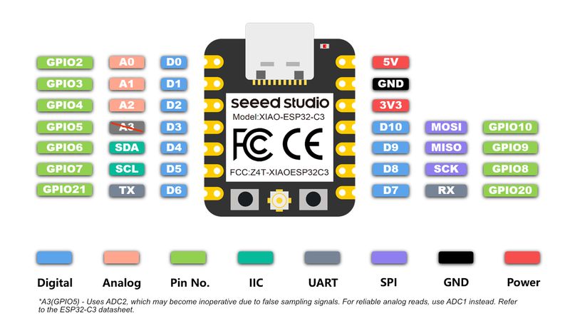
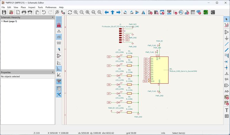
The schematic design is as follows.
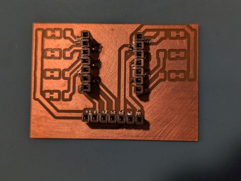
I've also included a circuit for an LED so that I can try out the output later.
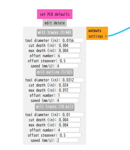
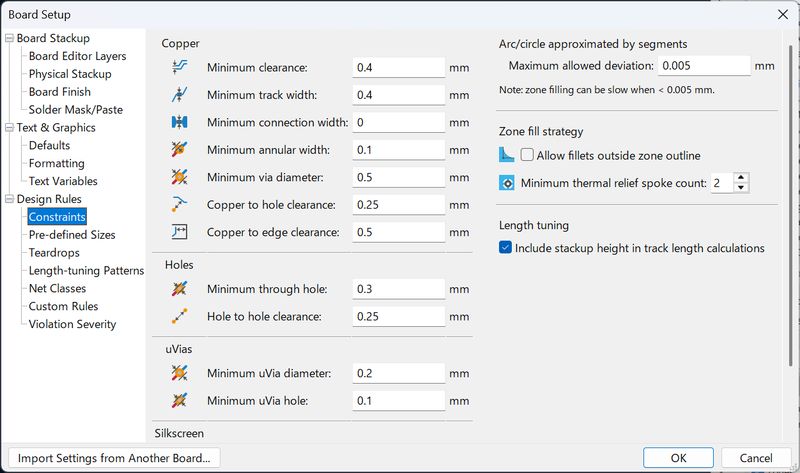
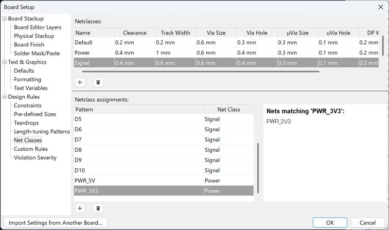
The design rules are set as follows:
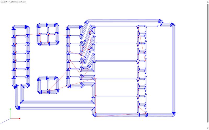
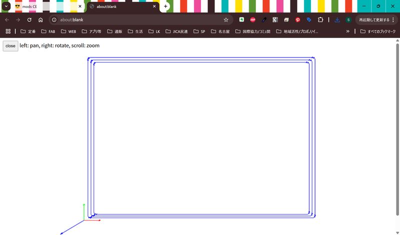
The PCB Design is as follows.
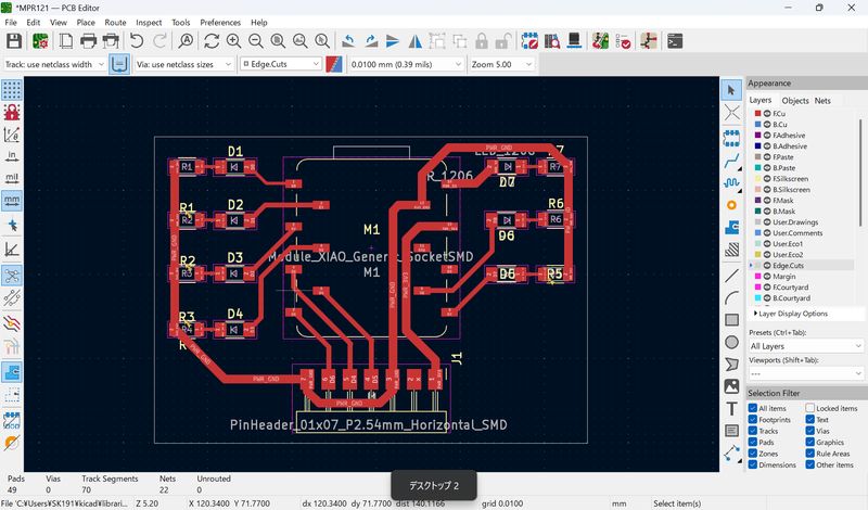
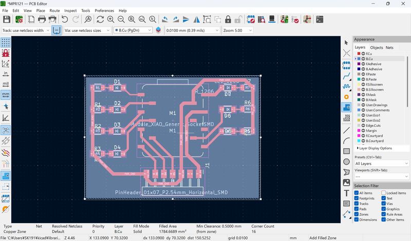
The key words to remember when checking milling designs are:
White: Keep
Black: Cut
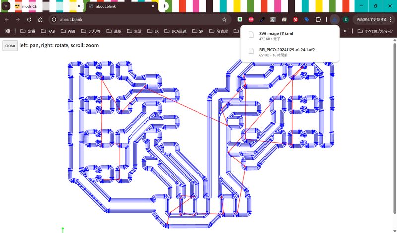
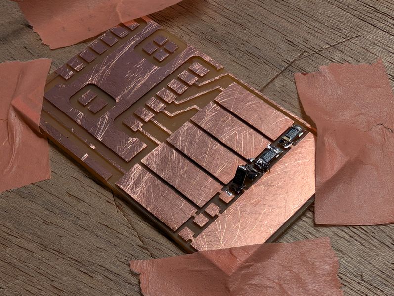
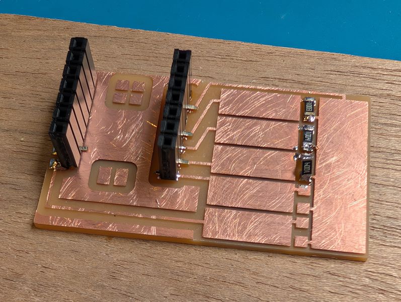
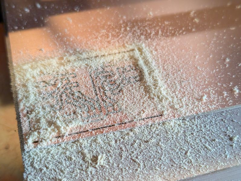
The PCB board has been cut. I attached parts. This time, only for sockets.
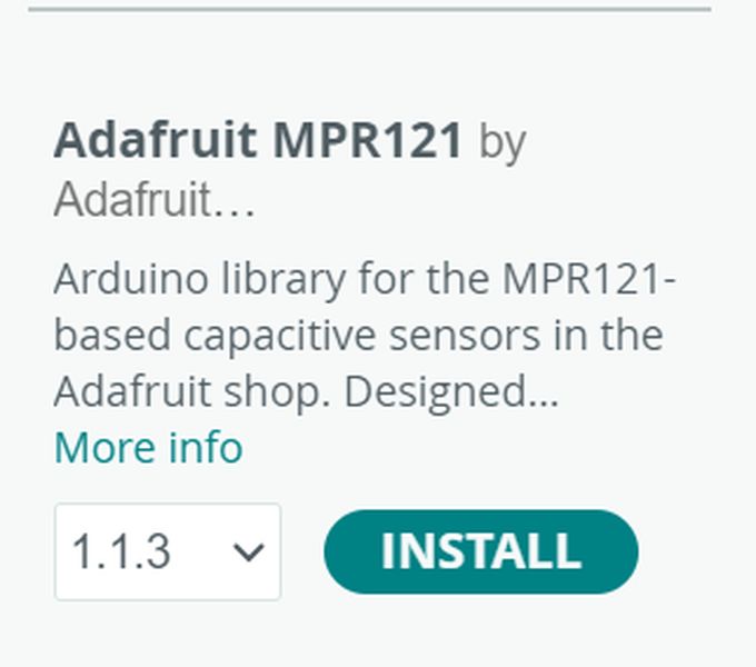
Install the library
Next, to use the MPR121, you need to install the library in Arduino. I installed the following:
After adding the library, I found test code for MPR121, so I tried that.
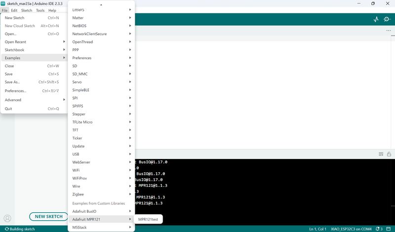
The sample code is as follows:
/*********************************************************
This is a library for the MPR121 12-channel Capacitive touch sensor

Designed specifically to work with the MPR121 Breakout in the Adafruit shop
  ----> https://www.adafruit.com/products/

These sensors use I2C communicate, at least 2 pins are required
to interface

Adafruit invests time and resources providing this open source code,
please support Adafruit and open-source hardware by purchasing
products from Adafruit!

Written by Limor Fried/Ladyada for Adafruit Industries.
BSD license, all text above must be included in any redistribution
**********************************************************/

#include <Wire.h>
#include "Adafruit_MPR121.h"

#ifndef _BV
#define _BV(bit) (1 << (bit))
#endif

// You can have up to 4 on one i2c bus but one is enough for testing!
Adafruit_MPR121 cap = Adafruit_MPR121();

// Keeps track of the last pins touched
// so we know when buttons are 'released'
uint16_t lasttouched = 0;
uint16_t currtouched = 0;

void setup() {
  Serial.begin(9600);

  while (!Serial) { // needed to keep leonardo/micro from starting too fast!
    delay(10);
  }

  Serial.println("Adafruit MPR121 Capacitive Touch sensor test");

  // Default address is 0x5A, if tied to 3.3V its 0x5B
  // If tied to SDA its 0x5C and if SCL then 0x5D
  if (!cap.begin(0x5A)) {
    Serial.println("MPR121 not found, check wiring?");
    while (1);
  }
  Serial.println("MPR121 found!");
}

void loop() {
  // Get the currently touched pads
  currtouched = cap.touched();

  for (uint8_t i=0; i<12; i++) {
    // it if *is* touched and *wasnt* touched before, alert!
    if ((currtouched & _BV(i)) && !(lasttouched & _BV(i)) ) {
      Serial.print(i); Serial.println(" touched");
    }
    // if it *was* touched and now *isnt*, alert!
    if (!(currtouched & _BV(i)) && (lasttouched & _BV(i)) ) {
      Serial.print(i); Serial.println(" released");
    }
  }

  // reset our state
  lasttouched = currtouched;

  // comment out this line for detailed data from the sensor!
  return;

  // debugging info, what
  Serial.print("\t\t\t\t\t\t\t\t\t\t\t\t\t 0x"); Serial.println(cap.touched(), HEX);
  Serial.print("Filt: ");
  for (uint8_t i=0; i<12; i++) {
    Serial.print(cap.filteredData(i)); Serial.print("\t");
  }
  Serial.println();
  Serial.print("Base: ");
  for (uint8_t i=0; i<12; i++) {
    Serial.print(cap.baselineData(i)); Serial.print("\t");
  }
  Serial.println();

  // put a delay so it isn't overwhelming
  delay(100);
}
When I touched it, I was able to read the reaction well.
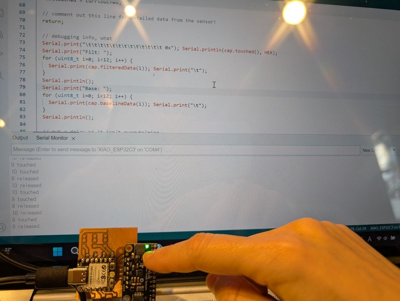
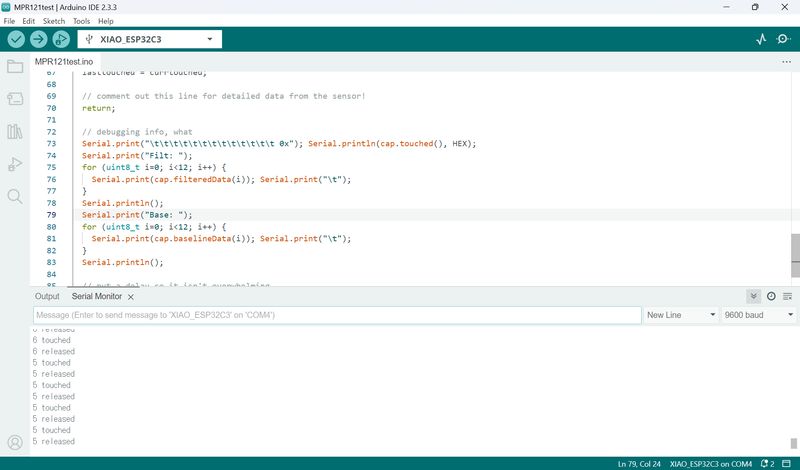
How it works: The MPR121 performs the analog-to-digital conversion.
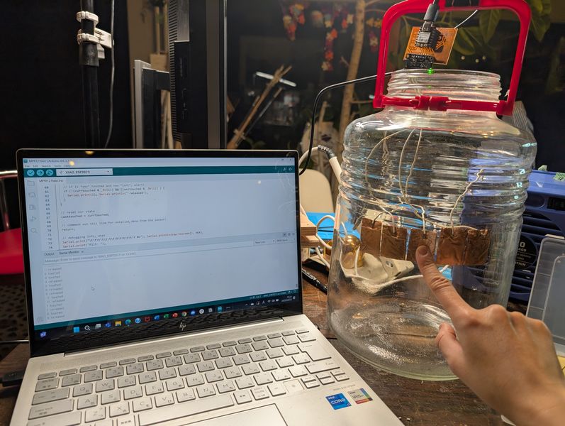
After that, I tried sticking it on glass, but it didn't work...
Maybe the soldering wasn't done properly.
It seems like I need to improve it if I want to actually use it for my Final Project.
Outcomes
I was able to try out a variety of different touches!
However, I still need to refine each one a bit before I can decide which one to try in
Final.
Also, in order to get the output, I need to decipher a little more about each code.