Assignment #3 Computer-Controlled Cutting
This week I learned how to cut materials with lasercutter and vinylcutter.
Assignment
Group Assignment
- Do your lab's safety training
- Characterize your lasercutter's focus, power, speed, rate, kerf, joint clearance and types
Individual Assignment
- Cut something on the vinylcutter
- Design, lasercut, and document a parametric construction kit, Accounting for the lasercutter kerf, which can be assembled in multiple ways, and for extra credit include elements that aren't flat
Outcomes(original design files)
What did I do this week: 1. Group Assignment
The group assignment page - week03
1-1. Do your lab's safety training
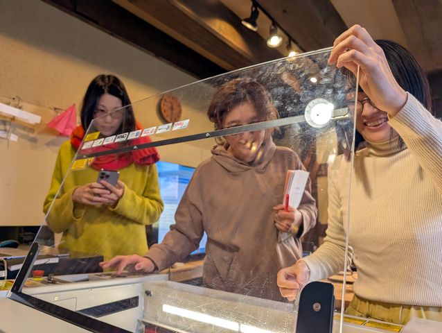
We have got the safety training from Instructors.
- Keep watch the machine and do not go away when you cut something.
- Do not watch directory the light of the laser.
- Open window to avoid toxic gases.
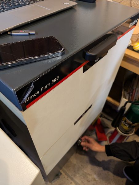
- Check if Laser Exhaust Systems is on while cutting
- In case of emergency, press the physical stop button on the lasercutter and stop cutting.
- When it start burning, and if it is small, you will extinguish fire with rug or blowing.
- If the fire get large, use fire extinguisher which is set next to the lasercutter.
- Be careful to open the lid when it is burning, so that the flame get oxygen and larger.
- Do not put the water to the machine.
1-2. Characterize your lasercutter's focus, power, speed, rate, kerf, joint clearance and types
First, we learned basics of Material
Processing.
Subtractive/Additive
- Subtractive: Nice to make the most of the material. e.g., cutting, Molding, etc…
- Additive: add materials. e.g., 3d printers
There are some kinds of lasercutter.
- CO2 (lasercutter in FabLab Kamakura is CO2 type. It is cheap, but it cannot cut metal, and metal can fly off, so be careful not to put metals.)
- Diode (Used for CD Recorder. It's becoming more common these days, and metal can be also cut.)
- Fiber (metal can be cut. Shoot Stone)
- Yag (For cosmetic surgery, etc. Easily absorbed by the skin.)
The Lasercutter works by using a lens to focus, similar to how a magnifying glass
causes paper to burn when focused.
Vector and Raster
- Vector:Cutting (lines)
- Raster:Etching (Take long time/ Shading)
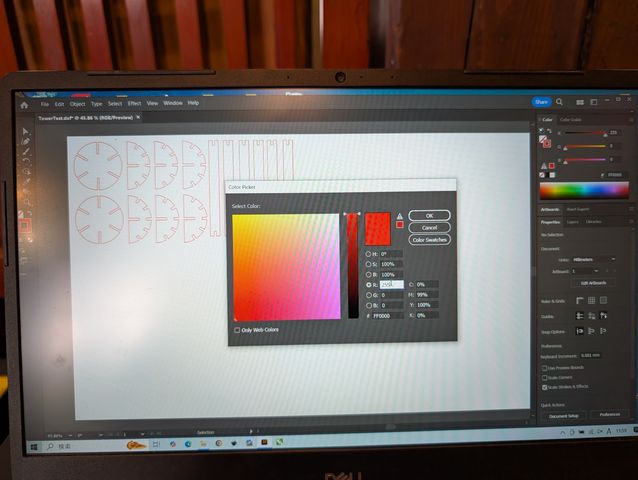
Setting in Illustrator to use a lasercutter
- Vector:Red (R=255, G,B=0) 0.001mm set manually
- Raster:Black
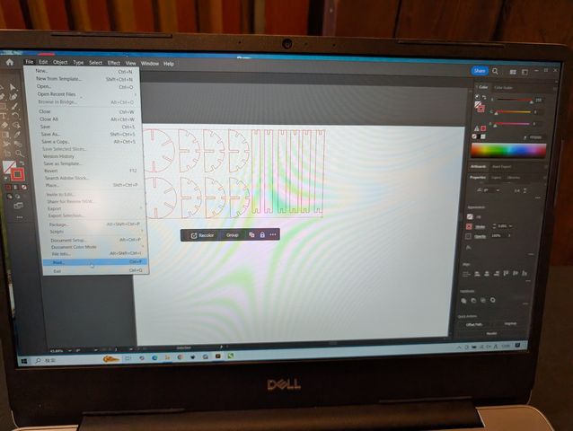
Check to Ignore artboard
Go Print > Select Trotec
1-2-1.Characterize the lasercutter's focus, power, speed, rate.
Now time to use it.
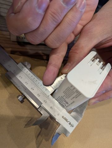
Before you make the data on the PC, first, measure the thickness of the
material!
(There may be discrepancies with the product description.)
So, we started for measure the thickness of the cardboard with a Caliper.
It seems the cardboard is exactly 3.0mm.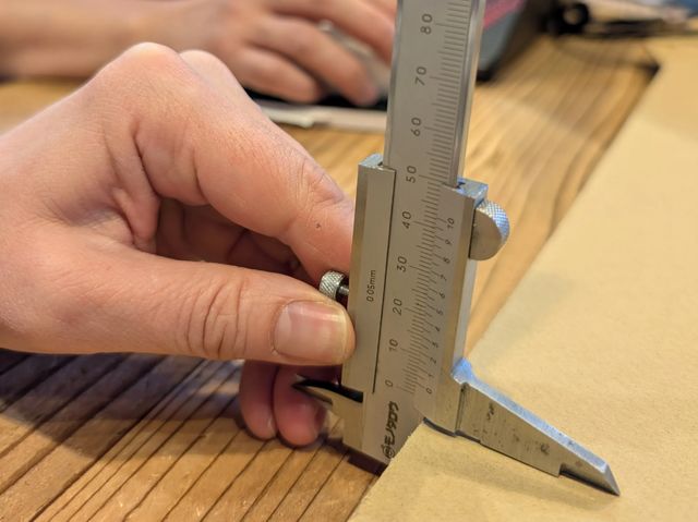
*We can use a
Caliper in 3 way.
- Grab the material
- distance between objects (e.g., inside of a bottle cap)
- Measure depth
If the 0 is not in the exact position, look for the exact digit, and that exact position is the result of the scale.

Then, as for Characterize the lasercutter, firstly, we want to know focus, power,
speed, rate, so that we can also mesure the kerf and joint clearance with that
output settings.
Then, make a rectangle data and print it with various
power/speed.
We found power:35 and speed: 120 seems nice.
For the detail of our works, please see here: Group
Assignment page.
1-2-2 Characterize lasercutter's kerf, clearance
We use the Kerf
Check Parts Generator by Mr.Daisuke Doyo in FabAcademy
2018(Kamakura).
This time I prepare the data for print this tool.
Since the thickness is 3mm, “start” is 3mm.
I tried to change some parameters for “pitch”.
And finally, the setting below might be good for testing.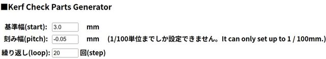
The output data(kerf_check_final.svg) is as
shown: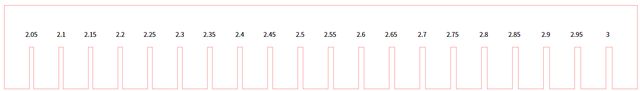
We cut it out and found 2.55-2.65mm seems
nice.
We confused about “what is the difference
between
kerf and joint clearance?”
And this is what we have learned.
- Kerf: Width of the material burned away by the width of the laser beam
- Joint Clearance: To allows the connection to be made smoothly (=Tightness)
And the difference between the cardboard thickness and the dimension(in data) is 0.3mm (3.0mm - 2.7mm), this is the joint clearance.
For the detail of our works, please see here: Group Assignment page.
What did I do this week: 2. Individual Assignment
2-1. Cut something on the vinylcutter
Create vector data in Inkscape
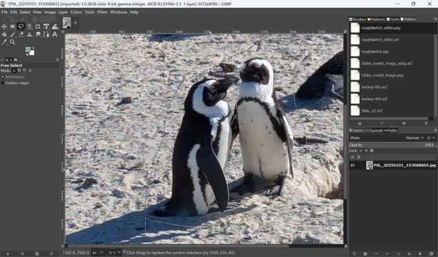
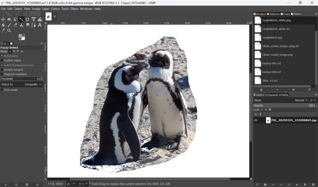
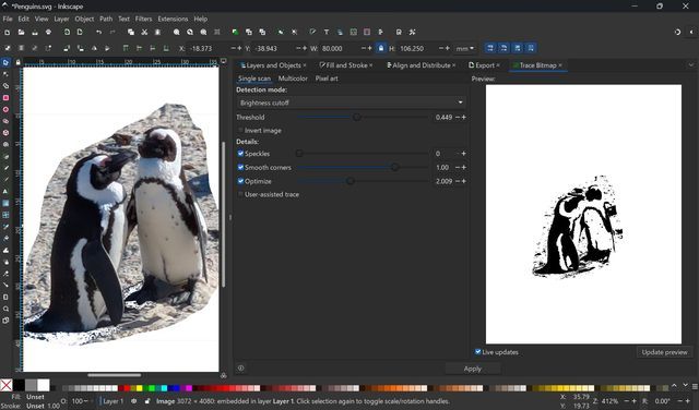
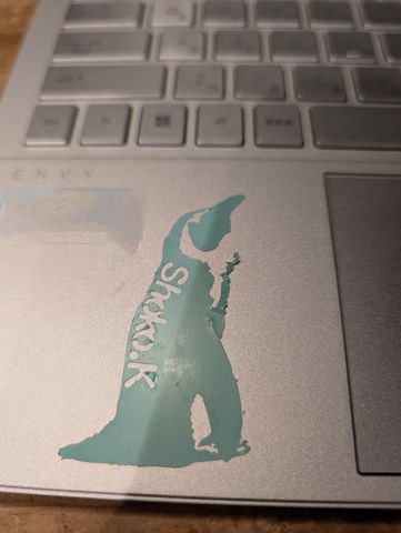
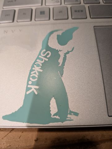
I tried to make a seal from a photo I took recently in South Africa.
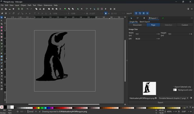
First, I
want to cut the unnecessary parts of the photo. Select the parts you want to use
with Free select tool, and Quick Mask. Then, delete shade to make their foot
clearly shown. Then, export file as PNG.
Use Free select
tool (same as week 2)
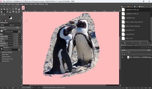
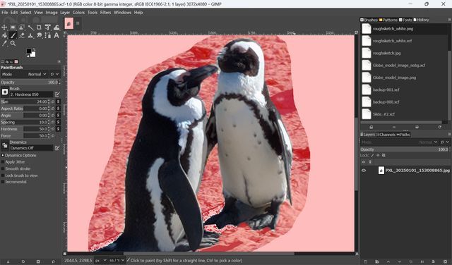
(After 1st trial, I also used Quick Mask. Choose Quick Mask ****and paint the place you don’t need with a brush tool.)
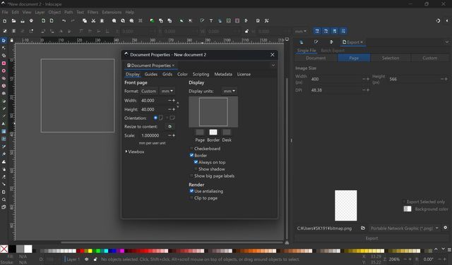
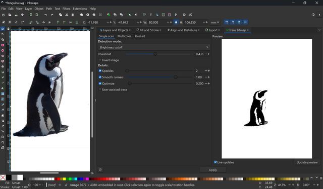
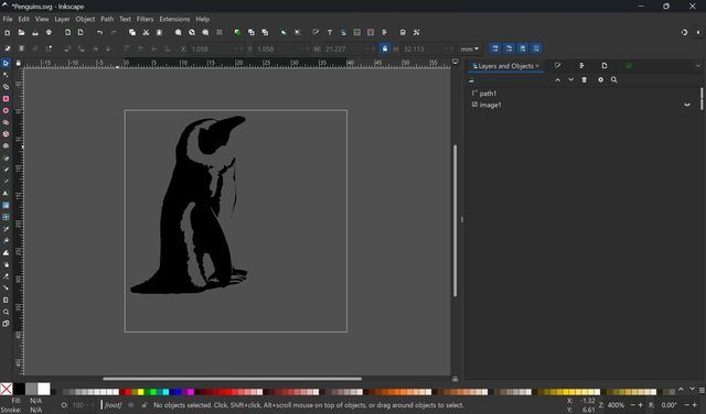
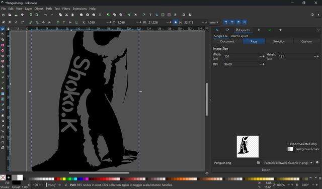
In Inkscape, I made a file 20mm x 20mm. Then, Import the Photo(SVG file I made). It seems the image size of the photo is too big, so I shrink it fit to the canvas size.
Then, change the style of photo to cut it. First, select “Trace Bitmap”, and change Threshold.
Delete unnecessary path (I modified the original image with Quick Mask)
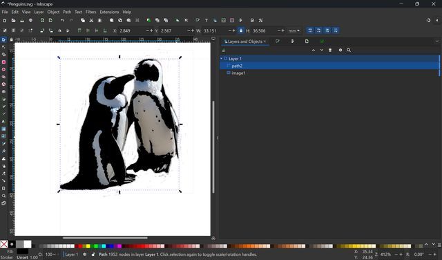
To make as seal, just 1 penguins may be better. So I deleted paths for one penguin.
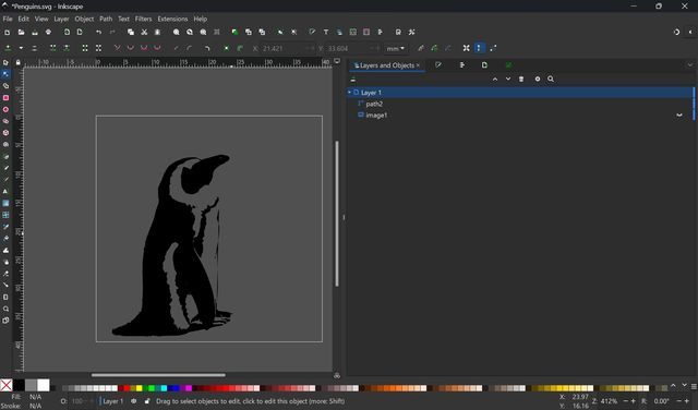
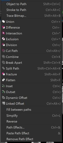
Delete some unnecessary parts and make it simple with path tool.
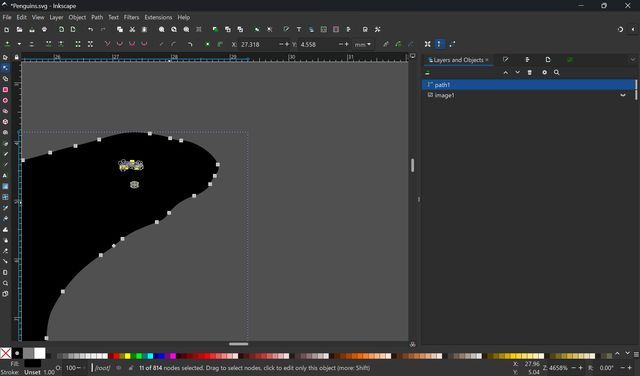
Adjusted some path to make the line clear
I want to add my name on the backside of the penguin with text on path tool.
Draw the path fit to the backside of the penguin with path tool, and also write my name with text tool. I changed font.
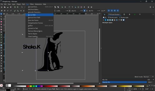
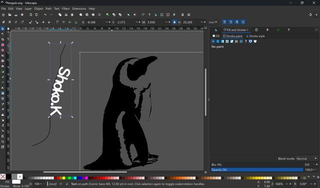
Make text to path to print it. Move the the back side of the penguin. Then, choose both penguin and text, and select “Difference” to make the text as a hole.

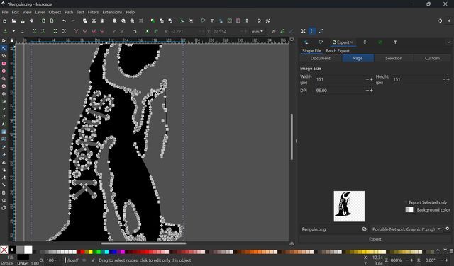
Since I want to keep the o shape(don’t want to cut as a big hole), I added a new shape and Union with the penguin.
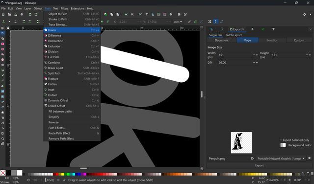
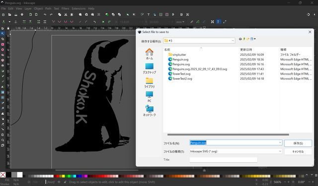
Save as svg.
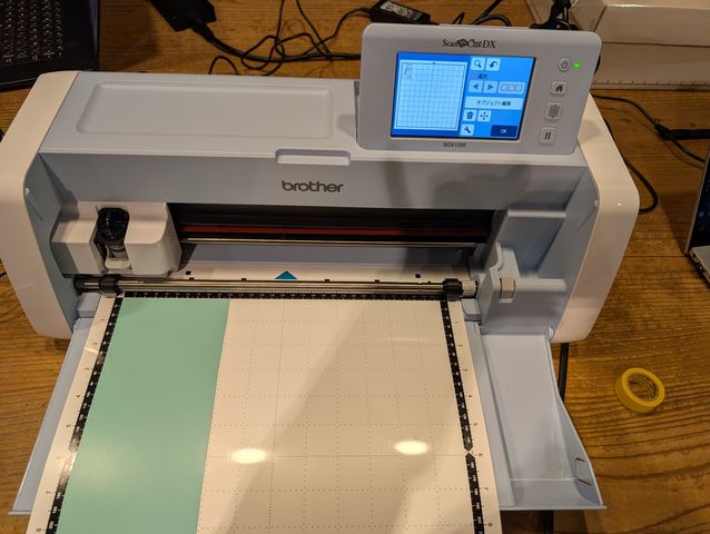
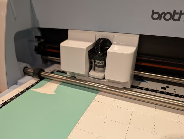
Vinyl Cutting machine
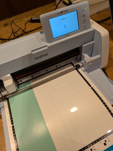
Then, Start the Vinyl Cutting machine.
I used Brother SDX1200.
Insert the sheet with the insert button. When you cut something, we have to use
adhesive sheet to fix the material. Be careful, when you cut the paper, we must
use the weak one…the paper will remain on the strong one, and will become
unusable.
Then, read the data on the Vinyl Cutting machine. Since the data seems a bit small, I fixed it.
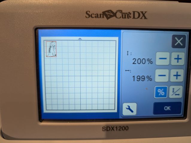
Press OK, and start cutting. It seems the cutting power is too strong, and the data is still too small.
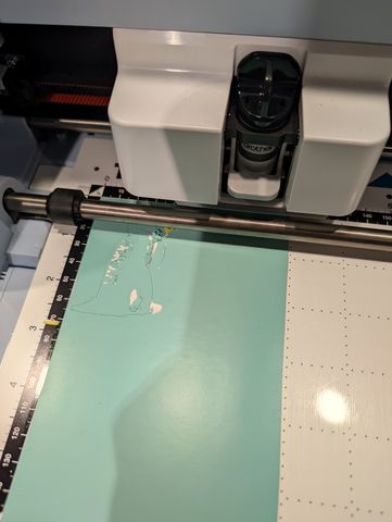
Now, it seems better. The outline seems too thin and couldn’t cut.
The data is here.
2-2. Design, lasercut, and document a parametric construction kit, Accounting for the lasercutter kerf, which can be assembled in multiple ways, and for extra credit include elements that aren't flat
I did the assignment with follow steps.
Research
First, I searched the sample of product with “Parametric Design”
I found some cute animals, and am interested in how to make them.
Parametric
Hedgehog
Parametric
Horse
Parametric
Camel
Then, with recommendation form Kae-san and Rico-san, I learned what is
“Parametric Design” and how to realize them with some tutorial on
Youtube.
https://www.youtube.com/watch?v=2rJf8ELAkcQ
https://www.youtube.com/watch?v=nNVzv8BgxzQ
https://www.youtube.com/watch?v=yr3Ff8RxZH4
https://www.youtube.com/watch?v=-hgsqjT98jo
https://www.youtube.com/watch?v=dWYMBVTUvDA
https://www.youtube.com/watch?v=JGRV0PVCB_M&t=26s
Then,
first, I tried to make some simple parametric parts to assemble if it works.
(1st Modeling)
After this, first, I tried to model
animal. However, it seems tough to model animals and make it sliced… how can
I
make parametric…?
Also, I have got some feedback that it would be better if it could be
assembled in different ways. How to make animals changeable…Baby and
Parents…?
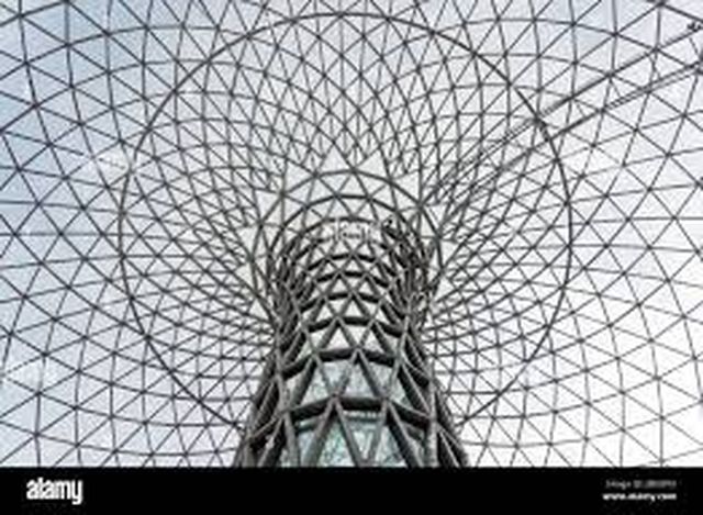
So, I also searched to the images with building.
Hmm… This building looks interesting. Tokyo tower is also made from some
rods. I also remember the tower near my university…
Let’s try to make something like this…connect rod in different ways and make
some shape with triangle and more.(2nd Modeling)
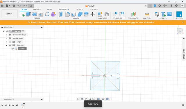
First Modeling(Test)
First, just make a simple shape to try assembling.
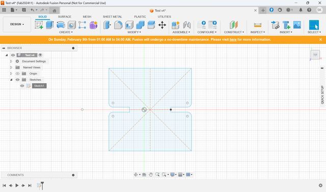
I chose a rectangle. Create
Sketch and make rectangle.(You can choose rectangle whatever you like.)
Then,
I add small rectangle as a slot parts.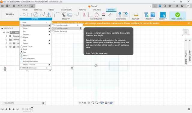
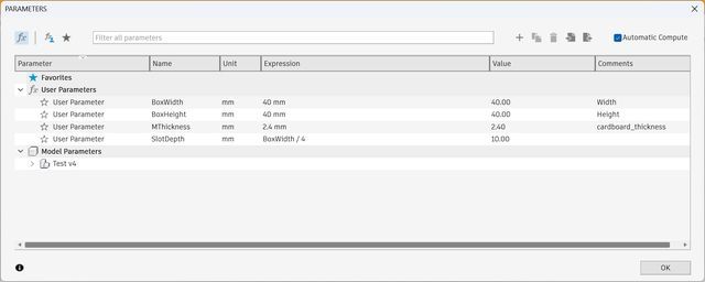
Then, set Parameters. Go
to
“Modify” menu and choose
“Change Parameters” menu.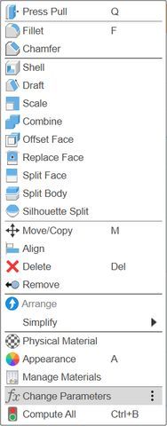
Then, add parameter from
plus button next to filter
window.
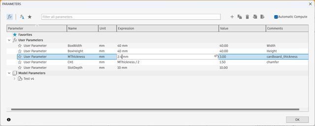
Add name(for parameter name easy to understand), Expression(the
number you want to set), and add detailed Comment if you need. I set width and
height as 50mm this time.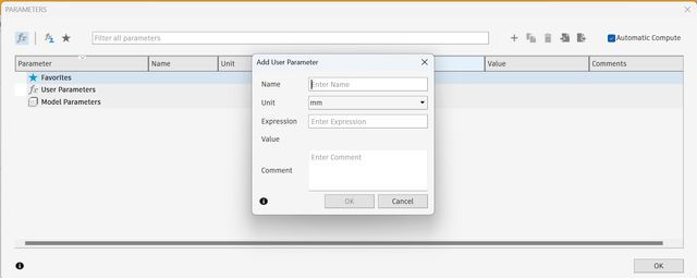
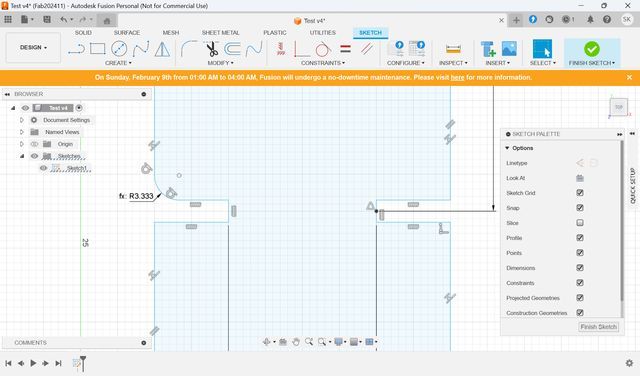
Then adapt the perimeter
to the lines.
Select “Sketch
Dimension” and choose the edge you want. Then, type name of parameter, not the
number, to the box and you can set the parameter to the edge.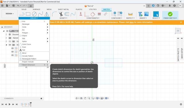
Then I
made some mistakes this
time.
- We have to set parameter in “Sketch” mode.
- All Rectangles should on the same sketch.
So, I back to the first sketch step, and add all boxes/materials I need.
You
can change parameters from ”Modify” when you are in sketch mode.
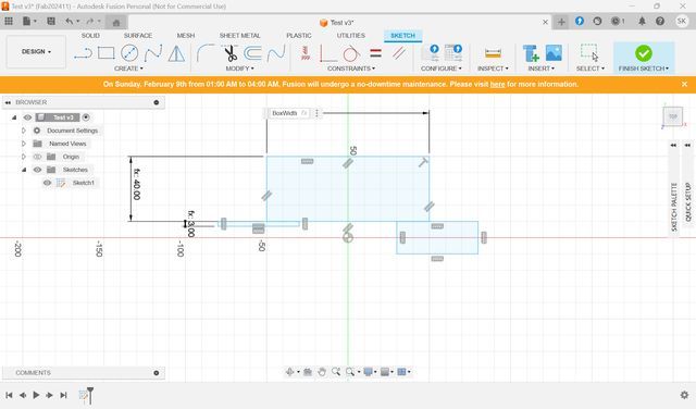
I
set/add/fixed some parameters.
We have found that it is good to set
thickness 2.5 for the material cardboard with the lasercutter in FabLab
Kamakura as I mentioned above, and I wanted to try chamfer, so I
set the thickness as 2.4mm.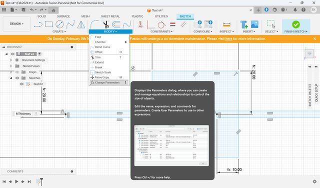
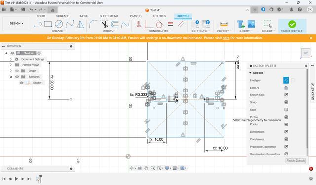
Then, set the parameter to
the edges. Set slot depth
also.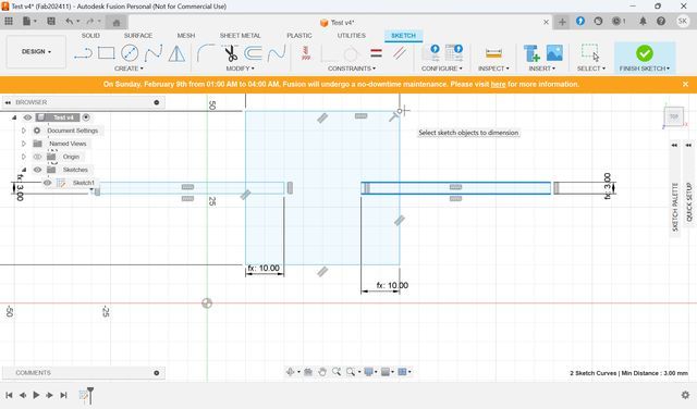
Also,
there are some shortcuts:
Press D : Sketch
Dimension
+Press Shift : choose middle of the parts
I want to set the slot
middle of the rectangle, so I press D + Shift, and Select Middle of the
path.
↓The X mark means the middle of the line, and it show up when you press
shift.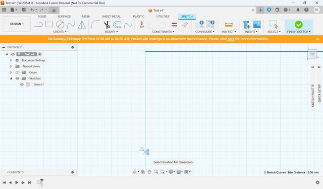

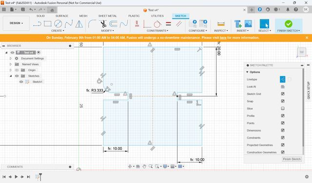
All parameters
are set.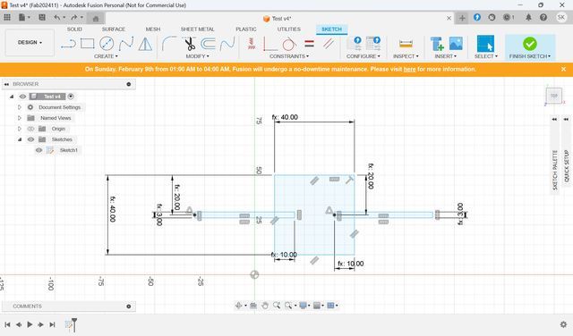
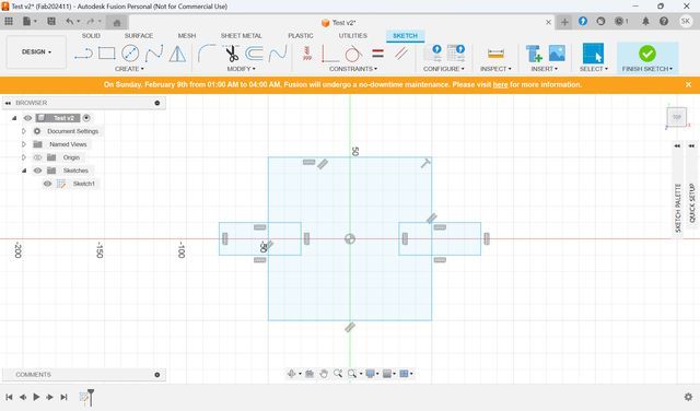
Then, choose Trim and cut unnecessary part.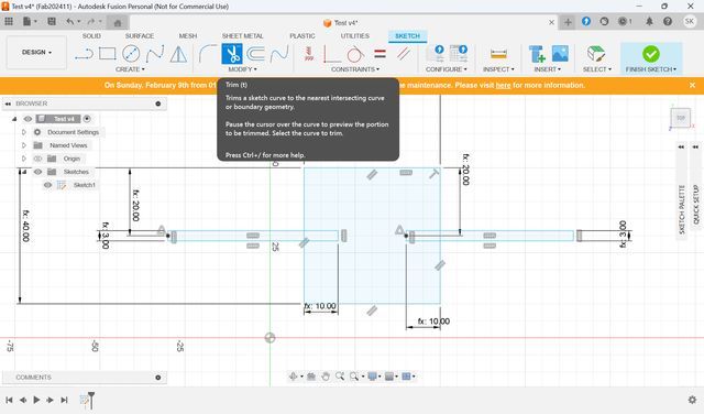
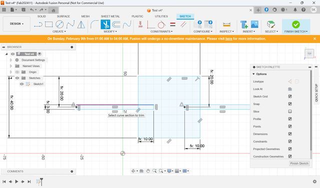
The
shape
was
made.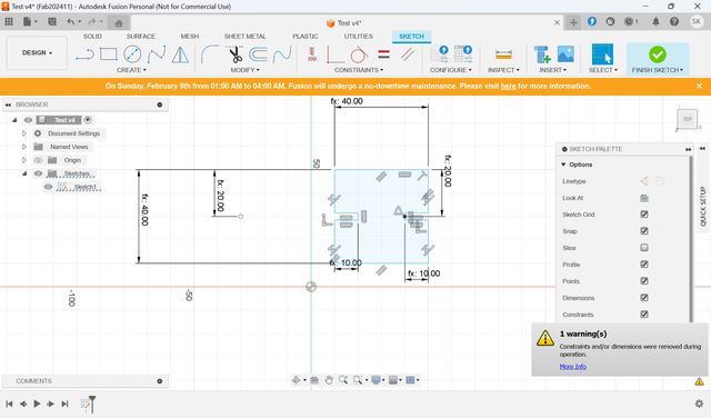
As
I
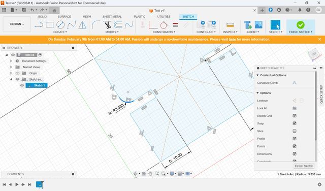
mentioned above, to try make Chamfer, Choose Filet
and select the point you want to add them. Then, set parameter.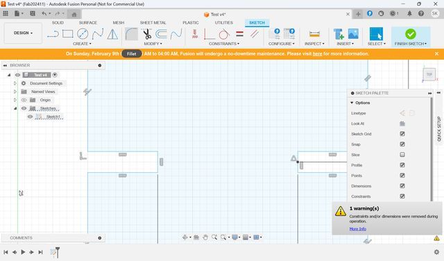
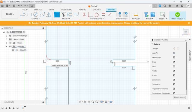
I want
to
mirror it, so add lines,
and make it as
“Construction”. The line turns to dotted and it won’t be cut.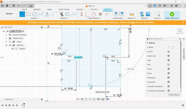
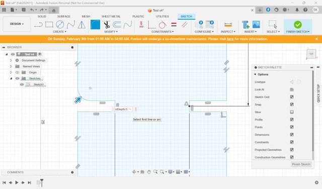
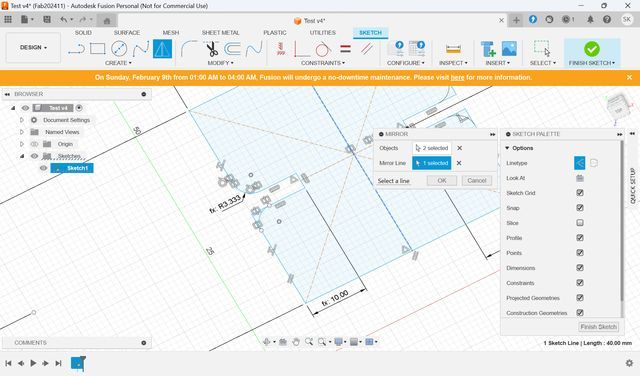
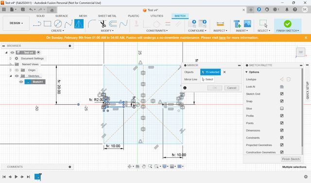
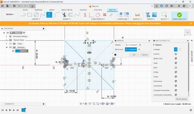
Let’s
Mirror the
hinge.
Select
mirror from create
menu. Set “Object” what you want to mirror and set “Mirror Line” as what you
want to reflect it.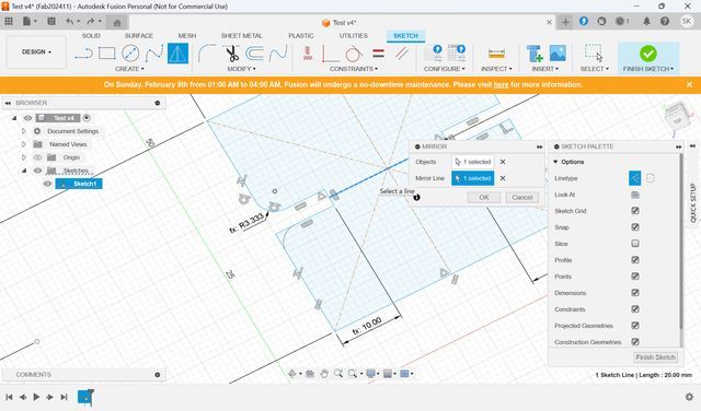
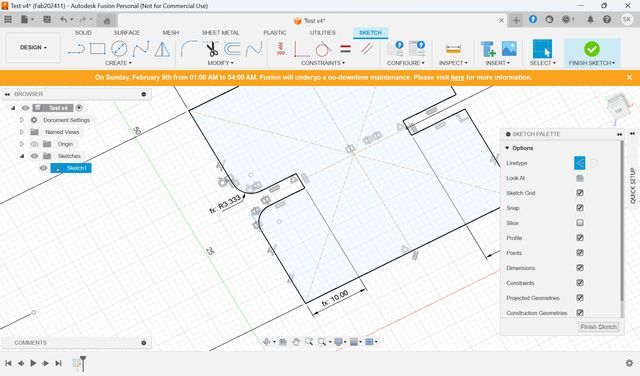
Press OK. Mirrored. Then, mirror to another
side.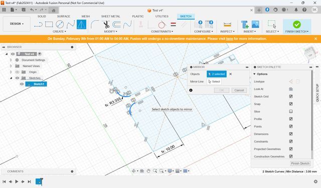
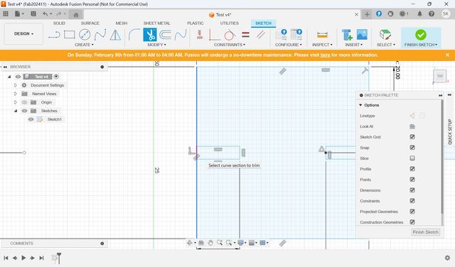
Trim unnecessary
lines.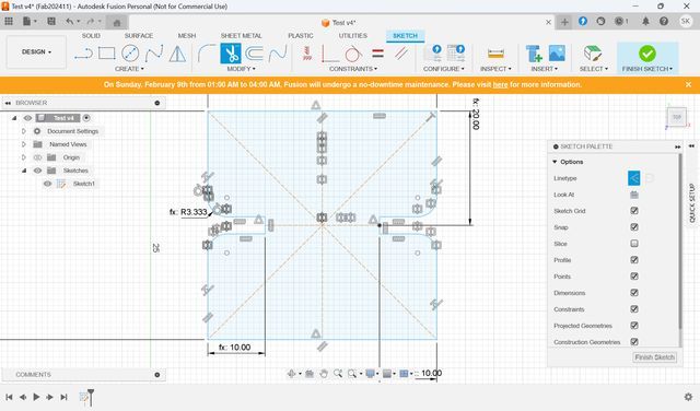
https://www.notion.so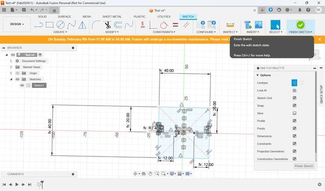
Save as DXF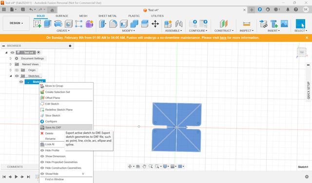
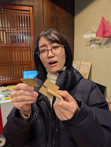
I
cut
them
out and tried to assemble.
(The way of printing will be described later)
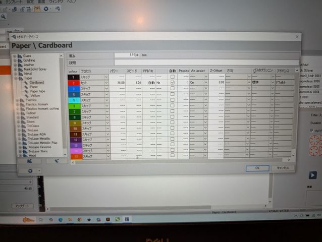
The printer settings are as shown ... power: 36.00 / speed: 1.20
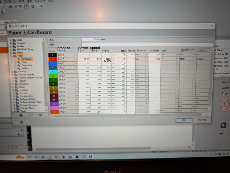
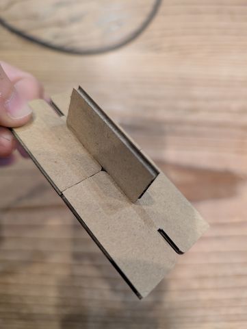
It seems ‘Slot Depth’ is too much and doesn’t fit.
So I reduced it as 1/4 of width(It might be changed to height if the width is longer than height)
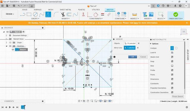
I also want to add slots to upside and downside. So I mirror them.
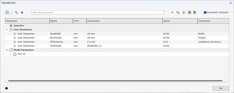
| Name | Unit | Expression | Value |
|---|---|---|---|
| BoxWidth | mm | 40mm | 40.00 |
| BoxHeight | mm | 40mm | 40.00 |
| MThickness | mm | 2.4mm | 2.40 |
| SlotDepth | mm | BoxWidth / 4 | 10 |
The data is here.
Second Modeling
To make the tower, all I need is rod and connection parts.
Connection parts is
a bit tricky. I want to make it to be attached from each angles, so I make it in
a ball shape. So that I can make triangle or rectangle with rods!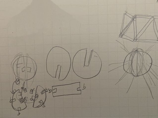
To
make rod
parts, I can use the
model 1, and make it a bit longer.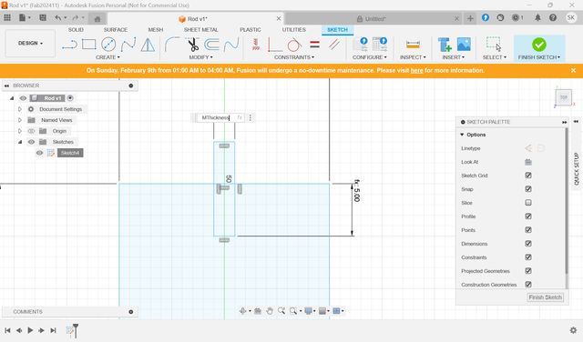
Finish made rod.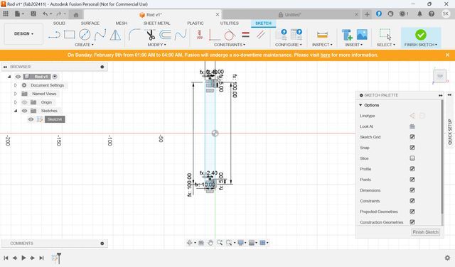
Then,
make
connection parts.
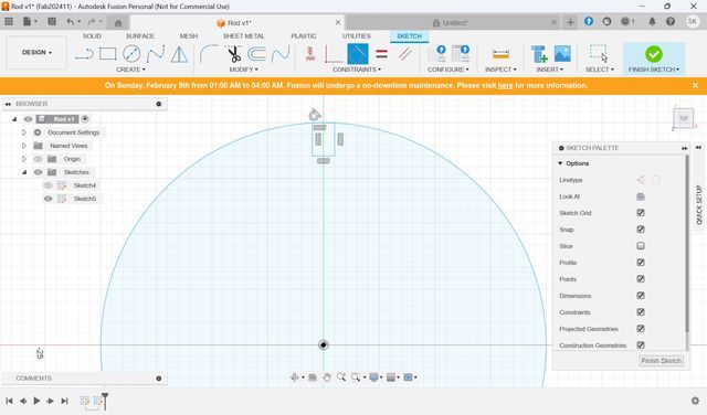
To make
a ball, I need to make “a full circle” and “half circles” to connect circle as a
ball.
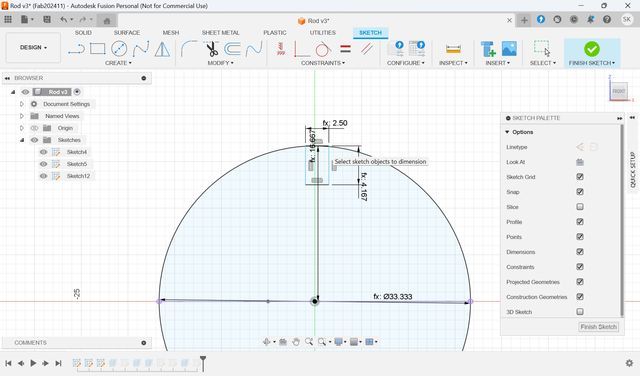
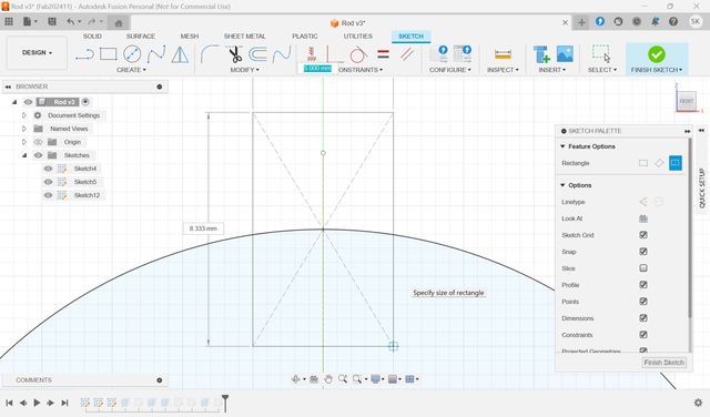
First, make full circle. Then, add a rectangle to make
concave.
Select edge of the concave part, and select “Target”, and fit the
vertices and the edge.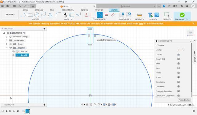
Set depth with parameter.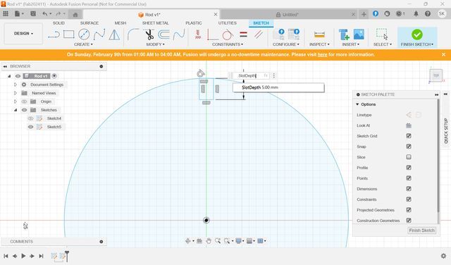
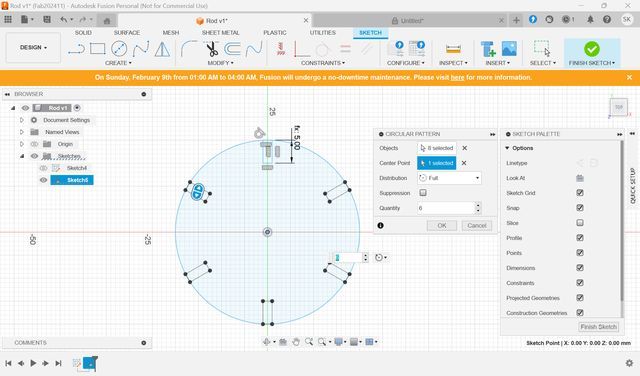
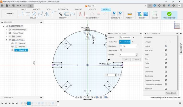
Then, chose “Circular
Pattern”
to
copy/add this concave
to all over the circle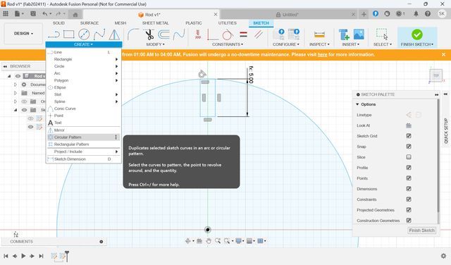
Choose the concave part as “Objects” and select center
of the circle for “Center Point”. Set Quantity as 6.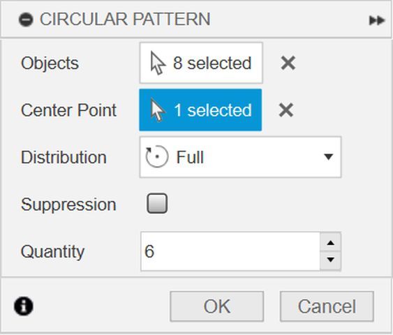
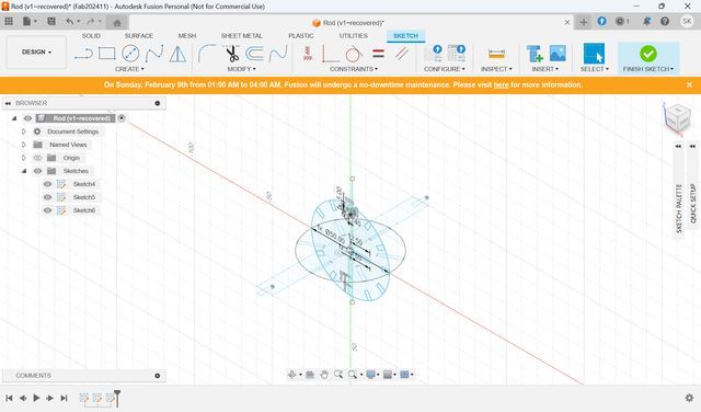
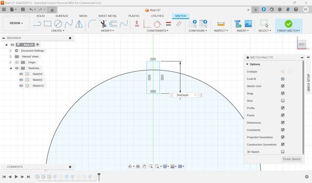
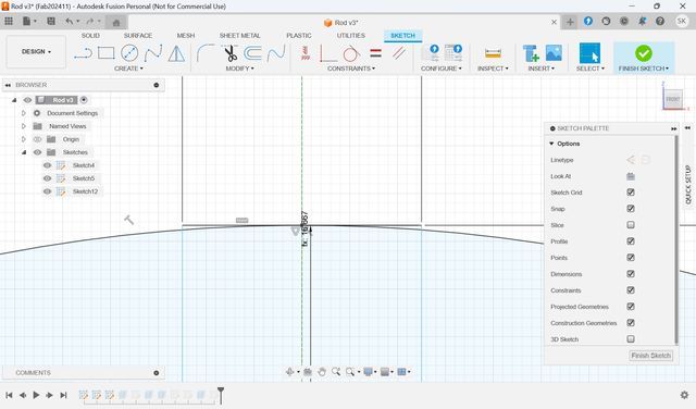
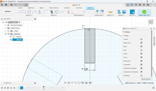
Next, make half
circles.
Create
new sketch in x-z
direction and add 2-point circle.
Same way to add concave part.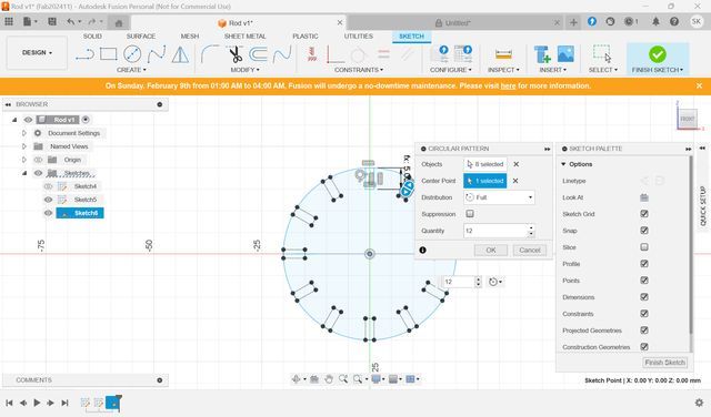
Then,
make
this circle half. Make
the box longer to cut
the circle consider margin. Then, delete unnecessary parts.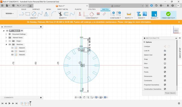
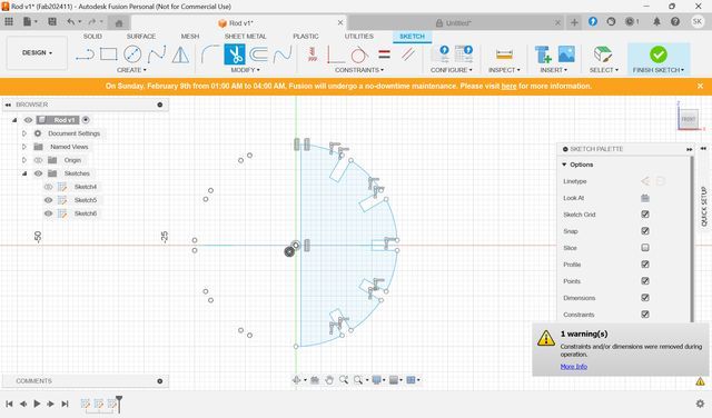
I
deleted some unnecessary
parts,
and something went
wrong. So, modified some shapes/parameters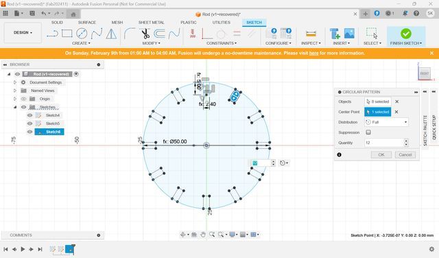
Save as DXF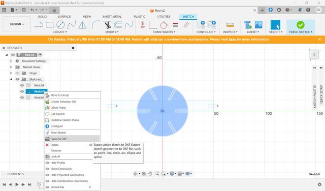
Since I
don’t
want to delete unnecessary parts to modify
them later, I learned the “Object”
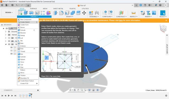
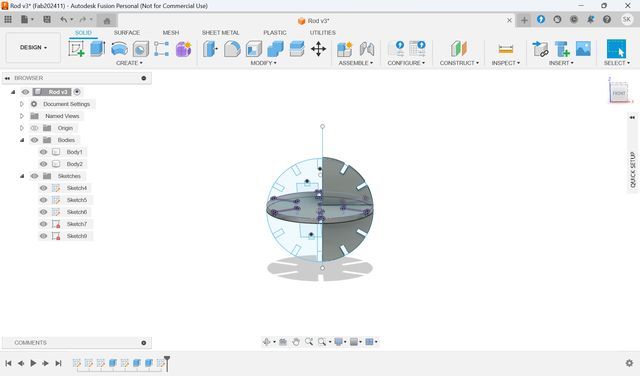
First, Exclude the shape from Crate
Sketch>Exclude.
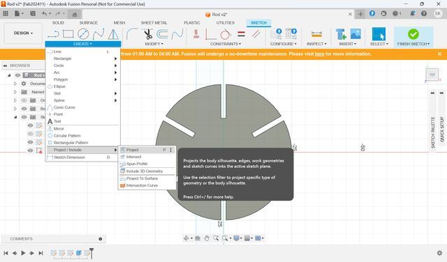
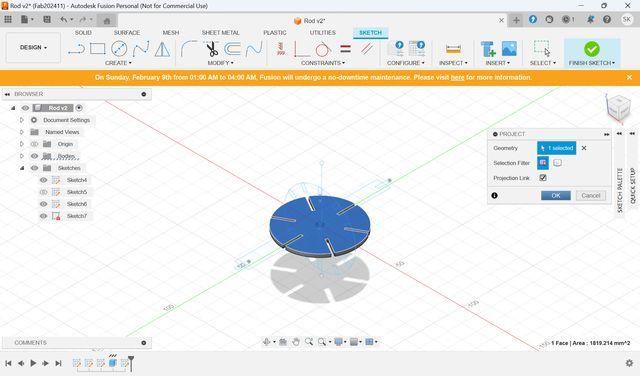
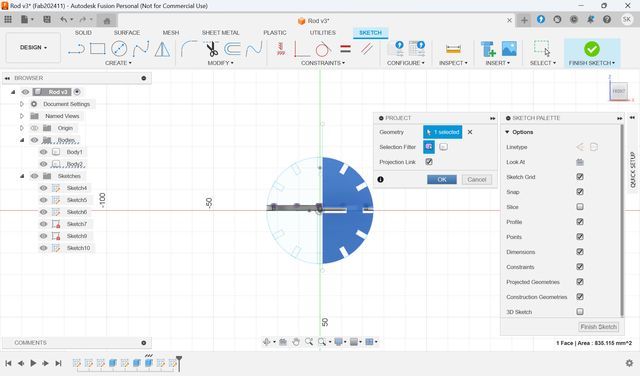
Then select “Project” from create menu. Select the surface you want to export as
“Geometry”, and press OK. Then, select the Sketch newly made from the left side
menu and export to DXF. (You can export only when you are in the Sketch
mode.)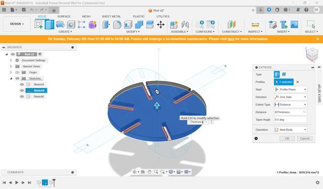
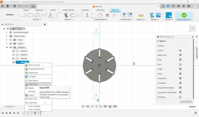
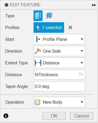
Choose another
surface, and do the same. Be careful not
joint to other parts when you exclude the sketch. Choose “New body” in
“Operation” menu in Exclude.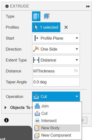
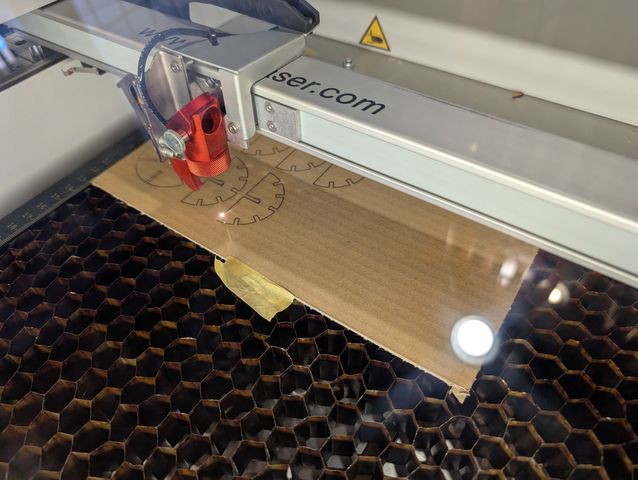
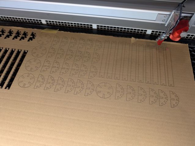
Then, let’s print them
out.
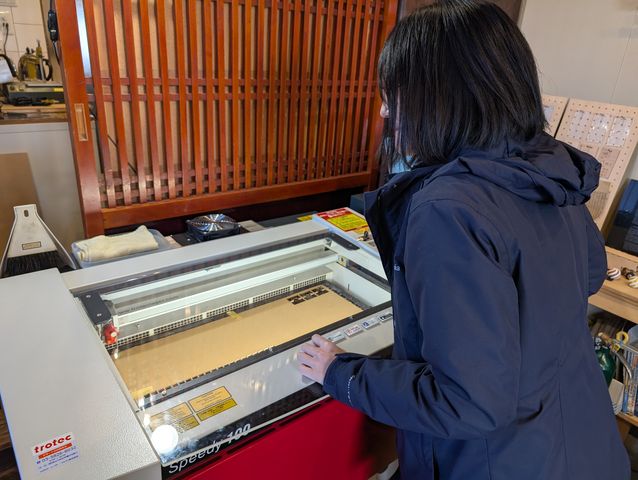
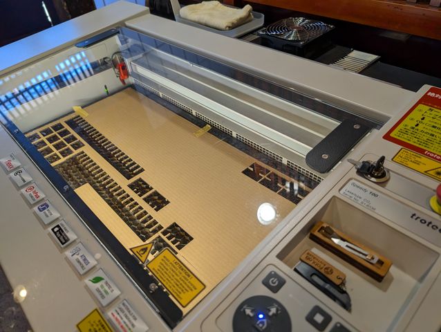
How to cut with laser cutter
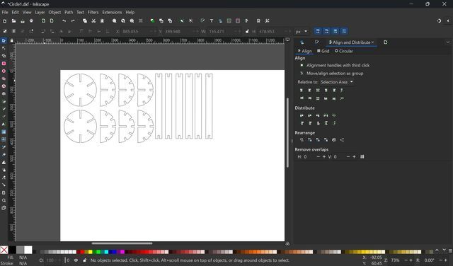
*In FabLab Kamakura, we use Trotec Speedy 100Open Inkscape and set width and height same as the cardboard.
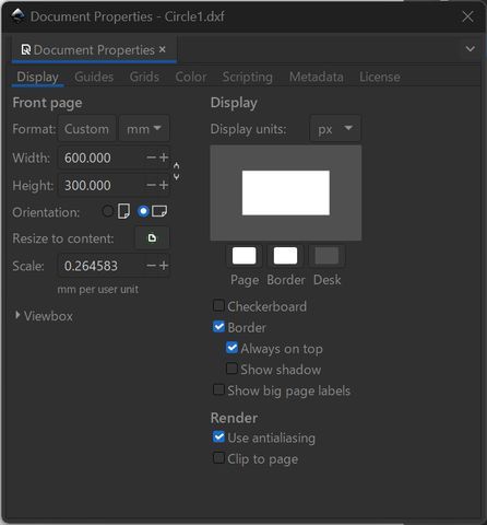
Put the elements and arrange them on the canvas.
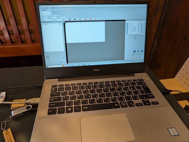
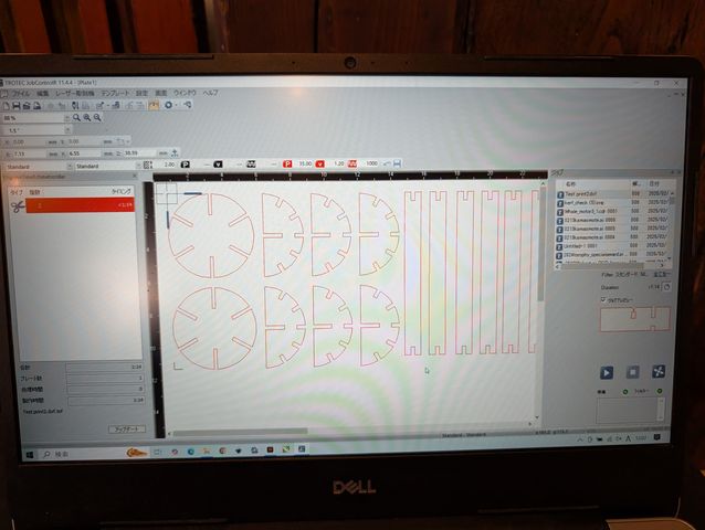
Then, open the data on the Illustrator which is in the pc connected to the lasercutter.
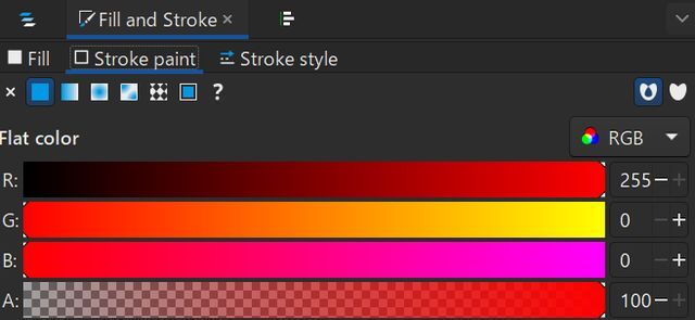
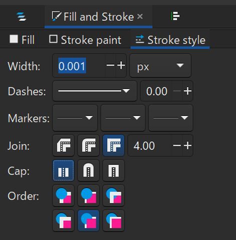
Set the color R:255,G:0,B:0, and line width to 0.001px.
Then, select “print.”
Set Printer as “Trotec Engraver”. Check “Ignore Artbords” Then, press “print”
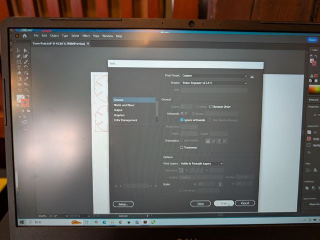
Trotec automatically open.
First, we have to set up the lasercutter.
Before cutting, we have to check if Laser Exhaust System is on.
Then, switch on, and adjust the focal length. move the pointer to the place you want to start print.
Then, connect to the computer.
On Trotec, press connection mark right blow side of the window, and when it is connected, the laser point show up on the middle canvas on the window.
Then, choose the file you want to print from job files on right side.
Then, set the power and speed. Click somewhere on the canvas.
This is the numbers we found suitable for the cardboard this time:
Power:36.00, and Speed:1.20.
Press OK. Then, start print with press play button right side.
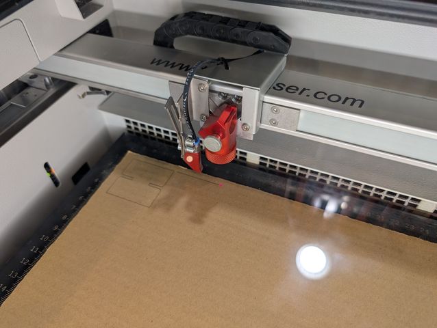
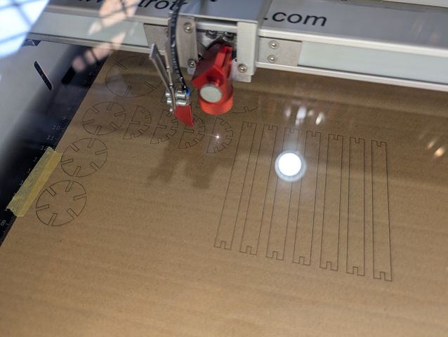
I tried to print them out.
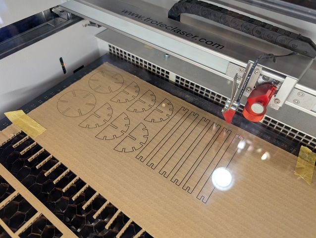
However, it wasn’t cut well. Maybe the cardboard is warped.
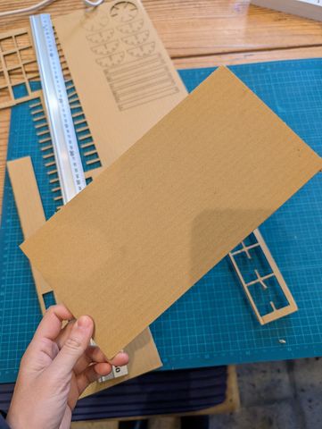
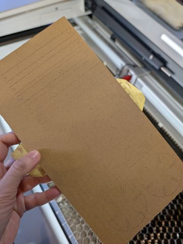
So I tried to cut it as fit to the print area.
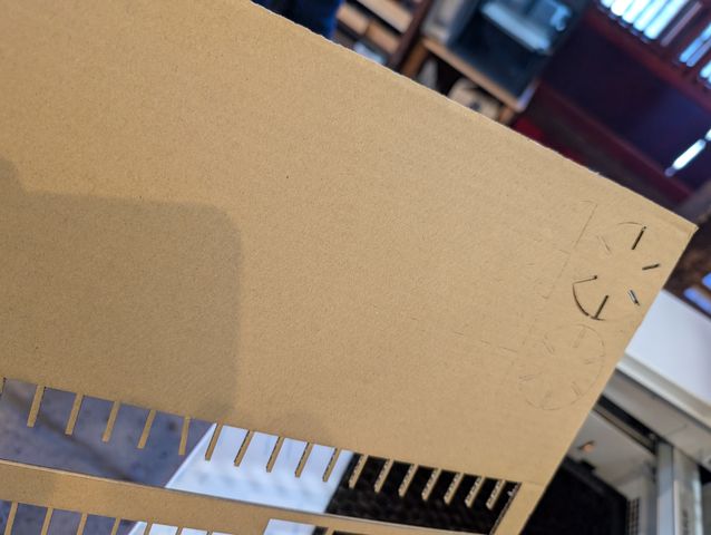
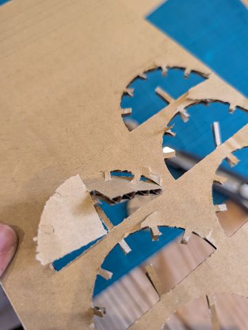
This time the cut line is a bit clear. However, it is still not enough cut. The parts was broken when I took them out from the board. Next time I tried to care about focus point…
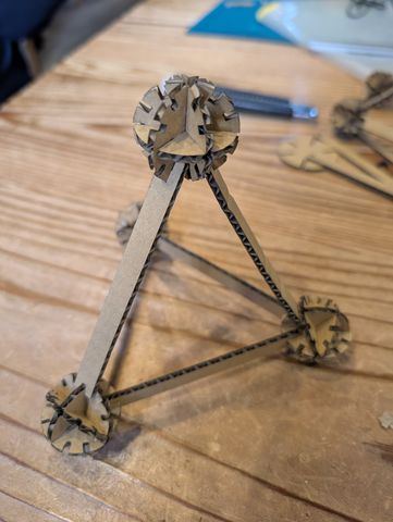
I tried to construct something, but it seems a bit different from what I imaged. The ball part is too big. So I tried to fix it.
I changed some parameters: Make slot Depth fit to Radius(not from rod width)
Something went wrong with Sketch 6(for “half circle”), so I make it again.
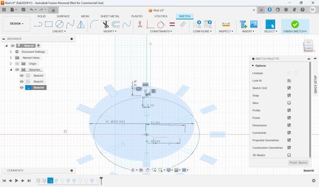
I tried to attach the center of edge of rectangle to the edge of the circle.
It seems not smart way to fit the rectangle center to the circle edge, so I make the rectangle again with “Center Rectangle” (Before that, I added the center line for the circle with line type “Construction”)
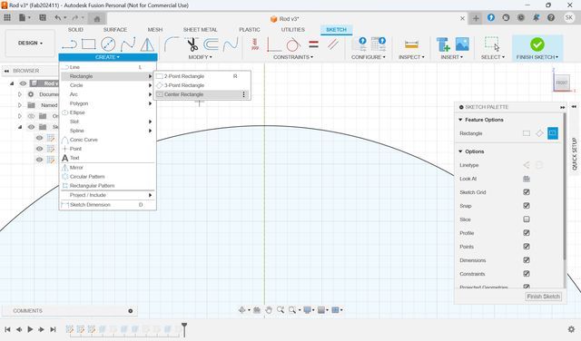
Be careful not to set rectangle center as circumference. It makes impossible to remove rectangle center point from circumference…
Again, circular pattern.
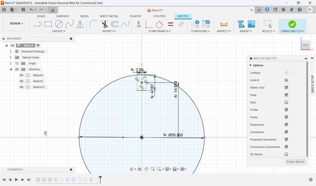
Set parameters.
Then, I noticed, depth of “full circle” is not fixed.. so I also modified them.
Set Point and Move to fit to the center line I added.
Then, same as first trial, I modified the data on Inkscape, and Illustrator, and print it with lasercutter.
First, tried with small amount, and seems nice. Then add some parts.
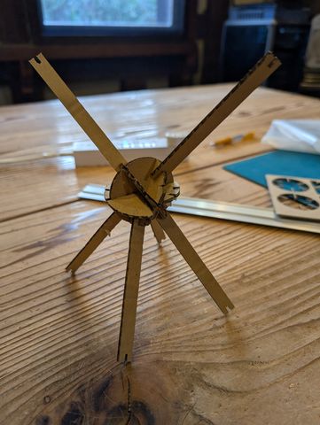
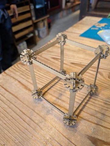
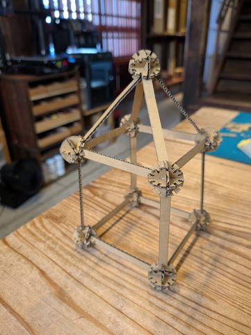
Finally, I constructed some shapes with balls and rods.
It may better to add 45° dent for “full circle”, so that I can make the shape more.
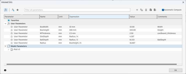
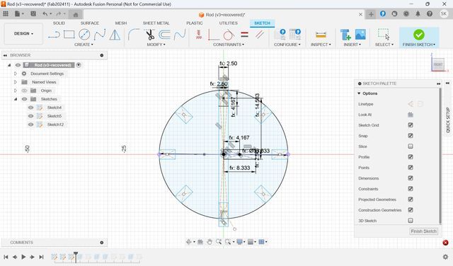
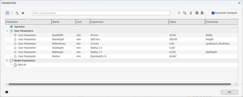
| Name | Unit | Expression | Value |
|---|---|---|---|
| BoxWidth | mm | 10mm | 10.00 |
| BoxHeight | mm | 100mm | 100.00 |
| MThickness | mm | 2.5mm | 2.50 |
| SlotDepth | mm | Radius / 4 | 4.167 |
| BallDepth | mm | Radius / 2 | 8.333 |
| Radius | mm | BoxHeight / 6 | 16.667 |
Outcomes(original design files)
- Data for vinylcutter
- Penguin_Final.svg (for cutting)
- PenguinPicture.xcf (material)
- Data for lasercutter
- CostructionKitFinal.f3d (model2)
- Model1_AssembleTest_v5.f3d (model1)
It was really fun. but tough to think quick and output something in real world.
Also, to make the data real, we have to consider the material condition, or
temperature, humid, and many conditions that cannot be determined with computer.
I am still trying to create and print the parametric animal construction kit…and
I would like to make it finish!
*This page uses Google Translate to translate
some sentences(Especially for group assignment part).