#7 Computer-Controlled Machining
This week I learned how to use CAM, and big scale production.
Assignment
Group assignment
- Complete your lab's safety training
- Test runout, alignment, fixturing, speeds, feeds, materials and toolpaths for your machine
Individual assignment
Outcomes
What did I do this week: 1. Group Assignment
The group assignment page - week07
Complete your lab's safety training
Test runout, alignment, fixturing, speeds, feeds,
materials and toolpaths for your machine
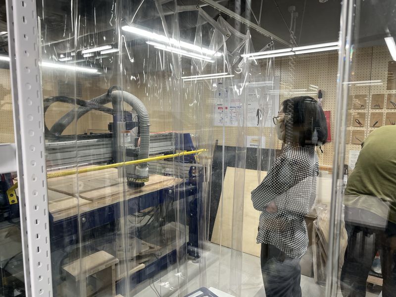
This week, we tested the settings for Shopbot in
FabLab Minatomirai.
Note for me: For safety… (Especially important)
- Check the stop button before start cutting
- Stay close to the machine (at a safe distance) while it is cutting to make sure everything is OK
- Use Vacuum to avoid dust accumulates and ignites
What did I do this week: 2. Individual assignment
Make (design+mill+assemble) something big
Procedure
In class, we learned the steps of Computer-Controlled Machining as follows:
- Choose Machine
- Choose Material (Be care about check size and thickness)
- Tooling
- Set speeds and feeds
Planning
There is a favorite chair in the co-working space I often use (this is also the venue for the Fab Quest program by FabLab Kamakura) and I wanted to have one. However, there is a problem with the chair, so I have not yet purchased it. It is that it cannot be disassembled into smaller pieces. I am still planning on moving, so I don't want to have too much furniture. So I thought it would be nice if I could make this chair in an assembled form. I also looked at several chair designs on Pinterest. I found a design I liked that seemed to match the image of the chair I wanted to make. So I decided to create a design that combined these chairs.
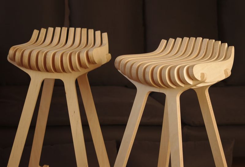 Image from
etsy.com
Image from
etsy.com
Design
Modeling: Blender - Seat parts
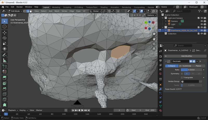
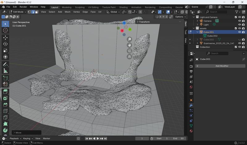
Actually, I had scanned a chair in advance for this assignment in week 5.
First, I thought about correcting the scan data to make it parametric.
However, I gave up on this as the data was too detailed and asymmetrical, making this
difficult.
Resource:https://styly.cc/ja/tips/blender-adjustment-scanmodel/
(Japanese)
Trying to connect paths…
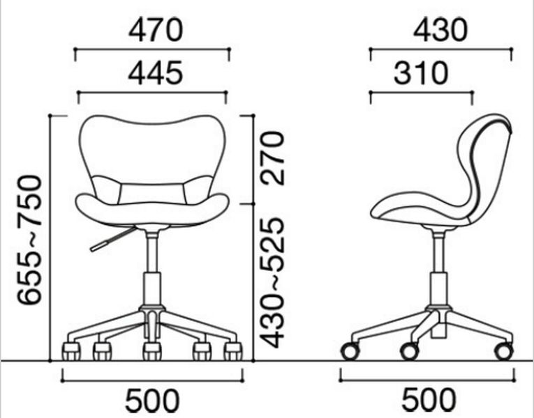
Instead, I decided to refer to the scan data and model it from scratch. The dimensions were listed on the page for (probably) the same product, so I decided to use those as a reference when creating it. *This is for personal use only!!
 Image
from : www.tanomail.com
Image
from : www.tanomail.com
Parametric furniture modeling was done with reference to:
https://www.youtube.com/watch?v=JH2FvcWZ_DE
https://www.youtube.com/watch?v=p6FwBzZGYXQ
https://www.youtube.com/watch?v=VcztiRzLlTA
However, when I tried to slice it following the steps in the video, it didn't work.
To solve this problem, I received the following feedback from Mr. Blender: Rico-san (Almost all the modeling advice I received in the following steps came from him):
- It seems that an add-on called LaserSlicer can be used for slicing
Try Laser Slicer addon
Laser Slicer Addon: https://blender-addons.org/laser-slicer-addon/
This is github page: https://github.com/rgsouthall/laser_slicer
I installed the add-on with following steps:
I couldn’t find the addon in the preference menu, so try download it from webpage.
Download zip file from add on page above. (DO NOT UNZIP IT!!!!! I made mistake with unzip
it…and could not add at first)
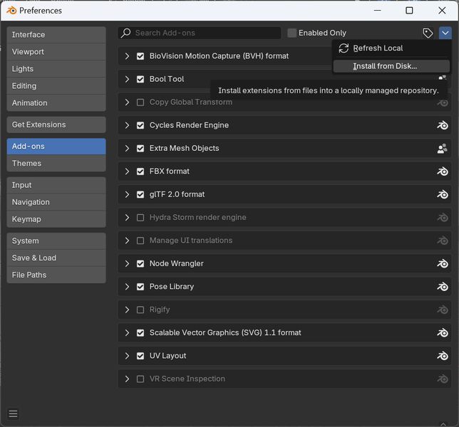
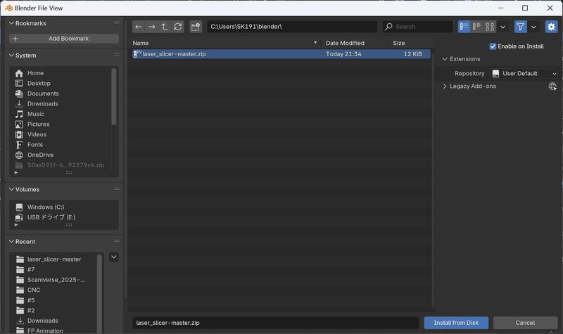
Now you can find the extension.
I also see the official tutorial video: BlendScript: Blender 2.8 - Laser Slicer
The slice is only xy dimension. So you have to rotate the object, to the dimension you want to cut
When I open the svg, the lines are not connected, so I tried to modify 3d modeling.
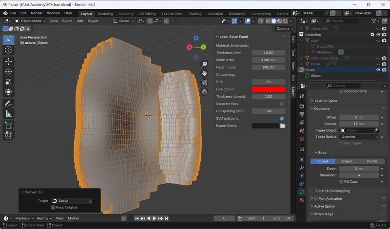
The slicing went well, but then I encountered a problem. First, when I looked at the sliced data, I saw that there was a strange gap between the seat and the back.
Second, in order to attach the chair legs, I need the exact thickness of the boards and the gaps between them, but even after searching, I couldn't find how to do this using this add-on.
Convert to Curve, and chose Data menu. Extrude 15mm. It seems too thick…
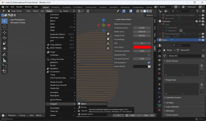
It seems I should create some kind of mesh after all. The advice I got here was:
- It's better to remodel from a simple shape.
- It's best to use the Boolean Tool.
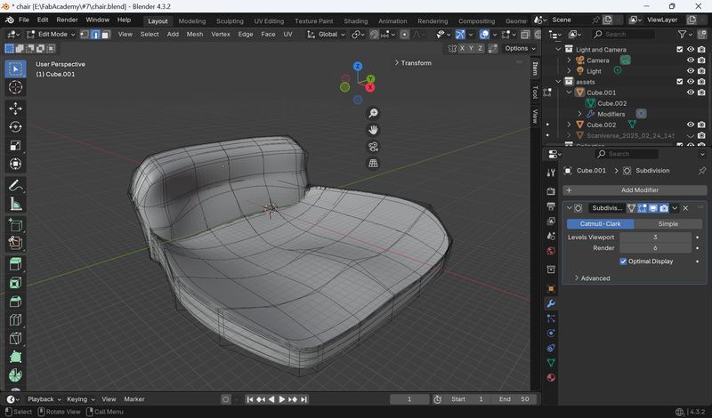
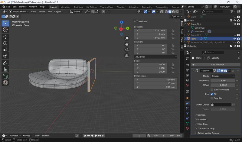
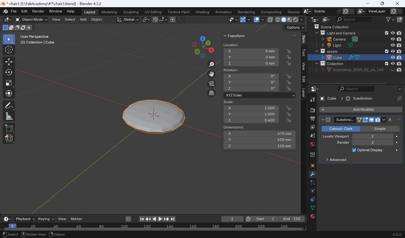
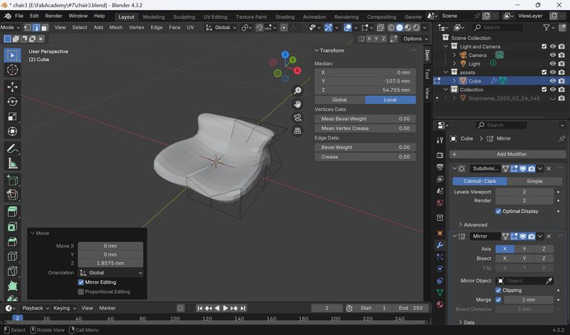
Remodel-1(Seat parts)
First, I remodeled it to be simpler.
Notes and points to note are as follows.
- Make sure you have same scale for Unit scale and Grid Scale.
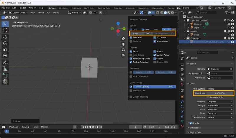
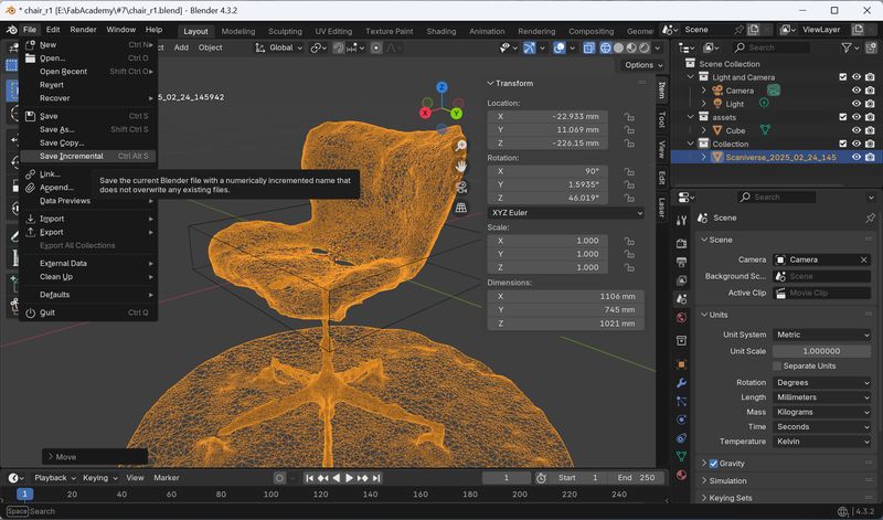
- It’s important to “Save Increment” to make versions.
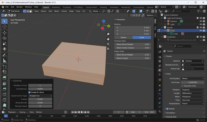
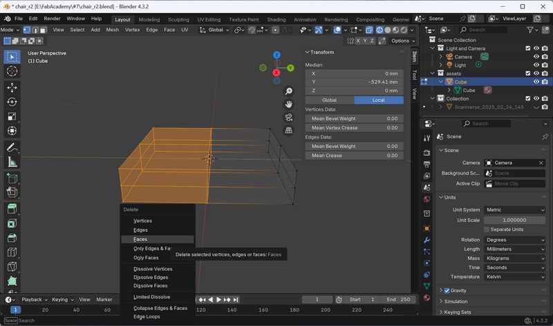
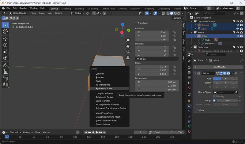
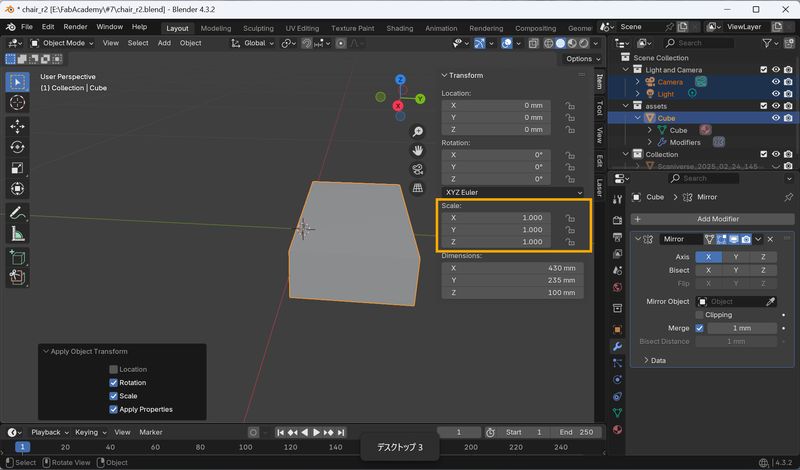
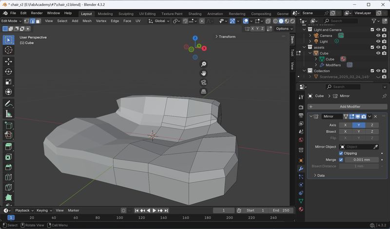
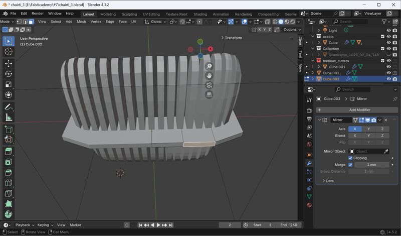
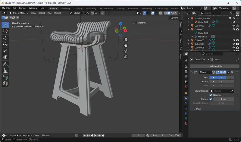
Use Mirror Modifier to make something symmetrical
Go Edit mode, subdivide 1 > Select half, and delete Faces > Apply Rotation &
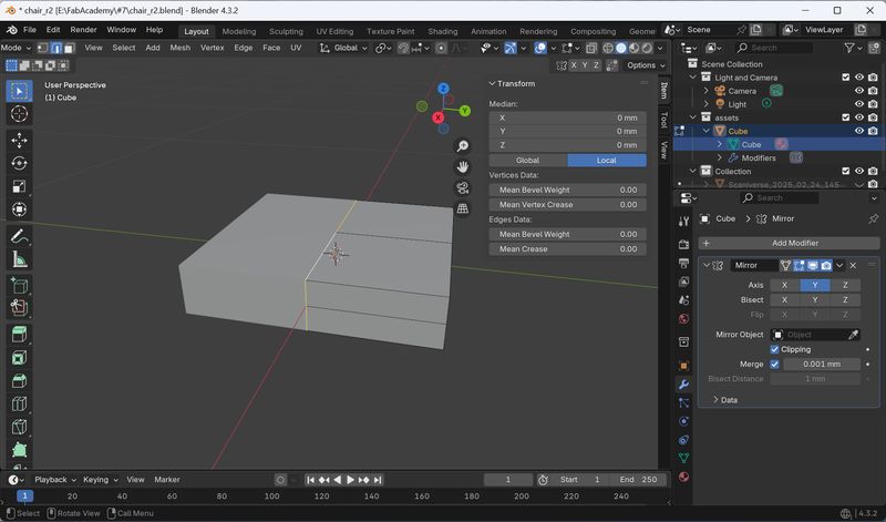
Scale > Then, add Mirror Modifier. Check “Clipping.”
(If you don't clip it, it will
separate when you push it inwards. if you clip it, it will merge towards the center)
(Don't mistake the Axis...)
The shortcuts are as follows:
- Ctrl + R: loop cut
- E: Extrude (Edit mode)
- Ctrl + B to bevel
However, it still seems too detailed.
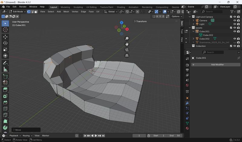
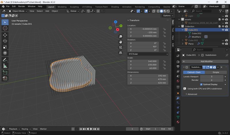
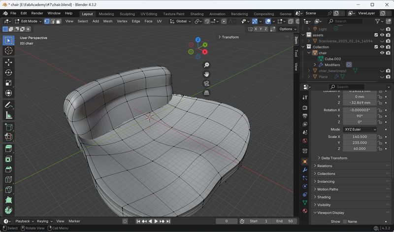
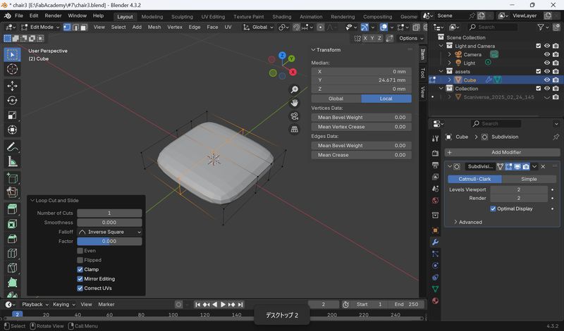
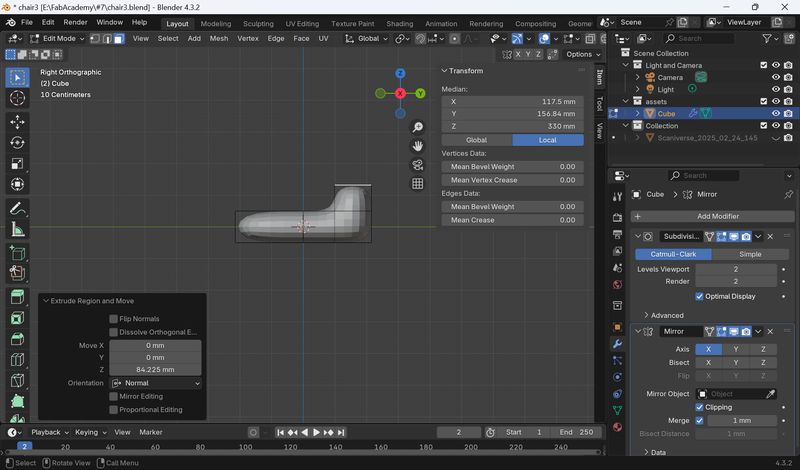
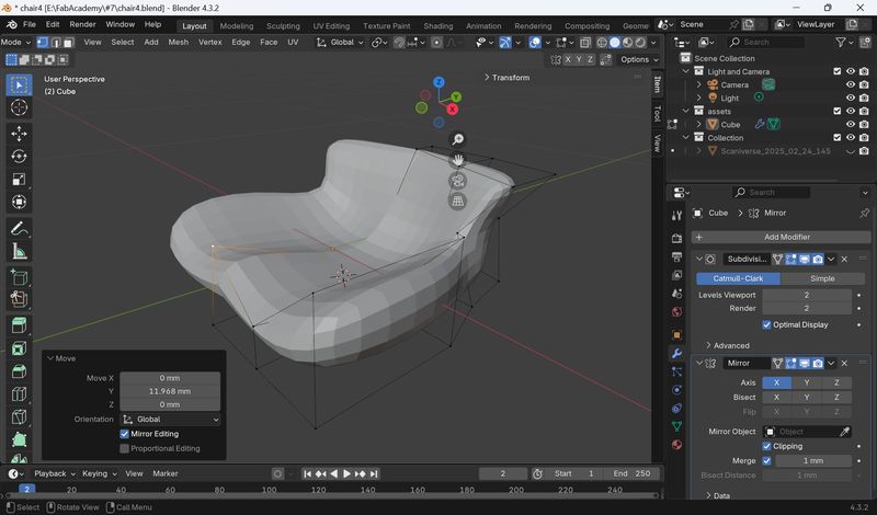
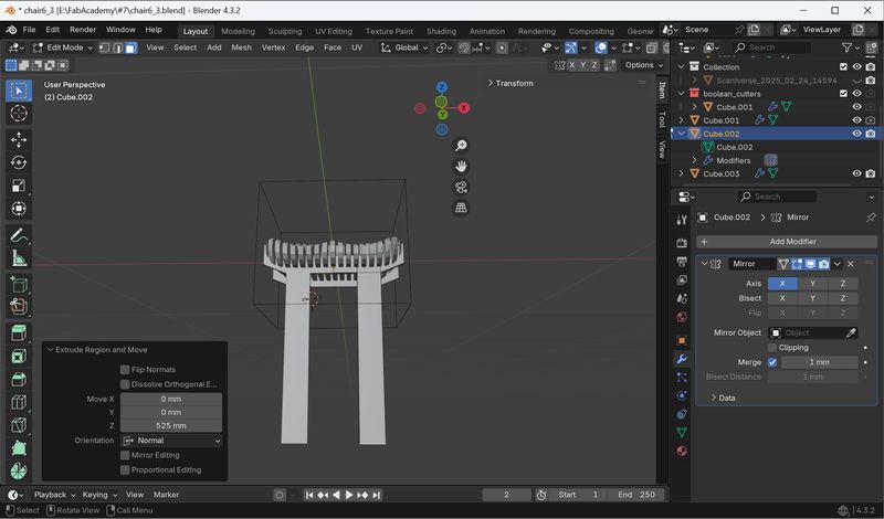
Remodel-2(Seat parts)
I remodeled it even more simply. I was too focused on making it as similar to the original
as possible, and made it too detailed, but I discovered that it's possible to create a
complex shape from a surprisingly small number of blocks.
(Also, the fact that I'd already spent so much time on it was a good condition for me to
make it even simpler.)
The key points are as follows:
- Select face and extrude to make backrest
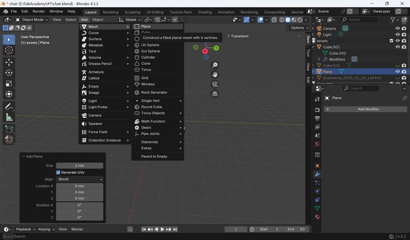
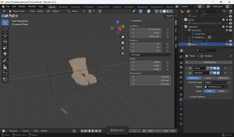
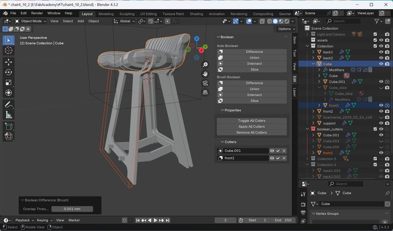
Boolean Tool
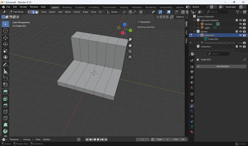
After that, I was taught how to use the Boolean tool and how to attach legs. First, I created a simple shape and tested it to see if it would work.
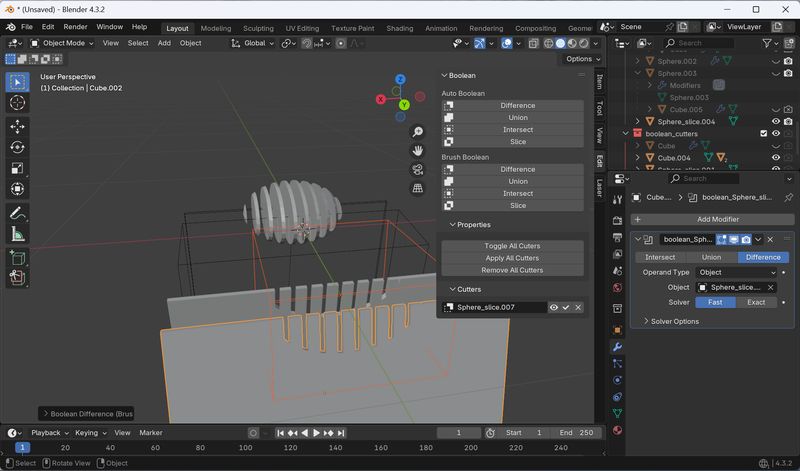
It seemed possible, so I tried it on an actual model. The steps are as follows:
Add
mesh> cube(Ctrl+A, type cu) > set z,y =1000(or same as material z y),
x=150(thickness) > Apply scale
Add Array modifier
Choose(Check) Constant offset, open the menu, and set distance. Then, set count.
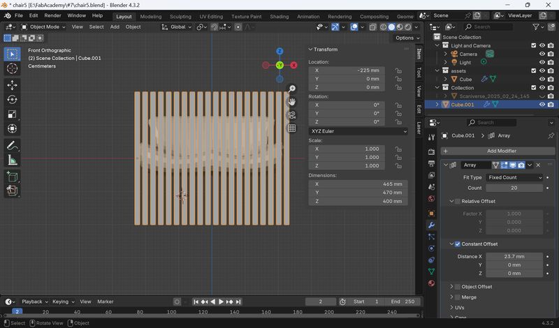
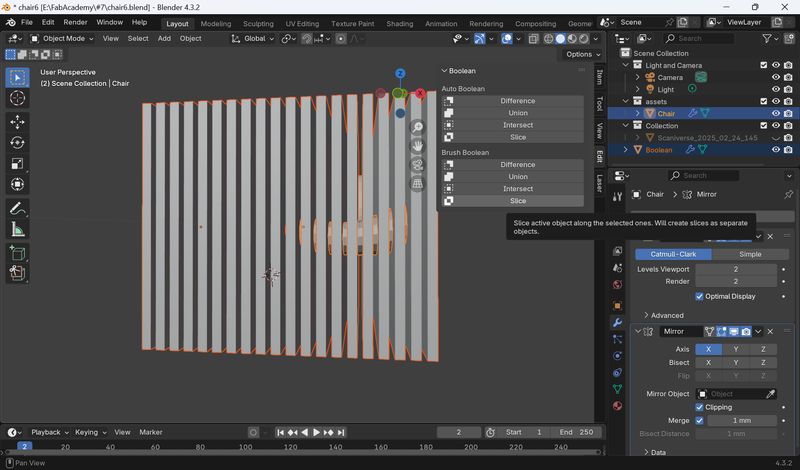
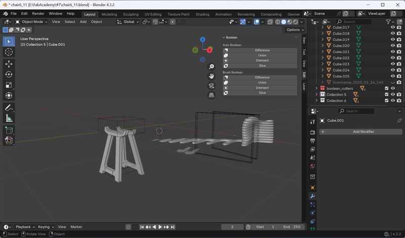
Open Boolean menu
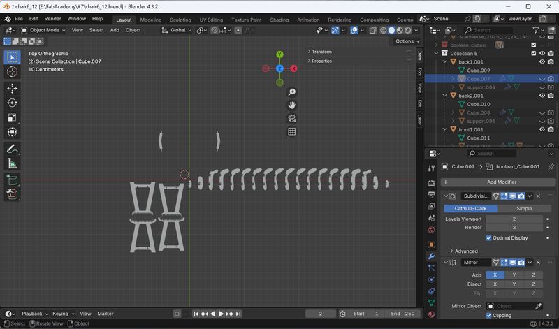
Choose Cutting tool(cubes)+Press Shift+Object(chair shape) > choose Slice > Apply
Boolean. (If not, it seems disappeared)
Compared count and distance:
count: 20, distance x: 23.7mm / count: 19, distance x: 25mm
I chose count: 19.
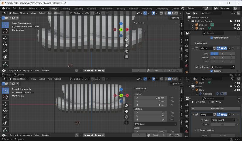
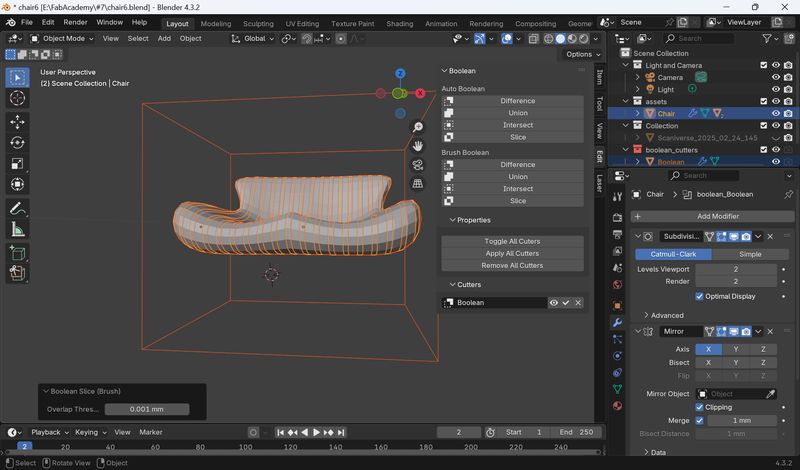
I was able to slice it successfully.
Notes:
- You need to attach the legs before you cut it into pieces.
Modeling - Leg part
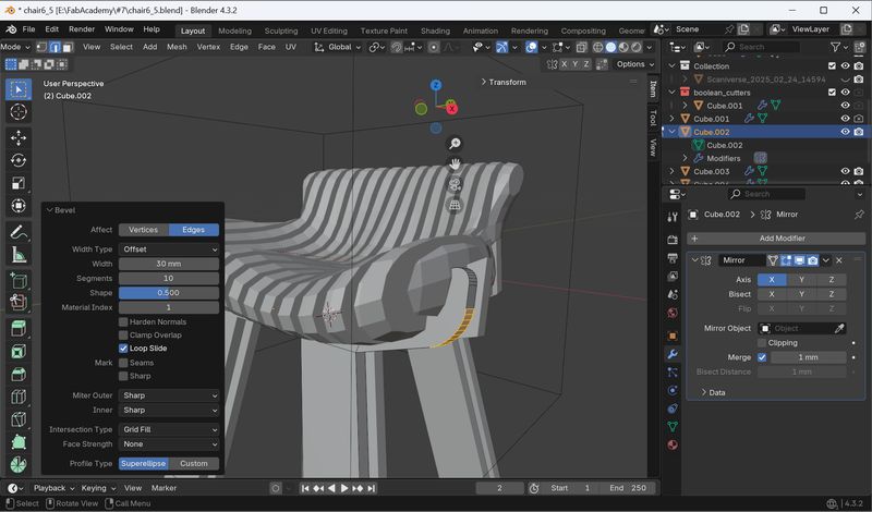
I was also taught to create the legs by starting with a simple shape.
Grab Face and Extrude
I used the bevel tool to round the corners.
Add Bevel: Go edit mode > Press Ctrl+B.
After looking at the actual board, I found that one board would not be strong enough, so I decided to put two on the front and two on the back.
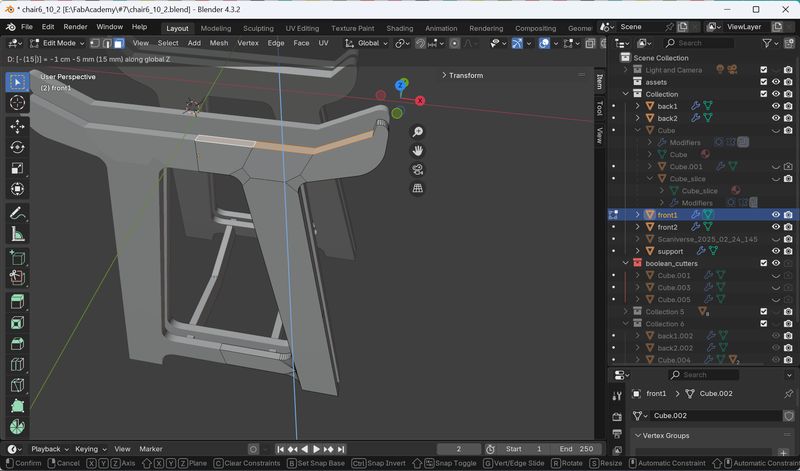
Modeling - support part
I tried to make a support part to connect the legs.
However, I ran into a problem here. If we placed two pieces, one in the front and one in
the back, at an angle, it would be impossible to fit the support parts from the top, as in
the original stool design.
I thought about what kind of design would be best. I considered straightening the legs,
but were concerned about balance. I considered ways to keep the diagonal design. Perhaps
it would be better if they could point at right angles. (There is an angular problem,
though.)
I ended up with the following design.
The final 3D model look like this:
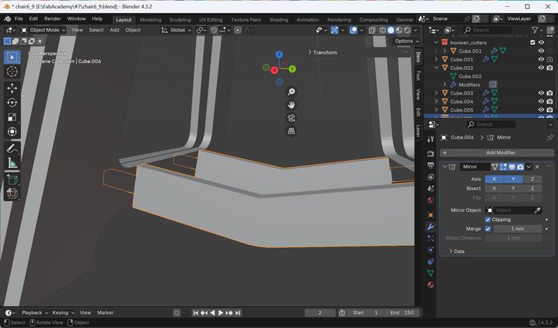
Make the cutout
- To create a cutout, you need to make a copy of the part.
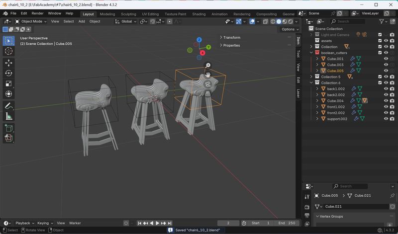
- If I made the cutout with each part as it is, the cutout would be too deep. Therefore,
I shifted each part by 15 mm.
(Copy 1: The foot was lowered 15 mm for the cutout of the chair part. Copy 2: The chair
was raised 15 mm to accommodate the cutout in the foot section.)
- Use “Difference” in Boolean menu to create the cutouts.
Make Planar
I found several examples of furniture modeling in Blender, but not many examples of actual
assembly. Therefore, how to export it was a big problem.
I found the following example and
decided to arrange it horizontally first.
"i
use blender to design and make furniture using a cnc machine . no"
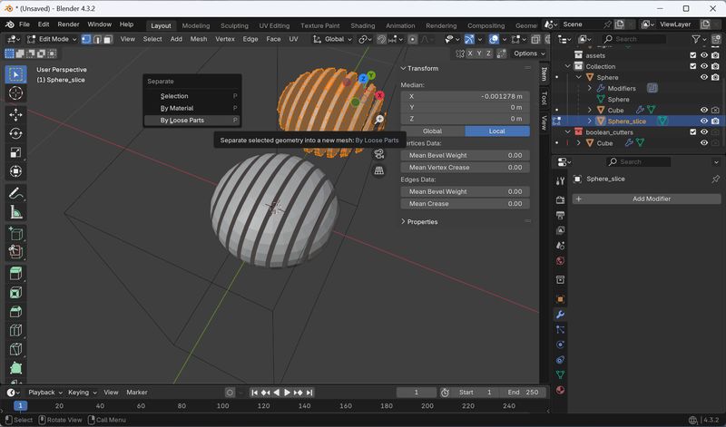
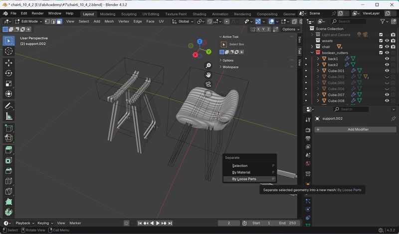
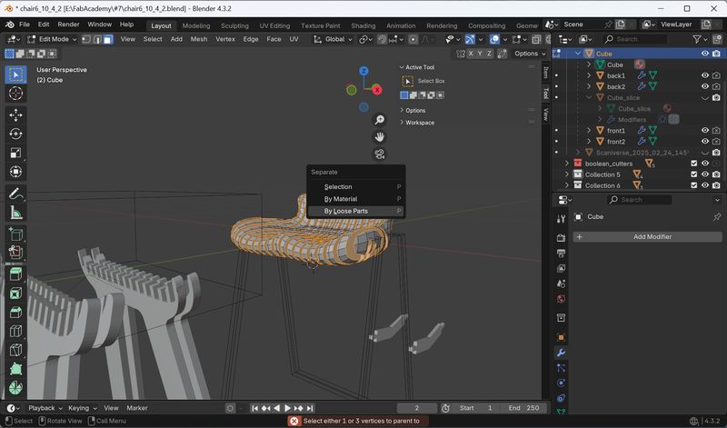
However, when I try to separate the model, the Boolean is released. I also
noticed that the seat part can't be separated.
The key points here (advice and tools I learned) are as follows:
- Apply all modifiers first.
- When separating the seat part, make sure to select the seat itself. (I accidentally selected the Slice layer.)
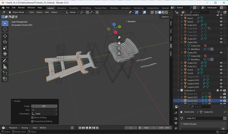
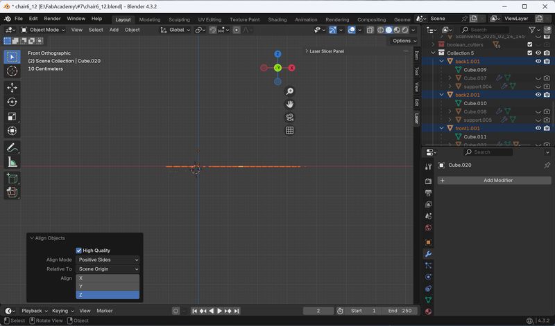
- Separate the seat part: Apply Mirror > Edit mode > Press P > Select By Loose Parts
- Align is in the Transform of the Object
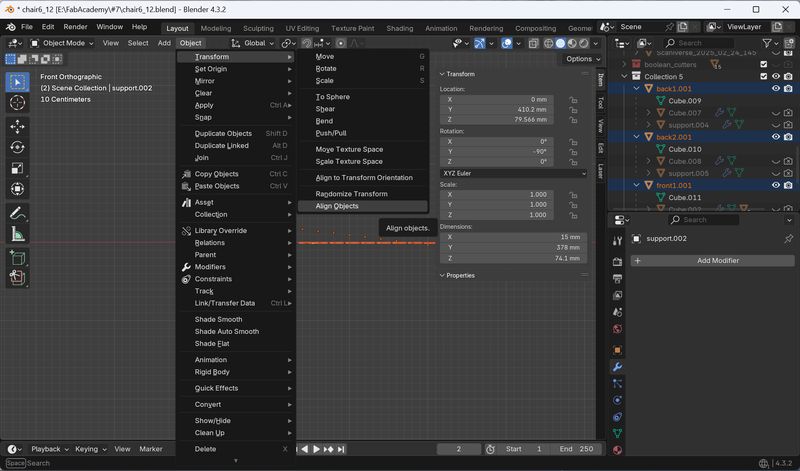
All the tools are now flat.
Convert to SVG - Freestyle SVG
There were several options and I was confused about how to do it. I followed Rico-san's
recommendation and used the "Freestyle SVG" add-on.
With this add-on, you
specify the outline you want, set the camera direction, and it will
vectorize the outline seen from the camera direction.
You can find this add-on in the blender menu with following steps:
Edit menu > Preference > search the extension in the “Get Extensions” menu and install it.
Reference: https://www.youtube.com/watch?v=9BMXlOV2ugE
1.Camera settings
It took me a while to figure out how to set the camera because I had never done it
seriously before. I set xy to 0 and set the camera angle straight down.
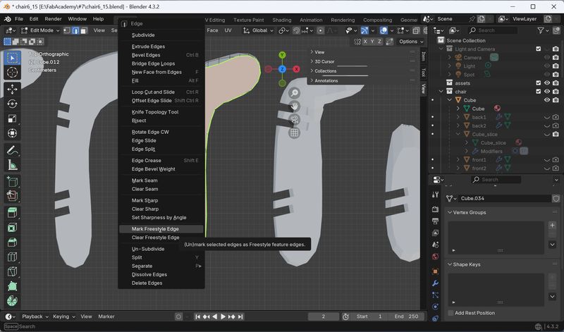
2.Extracting the outline
I also extracted the outline manually, so it was a very detailed job that took a lot of
time. (Especially the beveled part)
Here are some points I noticed:
- It is faster to select the outline by selecting the necessary face with the face tool
and then switching to the edge tool
3.Export settings
In the Render menu, select Freestyle SVG.
Then, “Render Image” from Render menu.
I exported it, but there are some objects that
are not visible on the screen...
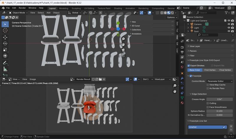
How can we not select these?
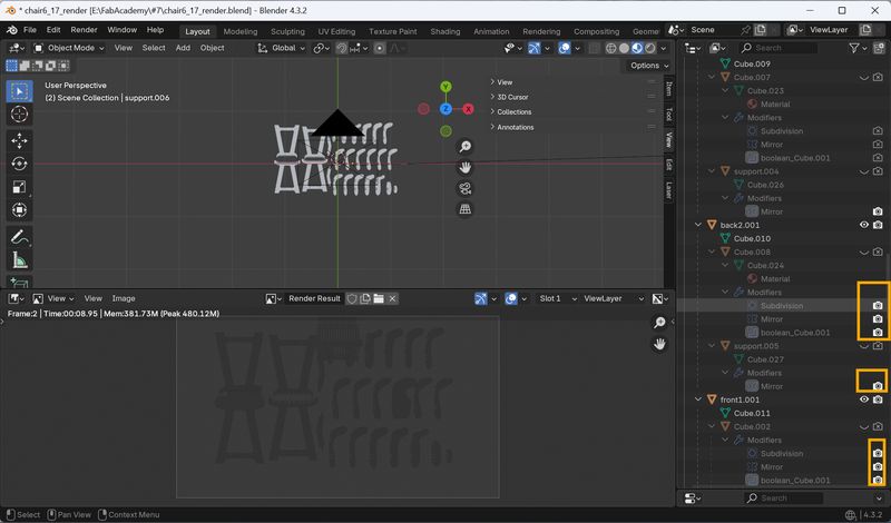
The lesson here is the following:
- Expand all layers and turn off all layers that have the camera icon turned on even though they are not visible.
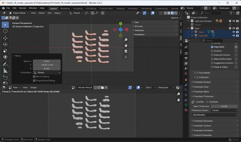
- I exported the seat and leg separately. This is because I wanted to reduce distortion caused by the camera angle.
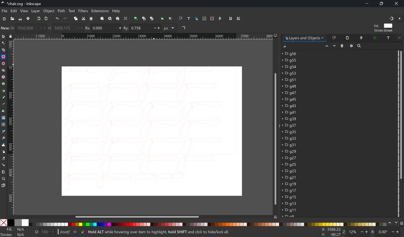
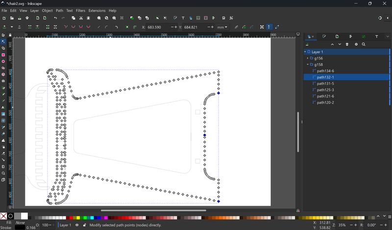
Modify 2D data - Inkscape
When I opened the exported svg file, I found a number of problems. The key points here are as follows:
- The size was inaccurate
→ I adjusted it so that the interlocking parts were the same size as the file output with the Laser Slicer addon. - The path wasn't closed
→ Paths were not closed here and there, they overlapped but were not connected, and there were extra parts, so it took a loooooooooooooooot of time to fix this.
The procedure is very painstaking: visually find unconnected paths, select them, and connect them with the ”join selected nodes” or “join selected endnodes” tools. (This process is probably quicker in Illustrator, as it will automatically detect paths.)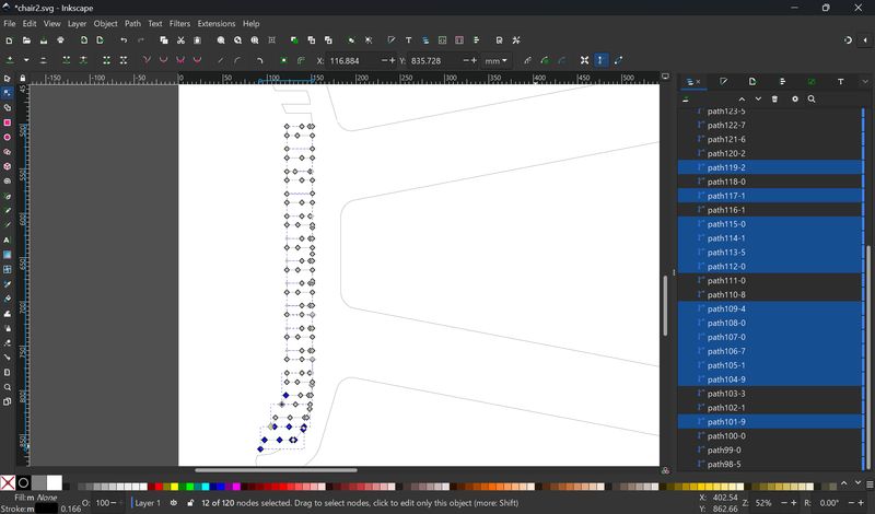
Once I've done this, finally ready to start milling.
Mill
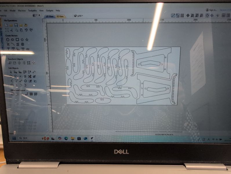
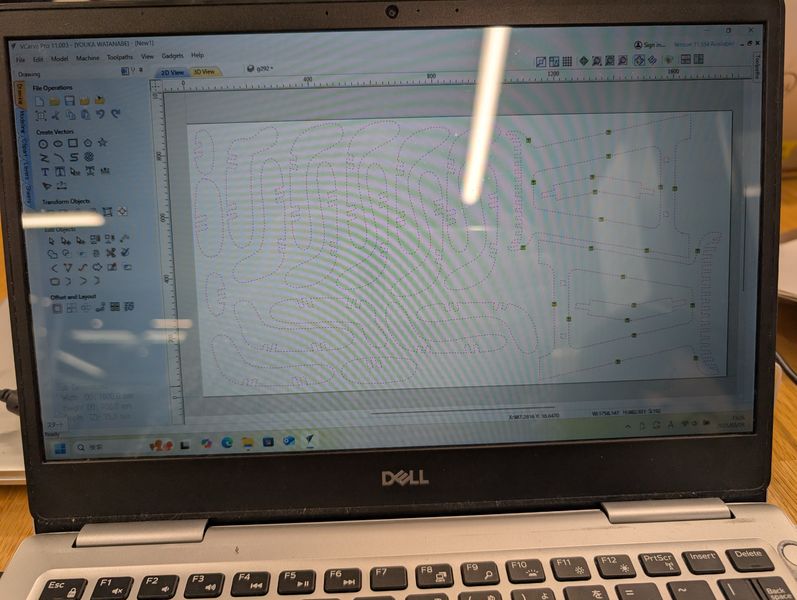
CAM: VCarve
VCarve is used in the following steps. (I used the FabLab PC to use the tool settings.)
- Job setup: Set job size, and x,y,z = 0.
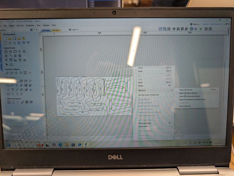
- Correcting paths: Use the join tool to correct any disconnected parts.
- Adding fillets: If you cut with the data at right angles, you will not be able to join the wood properly. (Because of the characteristics of the mill's shape, the cut ends will be rounded, so you cannot cut at right angles.) Therefore, you need to add fillets.
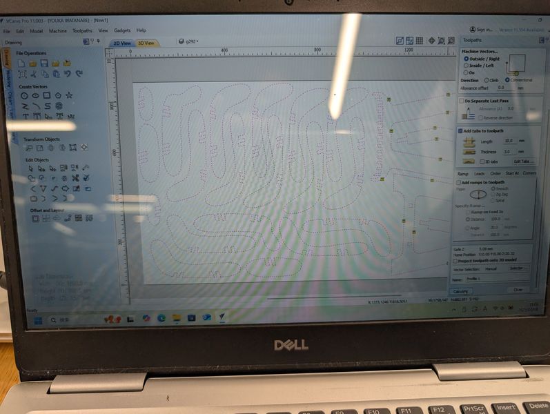
- Adding tabs: If you completely separate the parts, they will not be fixed and will move, which is very dangerous, so add tabs around the parts to connect them to the wood. Add them from the tab settings.
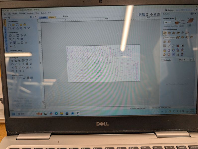
- Setting toolpath: Since I use it only for cutting this time, select the 2D Profile toolpath and set CuttingDepth, Tool, Machine Vector, and Tab.
- Save toolpath as sbp data (for shopbot) (do not choose unnecessary toolpath)
Job setup / Job material
| Parameter | Setting |
|---|---|
| Job type | Single sided |
| Job size | 1,800 (Width/X) x 900 (Height/Y) x 15 (Y) |
| Zero Position | Material Surface |
| Use offset | No |
| XY Datum Position | Left Bottom |
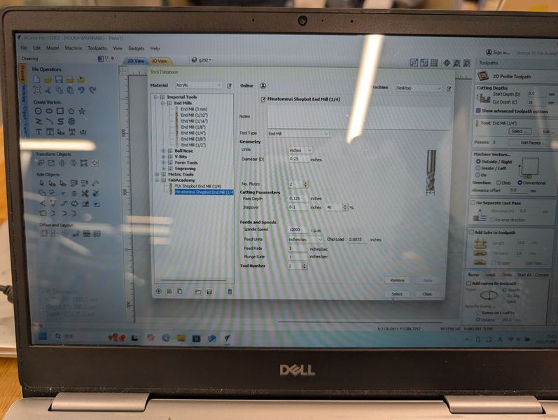
Endmill settings
| Parameter | 1/4” Downcut EndMill for Softwood |
|---|---|
| Cut | 1/2 x D (.125inches) |
| Chip Load per leading edge (inches) | 0.0075 |
| Flutes | 2 |
| Feed Rate (inches/sec) | 3 |
| Spindle speed, RPM | 12,000 |
Toolpath settings
| Parameter | Setting |
|---|---|
| Cutting Depths, mm | Start Depth: 0, Cut Depth: 16 |
| Tool | 1/4 Inch Downcut Endmill |
| Machine Vectors | Outside |
| Tab | Add Tab (Length: 11mm, Thickness: 3mm) |
The most time-consuming part was correcting the paths and adding fillets. Here is what I learned.
- Using the joint tool allows you to connect paths quickly. (At first, I used the path
tool, which took even longer.)
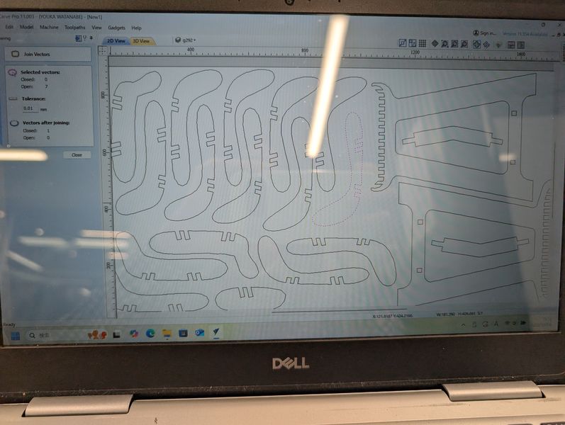
- By using Select All Open Vectors, you can see which parts have errors, but it seems
you need to find out which part of the part is the problem yourself. (This also took
time.)
- Add fillets with the Fillet tool. Select Dog bone Fillet.
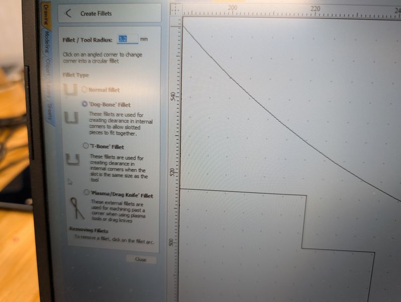
- The Fillet tool cannot automatically add fillets unless there is enough room for each cut. (This time, I drew the circle myself with the circle tool.This also took time.)
Once the data is prepared, you can finally start milling.
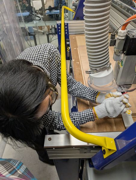
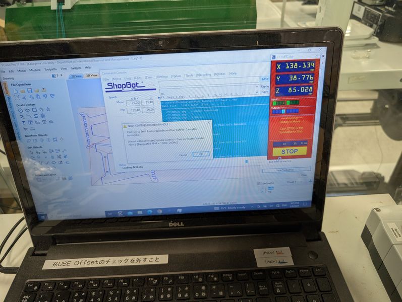
Machine Settings: Shopbot
The procedure for using Shopbot is as described on the group page.
- Turn on the power
- Test run
- Fix the material
- Attach the tool
- Set the origin in the xy direction (c3 command)
- Set the origin in the z direction (check that the power is on, then use the c2 command)
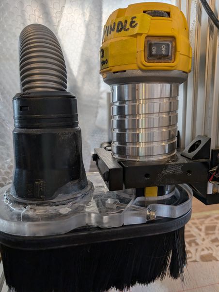
- Attach the dust collector cover
- Load the file (FP command)
- Set No offset
- Press the start button on the screen
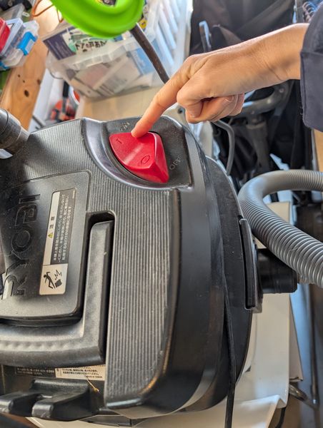
- Turn on the dust collector (important!)
- Use the key to physically turn on the spindle interlock
- Click OK to start milling.
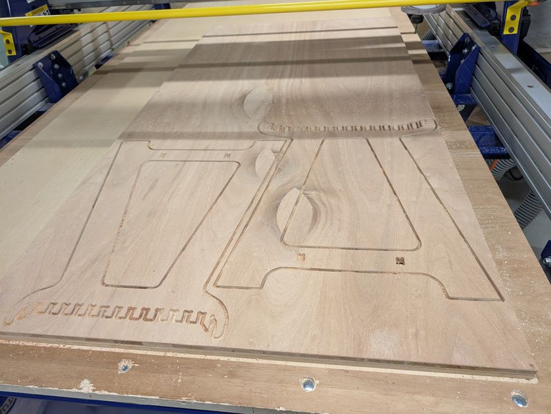
I could cut well without any problems!!
When I've done, turned off the spindle interlock and the dust collector, and cleaned up.
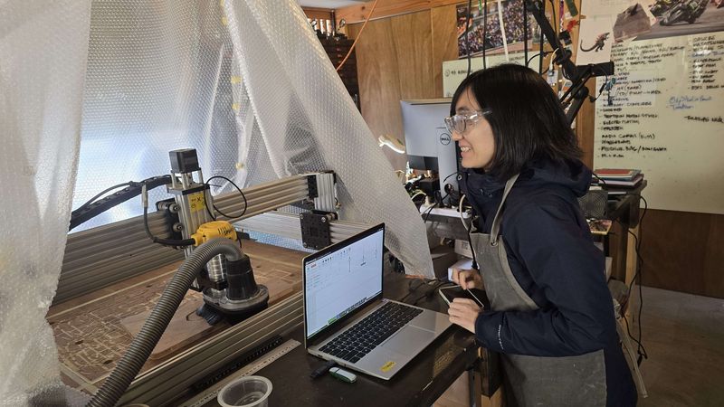
Unfortunately, I could not able to finish everything in two days. Since the available time at FabLab Minatomirai was limited, I continued the work at SkyLab.
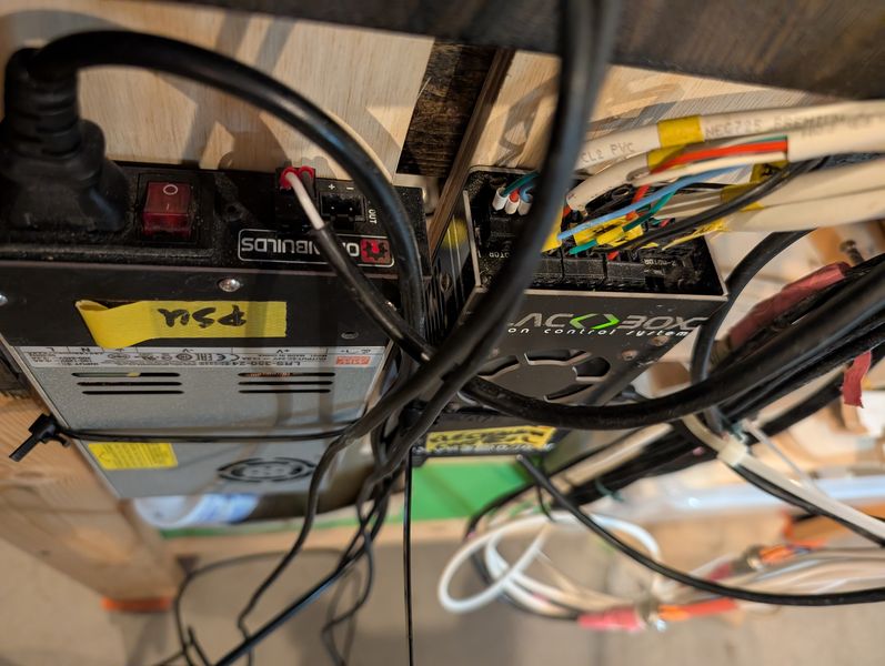
Adjust to fit the machine
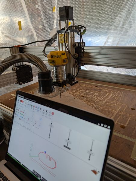
The machine in SkyLab is Openbuilds
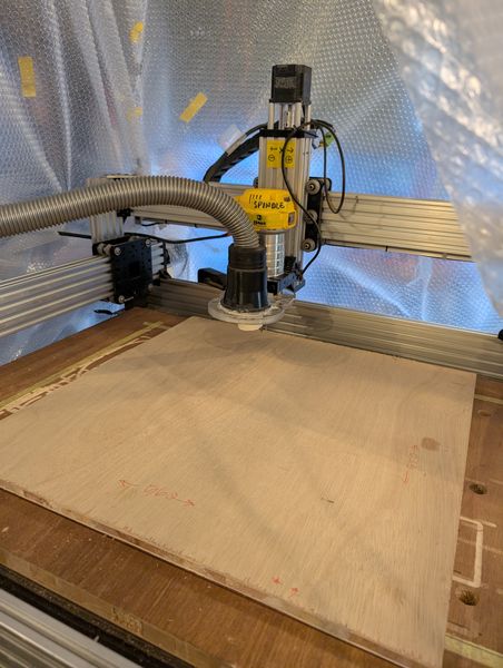
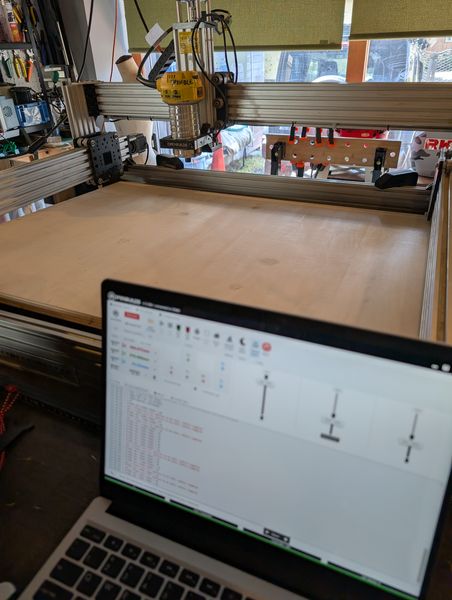
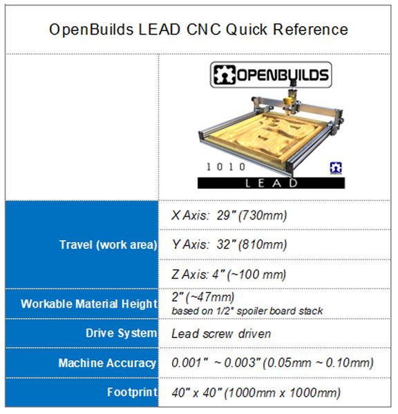 OpenBuilds LEAD CNC
Because the machine is different, I did a test cut. (The procedure for the test cut is
described below.)
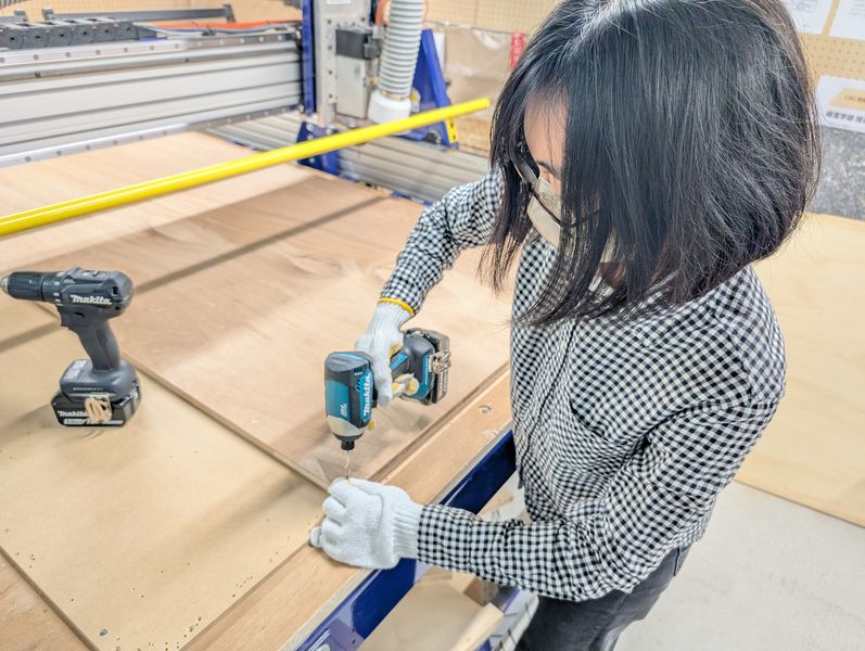
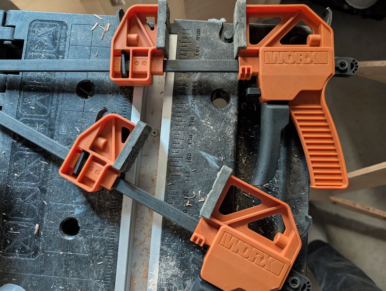
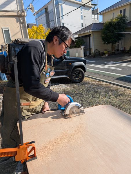
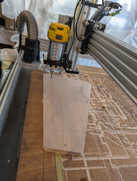
Also, since the machine is not as large as Shopbot, I first cut the wood into small pieces
(Riko-san helped me). I learned how to use clamps as well. Before cutting the wood, I
calculated the size so that all the pieces would fit together nicely.
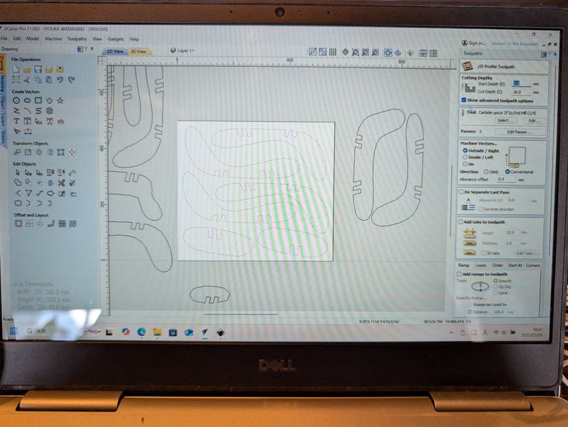
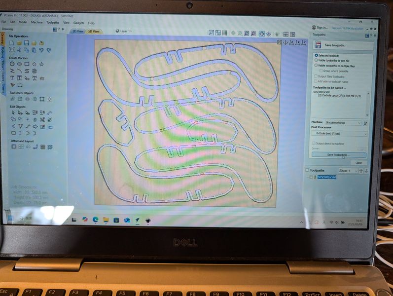
VCarve Setting
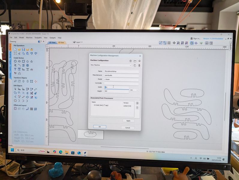
You need to change the VCarve settings to suit the machine.
- Machine Configuration
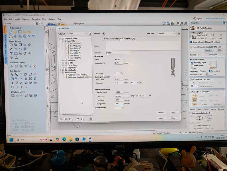
- Change tool settings
- Edit and output the toolpath data to suit the size of the material.
Job setup / Job material
| Parameter | Setting |
|---|---|
| Job type | Single sided |
| Job size | I split original data into four files: 500 (Width/X) x 350 (Height/Y) x 15 (Y) 500 (Width/X) x 560 (Height/Y) x 15 (Y) 505 (Width/X) x 350 (Height/Y) x 15 (Y) 505 (Width/X) x 560 (Height/Y) x 15 (Y) |
| Zero Position | Material Surface |
| Use offset | No |
| XY Datum Position | Left Bottom |
Endmill settings
| Parameter | Carbide upcut 2 flutes Sq End Mill (1/4) |
|---|---|
| Cut | 1 x D |
| Chip Load per leading edge (mm) | .0312 |
| Flutes | 2 |
| Feed Rate (mm/sec) | 1,000 |
| Spindle speed, RPM | 16,000 |
Toolpath settings
| Parameter | Setting |
|---|---|
| Cutting Depths, mm | Start Depth: 0, Cut Depth: 16 |
| Tool | Carbide upcut 2 flutes Sq End Mill (1/4) |
| Machine Vectors | Outside |
| Tab | Add Tab (Length: 10mm, Thickness: 3mm) |
Setting for test cut
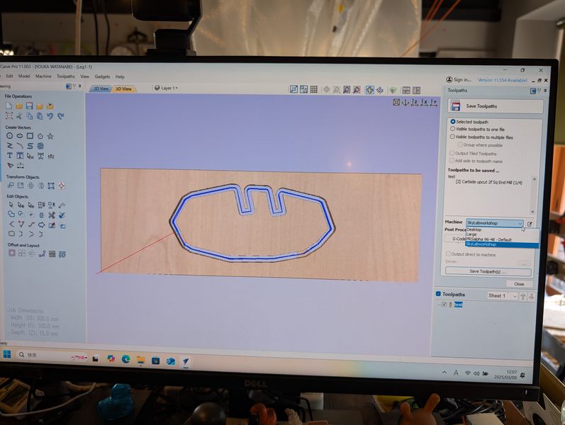
Settings for final output

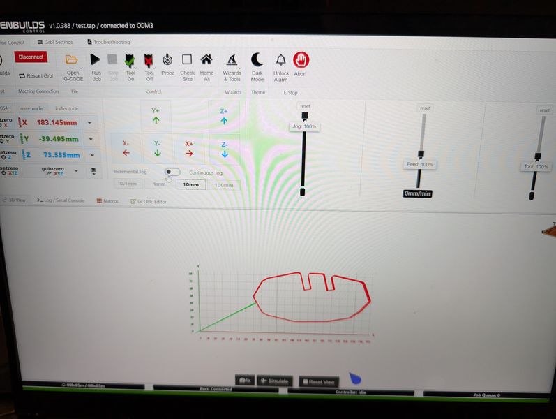
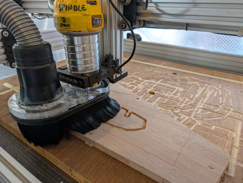
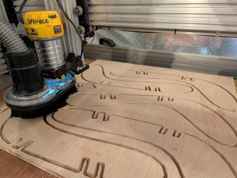
Machine Settings: Openbuilds
The steps for using it are basically the same, but it's simpler, so it's easier to understand how it works.
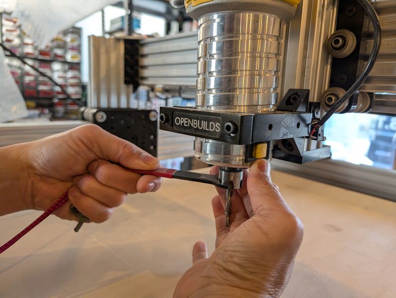
- Turn machine on
- Put Material
- Put tool
- Set machine home(x, y)
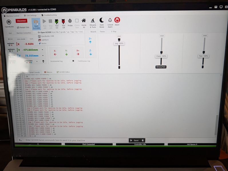
- Open G-Code
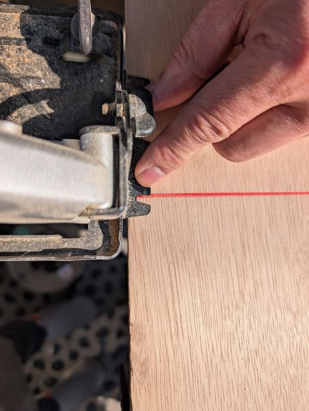
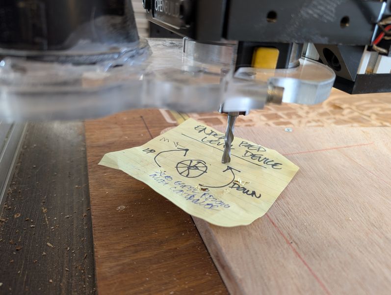
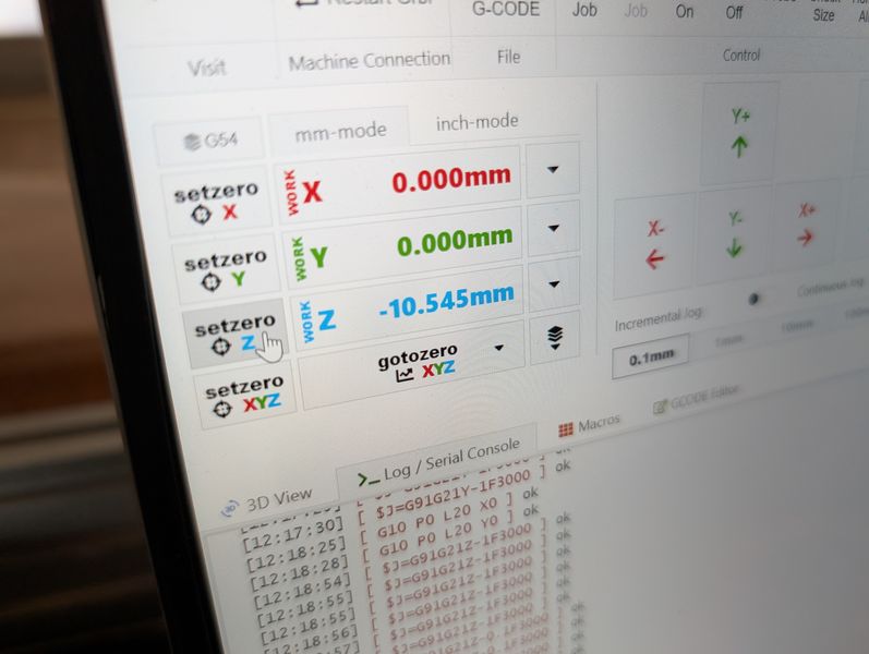
- Set work home(x, y):
- Set work home(z): use paper, and find where it stuck
- Check job size
- Fix plate with screw
- Put vacuum cover (put smaller nozzle)
- Turn vacuum on
- Turn spindle on manually
- Runjob
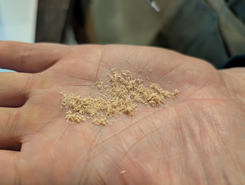
During job- pick dust and check if it works correctly
- Clean dust: if it too much
- Be careful with plugs, codes and nozzles
- Stop spindle
- Stop vacuum
- Check if it is ok remove
- Remove screws
- Vacuum & clean up
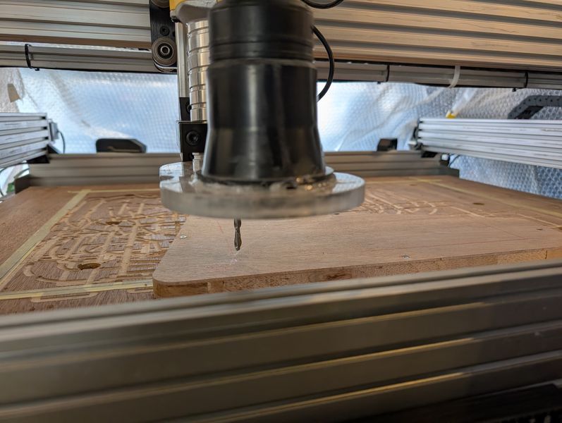
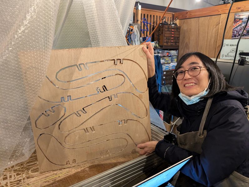
First, I did a test cut with the above steps. Then, I checked whether the test piece fit well with the part I cut with Shopbot.
It seemed to fit well, so I cut the remaining pieces using the same settings.
The problems I faced with Openbuilds and the solutions are as follows.
- If x, y, z are too close to the edge and hit a corner, it will crash.
→ Home all (always Home all before setting)
If you keep the material in the center, it will not crash (instead, set work home to the edge of the material) - An error occurs when you run a job
→ You can make it move by correcting the GCode. - Some parts are not cut enough
→ Set z lower than 0.
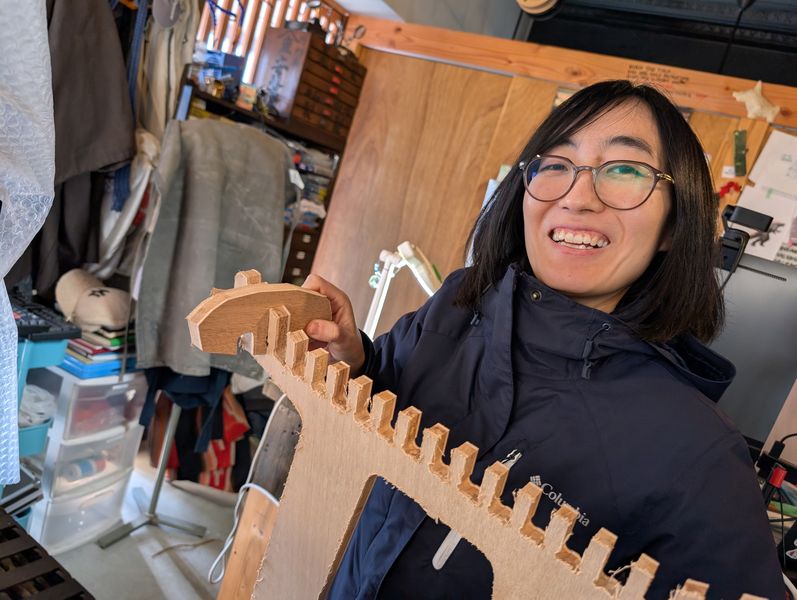
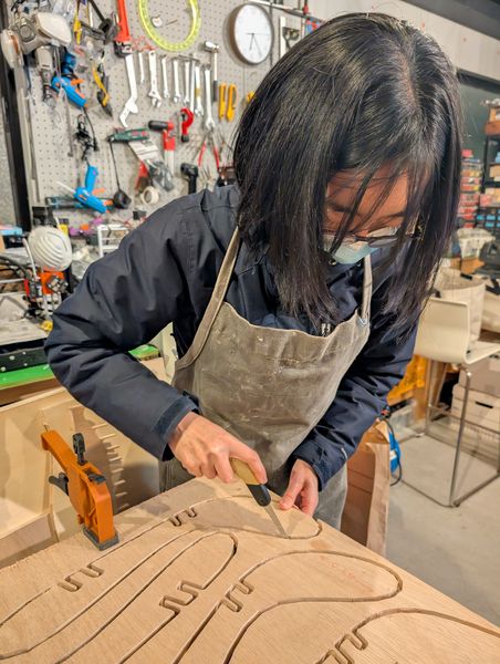
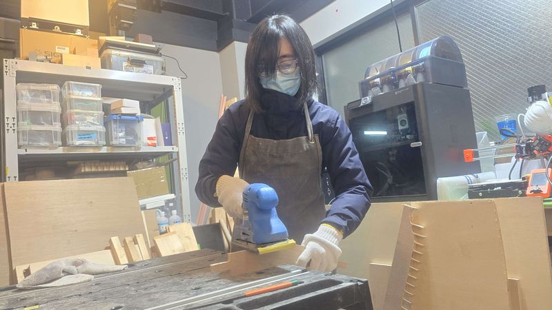
Assemble
Before assemble them, I sanded it down.
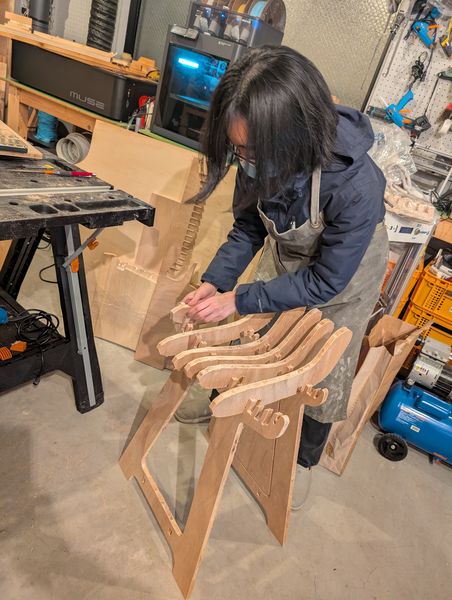
The seat parts and legs fit together nicely.
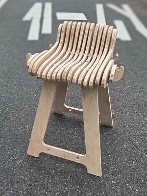
Here is the final result after assembly:
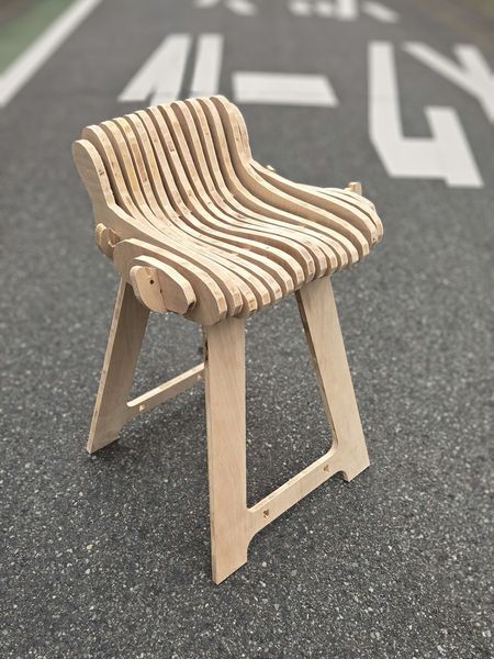
Here are some points to improve:
- The support parts that connect the legs don't fit together well
- I didn't notice this before printing, but there are unnecessary cuts on both ends for legs
- In order to sit on it, I need to cut all the parts and complete the assembly
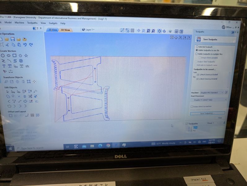
Outcome
Data for Machining
Leg1-1: leg for shopbot data
no x no: seat parts for openbuild data
After I started making it, I realized that making furniture with Blender is not very common. There seems to be room for further research and improvement in how to prepare the data for use in CAM software. (I've learned that it is best to use Rhino in this case in Asia Review from Saheen. I'd like to try it next time.)
I also need to get more used to modeling practical objects.
But otherwise, I'm quite happy with the results. It was a great learning experience, especially trying out two different Machines!
I had more stumbles this week than usual. I learned that it takes time to make something exactly how I want it, especially when doing it in an unconventional way. It was hard, but it was a very fun week for me, as I was able to make a large, practical object for the first time!
(In this page I used DeePL and Google translate for some sentences)
Resources
https://styly.cc/ja/tips/blender-adjustment-scanmodel/
(Japanese)
https://www.youtube.com/watch?v=JH2FvcWZ_DE
https://www.youtube.com/watch?v=p6FwBzZGYXQ
https://www.youtube.com/watch?v=VcztiRzLlTA
https://www.youtube.com/watch?v=9BMXlOV2ugE