#6 Electronics Design
This week I learned how to use EDA tool, and test equipment to develop boards.
Assignment
Group assignment
Individual assignment
Outcomes
What did I do this week: 1. Group Assignment
The group assignment page - week06
Use the test equipment in your lab to observe the operation of a microcontroller circuit board (as a minimum, you should demonstrate the use of a multimeter and oscilloscope)
This week, we tried Multimeter and Oscilloscope.
With Multimeter, we can measure continuity, voltage, resistance.
With Oscilloscope, we can measure voltage changes (current waveform).
Note for me:
AC: Alternating current. This is the electricity that flows through an average household. We
don't use this in the FabLab unless we're using large machines such as big motors.
DC: Direct current. This is basically what we use for electronics.
About Multimeter:
It has red and black wires, and we use the dial to select what we want to measure.
Be careful with batteries, LEDs, and other devices that have polarity.
Black: negative
Red: positive
*Notes on units:
1. Voltage: mV/V
2. Resistance: Ω/kΩ
3. Continuity: -
4. Current: μA/mA/A
For details, please see the group page: The group assignment page - week06
What did I do this week: 2. Individual assignment
Use an EDA tool to design a development board that uses parts from the inventory to interact and communicate with an embedded microcontroller
Procedure
In class, we learned about the steps of EDA (Electronic Design Automation) as follows:
sketch, schematic entry, component (auto)placement, (auto)routing, simulation,
fabrication
In addition, during the local session, we learned in more detail how to use the EDA tool
KiCAD.
During that time, we learned the following steps (below list by Rico-san):
- List desired Functionality for the board…how many connected devices?
- Select Components…MCU + Header Pins + Passive & Active Electronic devices
- Test component connections and electrical functionality > breadboarding
- Make a Schematic diagram connecting all your electronic components
- Specify Design Rules (based on PCB milling process)
- Make a Board Layout that is sensible, practical and millable
In other words, first, I need to think about the necessary functions and components.
So, I decided to organize the functions I would need for my final assignment first.
Before design: Research for board design
(In this section, I document some configuration considerations, but you can also jump directly to the KiCad working section.)
The instructors gave me a lot of advice, but if multiple functions are required,
multiple microcontrollers must be used for each function.
So I used ChatGPT to investigate which microcontrollers to use.
Below is an excerpt from the conversation with ChatGPT (I searched in Japanese and
below are translated).
Question:
If I were to create the following program, what number and type of microcontrollers
would meet the requirements?
・By tapping the sphere, the projection image is projected, music is played, and the LED
light is turned on at the same time.
・The data to be projected can also be edited on a smartphone.
Answer (excerpt from summary):
With the following configuration, each role can be assigned and a system that
efficiently meets the requirements can be built.
| Application | Microcontroller | Reason |
|---|---|---|
| Touch input detection | ESP32 | Supports Wi-Fi and Bluetooth and has touch sensor function, allowing communication with smartphones. |
| Projection | Raspberry Pi 4 | High-performance processing power and HDMI output, ideal for receiving and projecting video data. |
| Music playback | ESP32 | Supports Bluetooth audio, low power consumption, ideal for music playback. |
| LED light control | Arduino Uno/Nano | Arduino Uno/Nano Suitable for simple I/O control and real-time LED control. |
I also asked about configuration suggestions when using Xiao, which I looked into last
time.
Question: Regarding the answers given above, please tell me the configuration when
using Xiao.
Answer (excerpt from summary):
| Application | Microcontroller | Reason | Connection method |
|---|---|---|---|
| Touch input detection | Seeed Studio Xiao ESP32 | Wi-Fi, Bluetooth support, touch sensor function | Connect the MPR121 sensor and detect touch. |
| Projection | Raspberry Pi 4 | High-performance processing power, HDMI output | Send video data from the Xiao ESP32 via Wi-Fi and project it with the Raspberry Pi 4. |
| Music playback | Seeed Studio Xiao ESP32 | Bluetooth audio support, low power consumption | Connect to your smartphone via Bluetooth and play music. |
| LED light control | Seeed Studio Xiao RP2040 | Simple I/O control, real-time LED control | Control an LED strip (e.g. WS2812). |
I also asked the following question because I wanted to get an idea of how the whole
system would be configured.
Question: Please tell me how to configure the touch sensor and microcontroller, and the
projector and microcontroller so that an image is projected onto a wall when the
surface of a glass sphere is tapped.
Answer (excerpt from summary):
Example of the overall system configuration
| Application | Microcontroller | Sensor | Projector | Connection method |
|---|---|---|---|---|
| Touch input detection | ESP32 | MPR121(touch sensor) | - | ESP32 receives touch input and detects touch position |
| Projection | Raspberry Pi 4 | - | HDMI projector | Receives data from ESP32 via Wi-Fi, and Raspberry Pi 4 projects the image |
| Touch signal processing and instruction output | ESP32 | MPR121 | - | Touch signal processing and command output ESP32 MPR121 - ESP32 receives touch signal and sends image to projector |
| Image projection | Raspberry Pi 4 | - | HDMI projector | Image projection Raspberry Pi 4 - HDMI projector Raspberry Pi 4 projects image (HDMI) |
However, as I researched, I found that both the projector and the Raspberry Pi 4 were
expensive, so I added the following question.
Question: Can you tell me a configuration that can be made a little more inexpensively
(about half the price, if possible)?
Answer (excerpt from the summary section):
Example of a cost-reduced configuration
| Application | Microcontroller | Sensor | Projector | Connection method |
|---|---|---|---|---|
| Touch input detection | Arduino Nano | TTP223(1-point touch sensor) | - | Receive touch input with Arduino Nano |
| Projection | Raspberry Pi 4 | - | Small portable LED projector | Project images to a projector via HDMI connection |
| Touch signal processing and instruction output | Arduino Nano | TTP223 | - | Receive touch signals with Arduino Nano and send them to the projector |
| LED Light Control | Arduino Nano or ATtiny85 | - | - | Control an LED strip (e.g. WS2812) |
Although the Raspberry Pi 4 is expensive, the Raspberry Pi was still recommended for
the projection part, so I asked the instructor.
I’ve advised that if it's not full HD, I can connect a pico and a board. For example,
there are the following options. This will not be too expensive.
PiCowbell
Raspberry Pi Pico
https://www.adafruit.com/product/4984
https://www.raspberrypi.com/products/raspberry-pi-zero-w/
The projection part seemed to require further consideration, so I decided to consider
it separately.
I researched not only the projection part, but also what options there are for sensors.
I found that there are so many options, and it seems difficult to narrow it down at
this point.
However, as I continued my research, I found that the MPR121 was recommended.
*Excerpts of recommended parts from ChatGPT:
- Want to distinguish fine touch areas → Capacitive touch (MPR121)
- Want to distinguish light taps → Pressure sensor (FSR)
- Want to detect taps by vibration → Piezo element
- Want to identify the area without contact → ToF or IR sensor
It would
be better to do a lot of touch input and output at once. So I thought I might want to
use the MPR121 (touch sensor).
*MPR121:
The sensor is available with a breakout board to make it easier to solder the small
sensor.
Adafruit 12-Key Capacitive Touch Sensor
Breakout - MPR121 - STEMMA QT
This chip can handle up to 12 individual touchpads
You can select one of 4 addresses with the ADDR pin, for a total of 48 capacitive touch
pads on one I2C 2-wire bus.
If so, would the ESP32 be the best microcontroller?
When it comes to creating a microcontroller, it's best to start by preparing the
essential microcontrollers.
We mentioned various conditions above, but the essential condition for the final
assignment is "projection when tapped."
At the very least, for the tapping portion, you'll need an ESP32 or Arduino Nano.
So, I took a quick look at the datasheets again to determine which one to use to create
a board.
I also looked into the ESP32S3, ESP32C6, and ATmega328P.
Options to consider at this point
| Board | ESP32 | Seeed Studio XIAO ESP32S3 | Seeed Studio Xiao ESP32C3 | Seeed Studio XIAO ESP32C6 | Arduino Nano | Raspberry Pi Zero W (Projection) |
|---|---|---|---|---|---|---|
| Microcomputer | ESP32 | ESP32S3 | ESP32C3 | ESP32C6 | ATmega328P | RP3A0 |
| Datasheet | esp32_datasheet_en.pdf | esp32-s3_datasheet.pdf | esp32-c3_datasheet_en.pdf | esp32-c6_datasheet_en.pdf | A000005-datasheet.pdf | https://www.raspberrypi.com/products/raspberry-pi-zero-w/ |
OMG I used whole day to think about this…I have to start using the tool anyway…
Final configuration plan at this point
After this, during the Lab session, I was advised that if touch + projection is required, the following configuration example would be good. As expected, a Raspberry Pi is required instead of a microcontroller to project videos.
| Application | Microcontroller | Input | Output |
|---|---|---|---|
| Touch input detection | xiao (RP2040 or ESP32) |
step response (need to decide numbers) |
- |
| Projection | Raspberry Pi | - | projector (need to be chosen) |
Try KiCAD
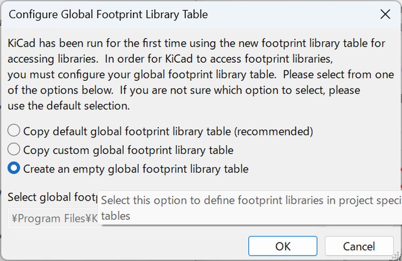
I decided to try KiCAD, which was recommended in local session.
First, in preparation, I did the following according to the Local Session materials:
Install KiCAD
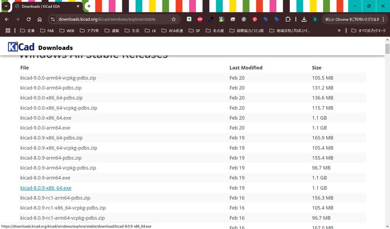
https://www.kicad.org/download/
Following Rico-san's advice, install the previous release from the following page.
https://downloads.kicad.org/kicad/windows/explore/stable
After install
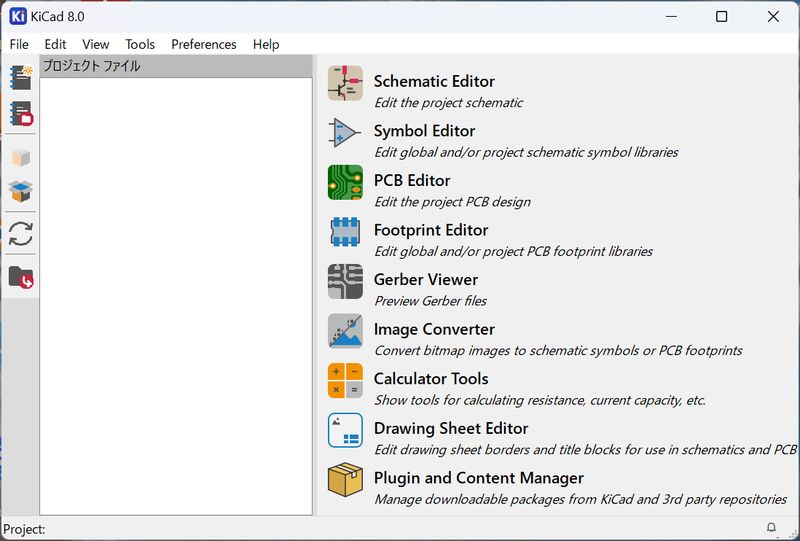
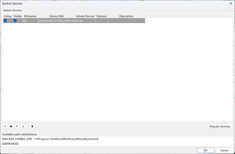
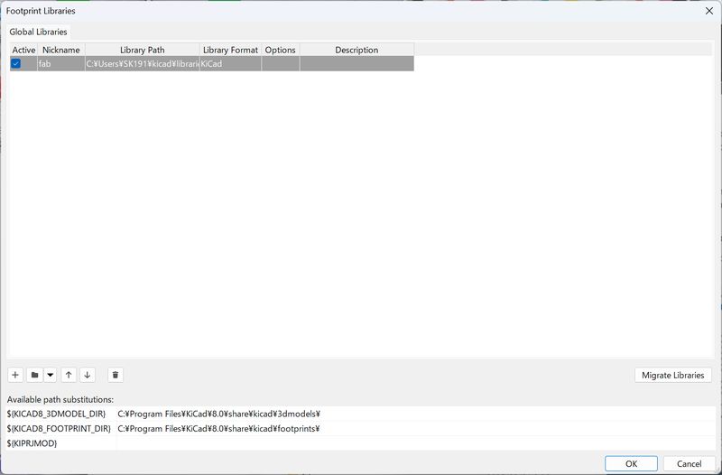
Add FabLibrary
https://gitlab.fabcloud.org/pub/libraries/electronics/kicad
Follow the instraction on the page. Download the library and add it on KiCAD.
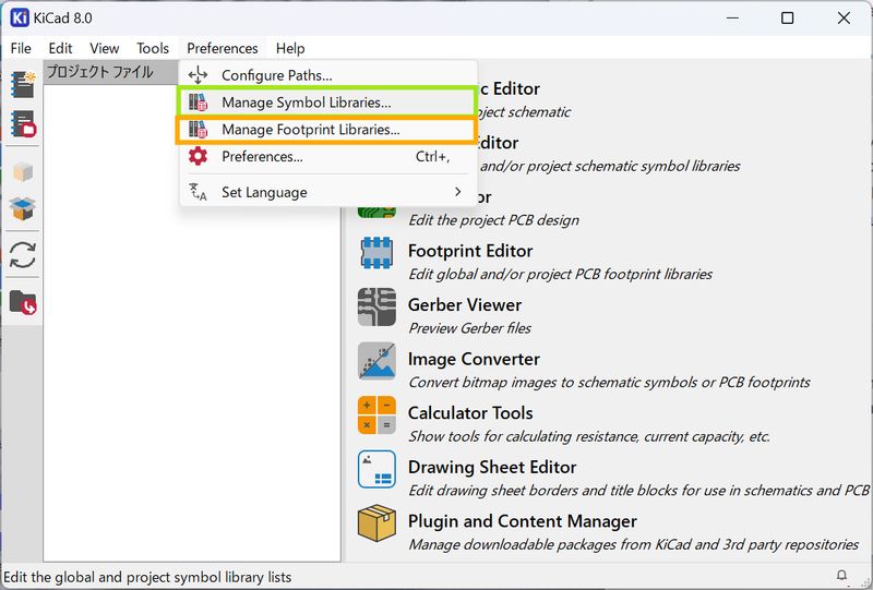
There are 2 important libraries.
- Add Symbol Libraries (for Schematic Design)
- Add Footprint Libraries (for Board Design)
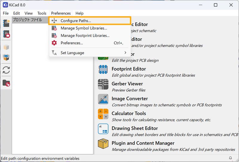
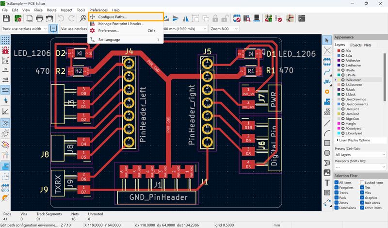
Finally, set Configure Paths to point out the location of the fab library

Design Trial
Then, I tried to use it first. I tried to make the fundamental board, which contains necessary parts Rico-san mentioned in the session as below:
- power LED: To check the current - if the board is receiving power correctly
- debug LED: To check the signals - if the program is being loaded correctly (for example, you can set it to light up at the beginning or middle of a program to check if the program is loading correctly)
- reset button
- extra pins - GND, VCC
- programming pins
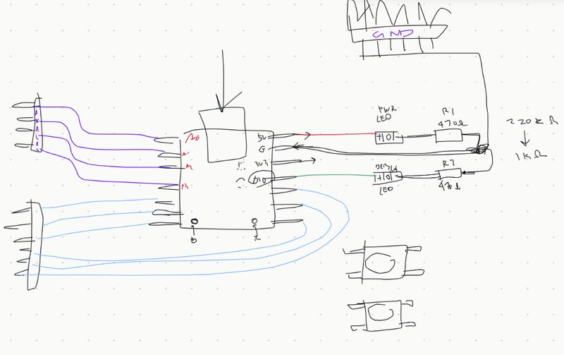 (The
sketch was also done by Rico-san)
(The
sketch was also done by Rico-san)
I also checked: Fabxiao by Adrian
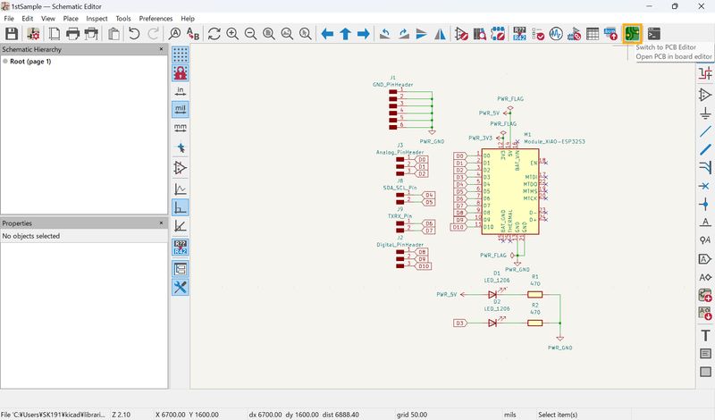
Schematic Design
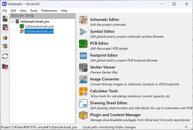
After creating new project, go to “_sch” file.
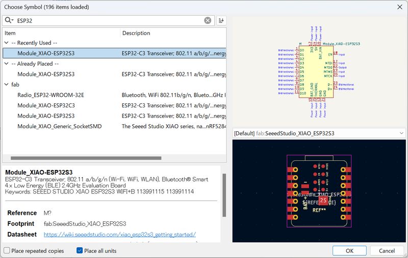
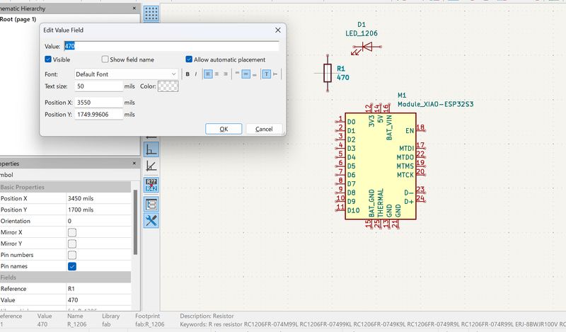
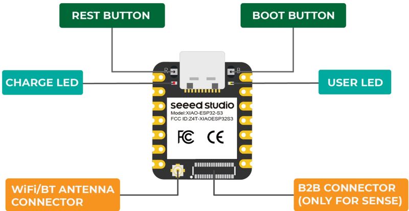
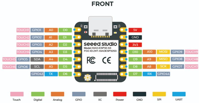
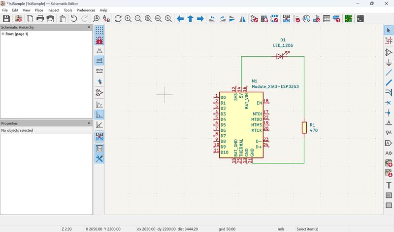
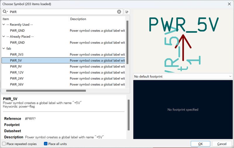
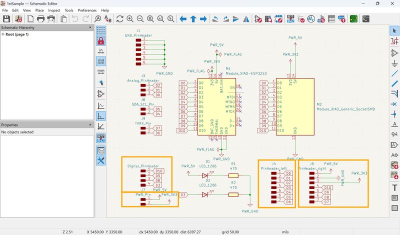
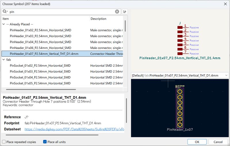
Press A to add components. First, I tried with xiao. Searched ESP32. There are 2 versions. I choose Seeed Studio XIAO ESP32S3

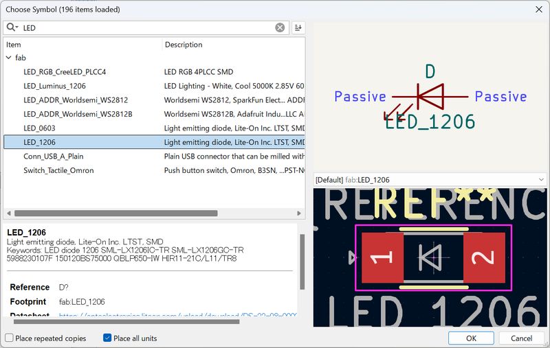
Add a power LED. There are many kind of LEDs, and I was confused, but tried something
seems basic.
Also add a Resister.
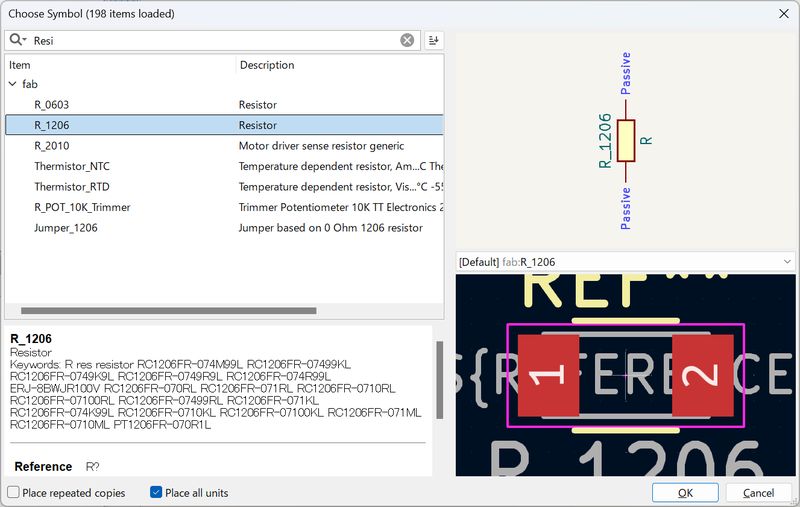
Press V to add value to the Resister.
To connect it, I checked the datasheet. I was confused because the pin arrangement on the circuit diagram was different from the actual pin arrangement.
When I tried to connect it, I accidentally connected the part to a pin I didn't want to
connect, so I changed the orientation of the part.
Press R to rotate the parts.
Press W to wire it.
Then, add debug LED. Do the same steps.
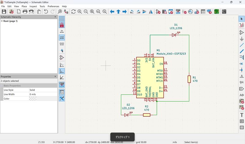
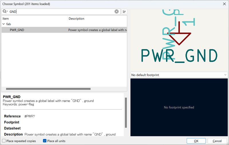
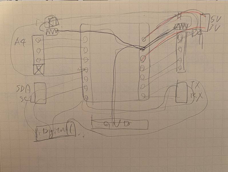
It seem it might become complected. Suddenly, I remember the session and I noticed, I don’t have to connect it physically. I can use GND or Power symbols!!
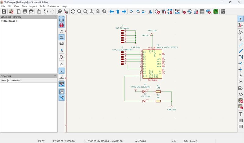
Then, I shared the image and I’ve got the advises:
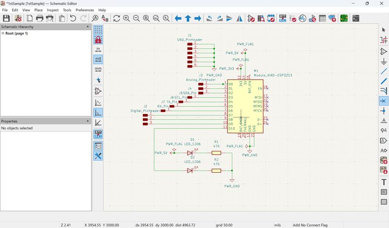
- separate the digital and analog header pins into 2 different groups
- separate pin headers for the TX (D6) & RX (D7) pins, and the SDA (D4) and SCL(D5) pins
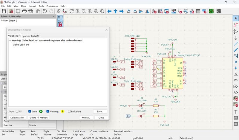
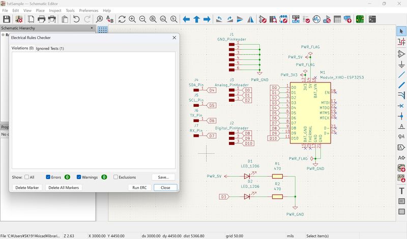
To add markers, CTRL + L
Run ERC, and got so many errors… It seems the green wire line not connected.
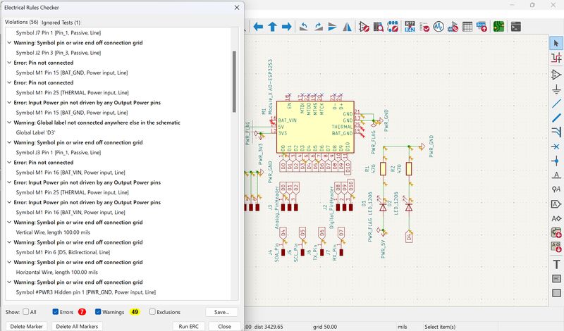
I’ve got additional advices, and I modified:
- should use a 2-pin header...not a 1-pin header for SDA and SCL, TX & RX
- No need to add a PWR_FLAG for Power LED
I also mistook the pin number…
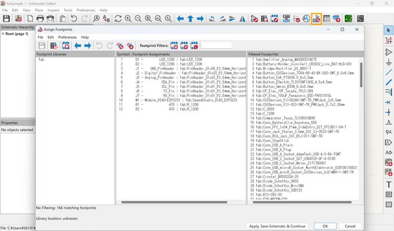
Check the footprint. Since I use components from fab library, all components have footprints.
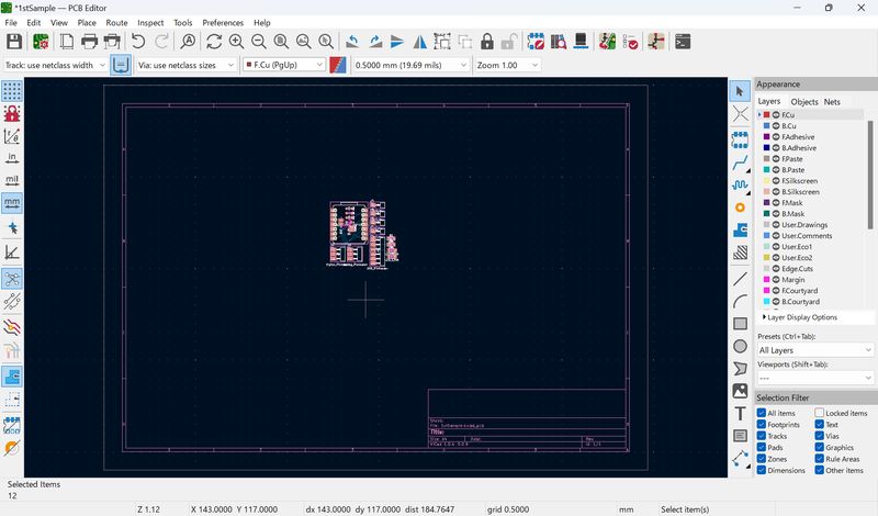
Then, go to PCB Editor
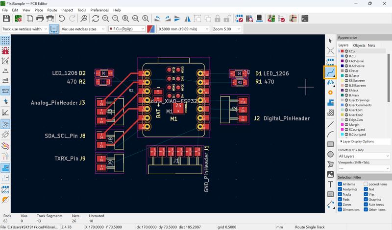
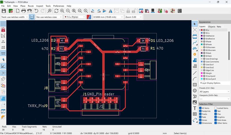
PCB Design (PCB Editor)
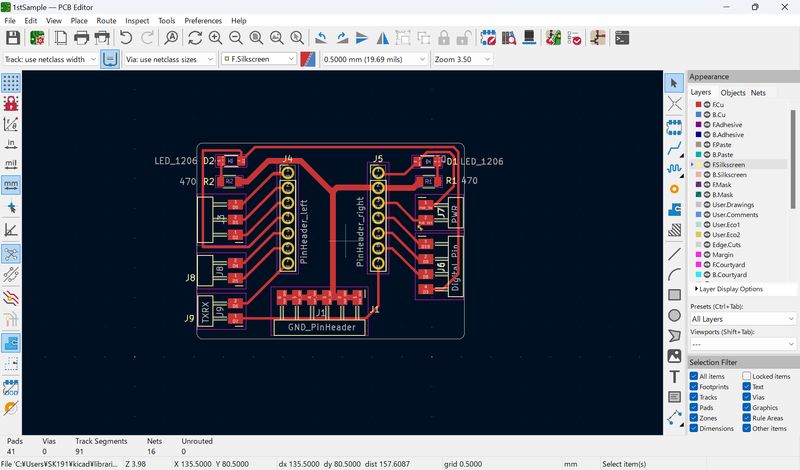
Press F8, and update PCB. The physical board I created as schematic show up.
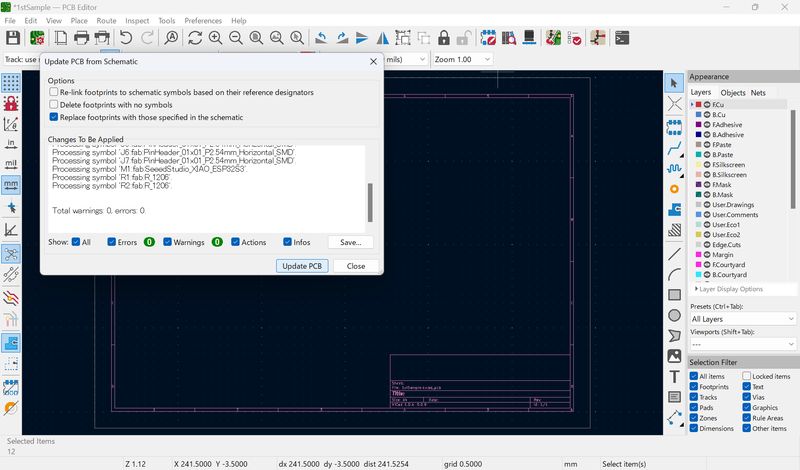
Seems wires are mixed up… I tried to check the original sketch and schematic design I made…
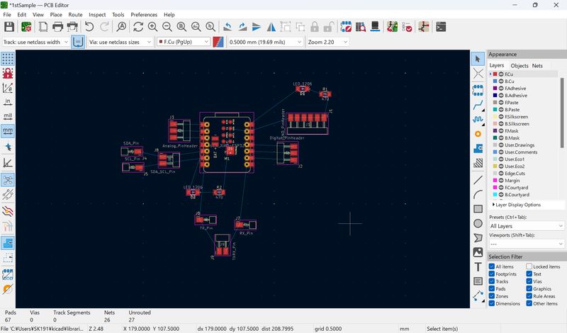
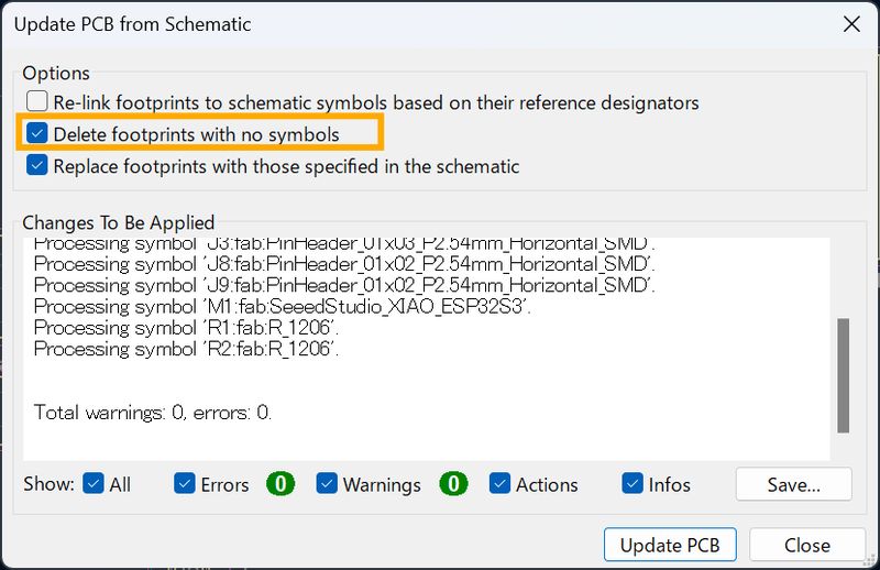
If you deleted some components from schematic, you have to “Delete footprints with no symbols”.
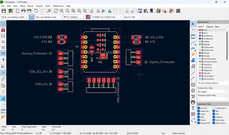
Now it seems better. Let's try to wire it. Before that, have to check design rules.
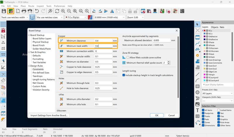
Design Rules
Design Rules: Constraints on how skinny the wires should be, or how close they can be,
etc.
To set this, go to Board Setup, and choose ”Constraints”.
In class, it was said that 15 mils is good if you make the board in-house. This corresponds
to 0.381 mm, so I set them at 0.4mm.
Set Minimum clearance: 0.4mm,
Minimum track width: 0.4mm.
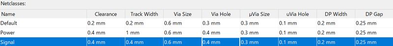
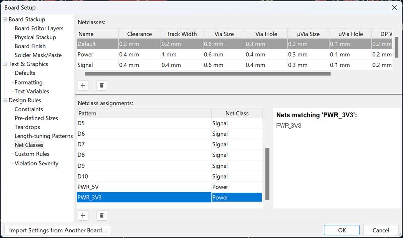
Then, go to Net Classes.
The default setting is too narrow a gap. We have to set it. This is also good for
distinguishing.
In the local session, I’ve learned Signal lines should be thin, and Power lines should
be thick (to reduce resistance).
I set Power and Signal lines as below:
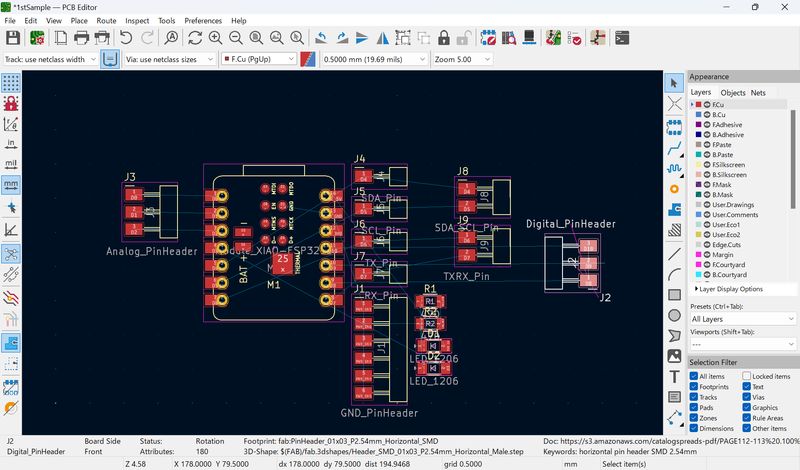
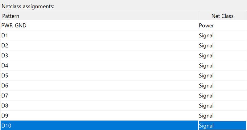
Then, assign Netclass for each pins:
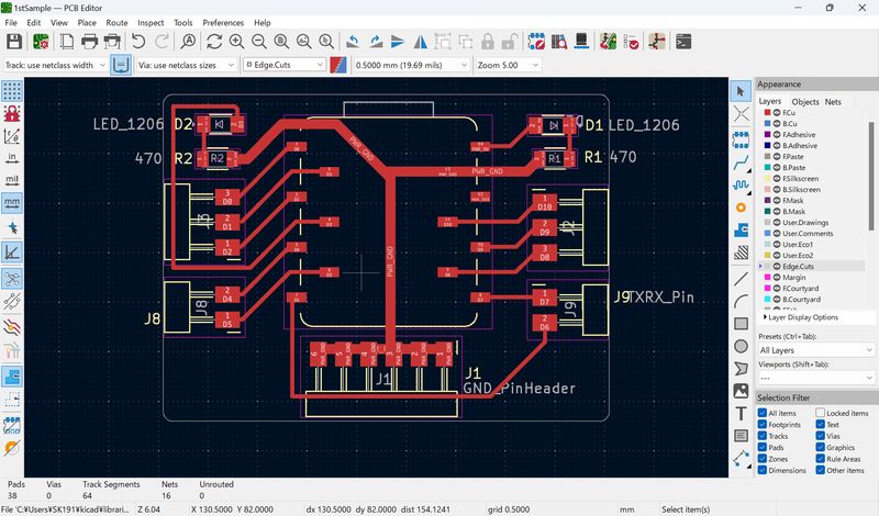
Then, wire it with Rout tracks. In Kamakura, we use only F.Cu
layer.
Press X to Draw line.
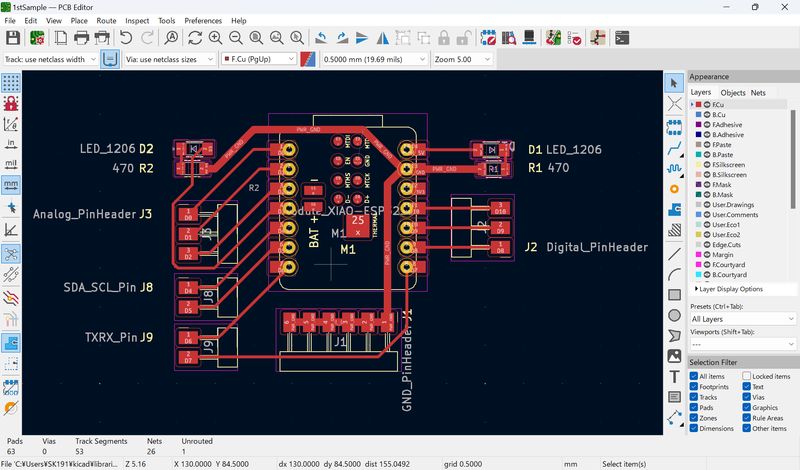
Draw outer line
Choose Edge.Cut layer and Select shape tool you want and draw line. (At First trial I choose B.Courtyard layer and couldn’t cut)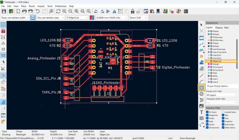
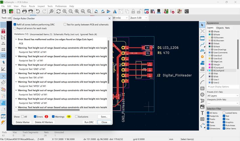
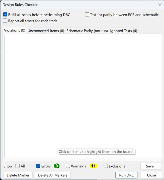
It seems there are some errors again. Run DRC. I checked some connections and tried to delete “errors”.
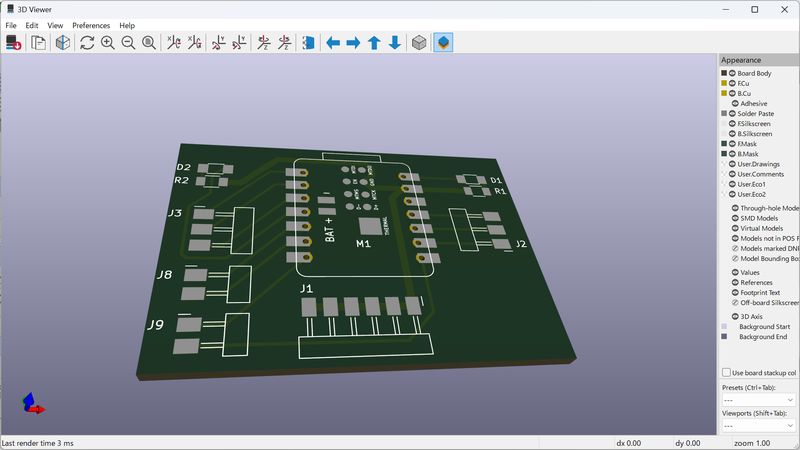
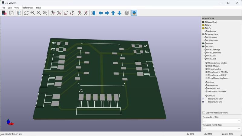
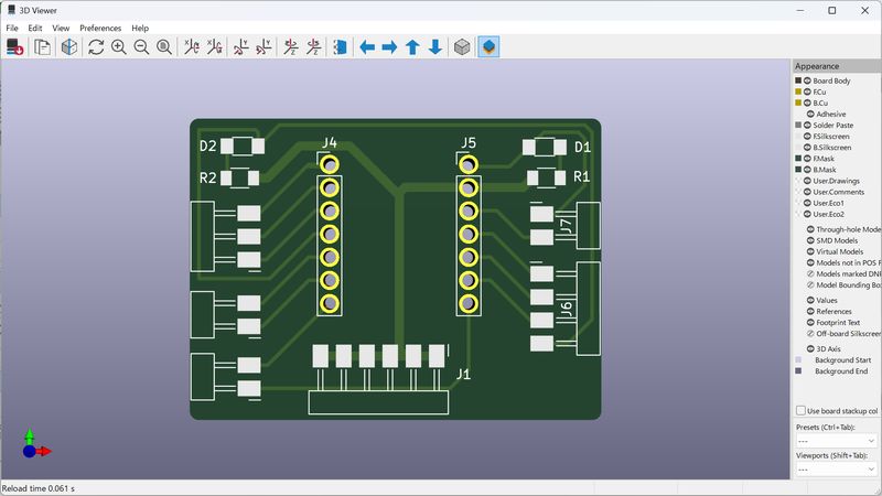
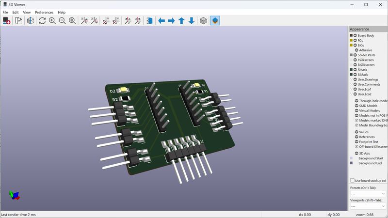
Go to 3D Viewer, now it becomes 3D!

Then, I’ve got some additional feedbacks.
With feedback, I modified some points both for schematic design and board design.
- LED and Resistor: place slightly further
- Female socket connections: need to be rotated
- LED: go around instead of under
- Recommend to use socket(so that I can change to RP2040 or other xiao board(xiaos have the same pinout!!))

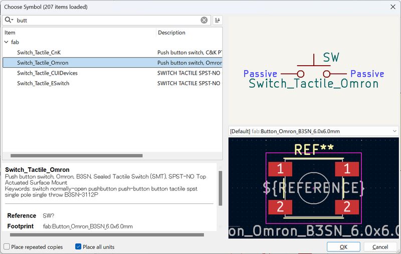
Try to add button, but no more pins...
I made it almost symmetry(for the parts).
Refine the design
From what I learned from a session on the lab, I changed some points…
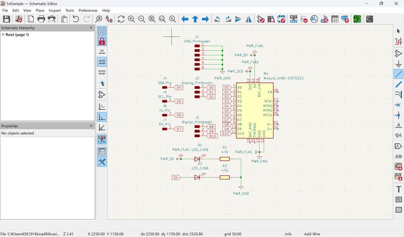
- I can use pins for multiple use: I changed digital pin header for 4 holes, and added power pin header.
- We might not have the xiao socket in FabLab Kamakura inventory: changed to the hole.(I noticed that we have to consider about items in inventory also.)
The parts enclosed in orange square brackets are added in schematic editor.
For digital pin header and power pin header, I used the same connectors as 1st trial but with different numbers.
For xiao socket, I used 7 hole passive connecter (There are 2 sizes, I have to re-confirm the size of pin header for xiao)
In PCB editor, I didn’t change any design rules, but changed the layout due to the increase in parts.
Add 3D model of components
Thanks to Saheen, I've learned that I can add 3D model of components with the following steps in Asian review session:
- Open configure paths in preference
- Add Name 'FAB' ( important to keep exactly the same )
- Then select the path from the cloned fab library

Finally, I also notice that Power line is not bold.(I noticed this when I saw the other
members discussing corrections.)
So I assigned Netclass for 5V and 3V3 pin.
The lines are too close to D4 pin line, so I fixed them.
Outcomes
- Sample.kicad_pro (project file)
- Sample.kicad_sch (schematic design)
- Sample.kicad_sch (pcb design)
*Project name is sample, but this is the final design for this week.
This week I tried KiCad. Since I could get good instructions, and also could use fab
libraries, it was not too much difficult. It was much more difficult to think how to
structure the final project… I have to continue consider about it to (at least) print
out the board.