#5 3D Scanning and Printing
This week I learned how to design, scan and print for 3d object.
Assignment
Group assignment
Individual assignment
- Design and 3D print an object (small, few cm3, limited by printer time) that could not be easily made subtractively
- 3D scan an object (and optionally print it)
Outcomes
What did I do this week: 1. Group Assignment
The group assignment page - week05
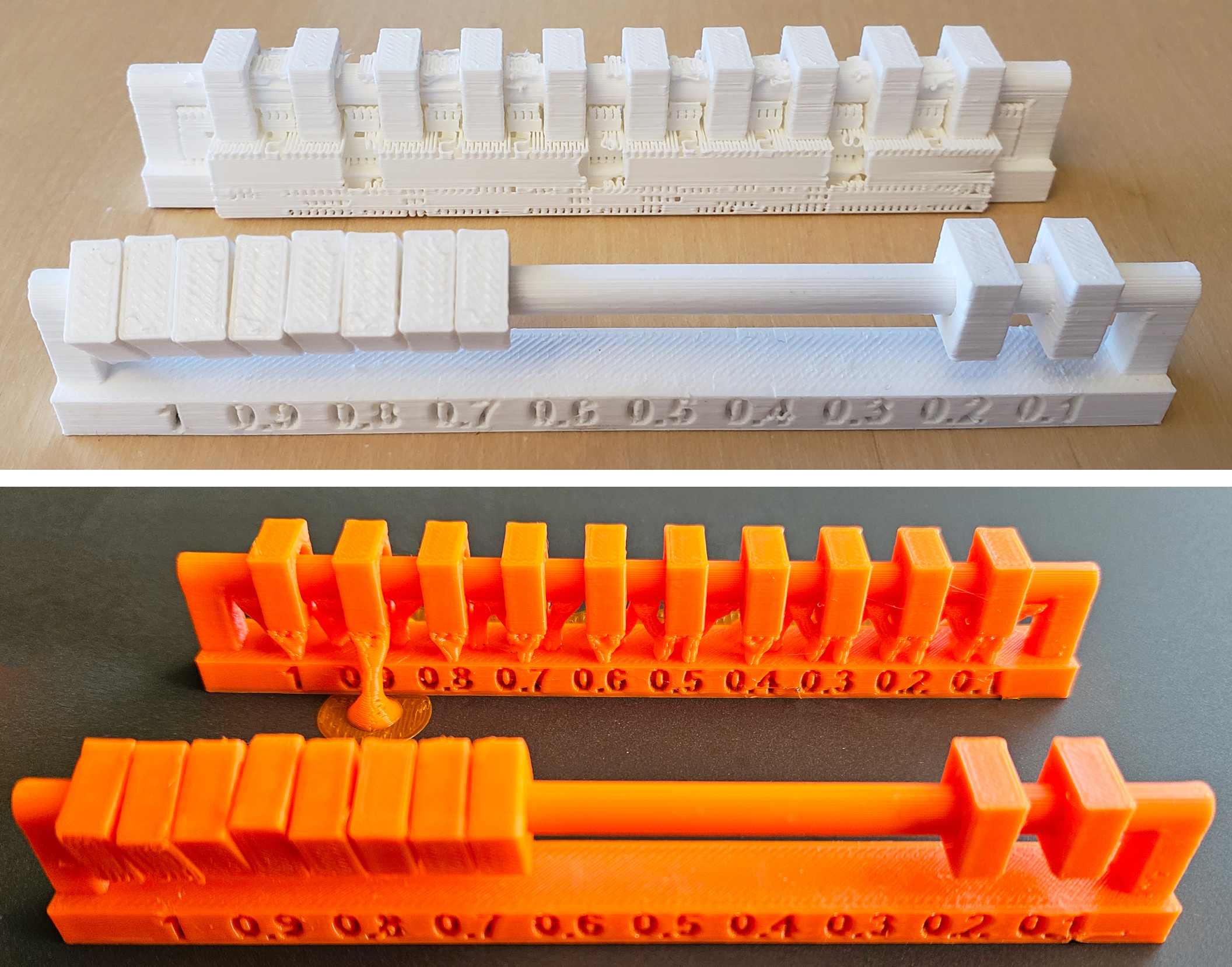
Test the design rules for your 3D printer(s)
To test the printer, we printed two pieces of data below:
All In One 3D Printer test 2.0
clearance test data in the class page: FCStd
jpg
stl
When printing, you will need to set the following
items:
(It was a bit confused point that the differences between Brim, Raft, and Skirt.
So, an
explanation of each item are written in the notes section below)
| Item | Value | Note |
|---|---|---|
| Infill | 15% | On the test model page(All In One 3D Printer test 2.0 by Zipolla - Thingiverse), it said to test with infill: 100, but for general printing, set infill: 15~20, and test in the same environment as my normal printing is needed, so we tested with the value |
| Infill pattern | Grid | I later learned that Gyro is better. Grid
patterns
tend to accumulate dirt at the intersections. It is necessary to choose the
appropriate
infill shape depending on the shape of the model. (So I used Gyro for my personal assignment. ) |
| Skirt | 2 | Creates a frame around : Used to prevent filament stains that appeared at the beginning |
| Brim | None | Can be surrounded : Used to strengthen and stabilize the adhesion of the edges of the part |
| Raft | 0 | Creates a base : Used as a base when the surface to be placed on is small |
| Support | None | For parts other than test model, it is important to set the support according to the shape. |
| Speed | Default | Anycubic: 230 Creality Print/Bambu: 60 for the first layer, 300 for inner and 200 for outer for the following layers You can print beautifully with the default settings. You can adjust it to speed up depending on the model, but more than 300 is not recommended. The above is for PLA. PET-G will adhere better if it is a little slower. |
| Travel | 500 | Normal moving speed for areas other than the printing area. |
| Layer Hight | 0.2 | 0.2-0.28mm is common, 6-70% of the head size is optimal |
| Wall | 2 | How many walls will be made inside the structure |
*Regarding temperature:
PLA melts at the lowest
temperature: 190-210°
High-speed printers need to set the temperature higher. (If it
goes too fast,
it won't melt.)
*To prevent oils from your hands from staining the
printer bed, wipe it with alcohol or similar after use.
We all shared the printing results and recorded them.
For details, please see the group
page: The group
assignment page - week05
What did I do this week: 2. Individual assignment
Design and 3D print an object (small, few cm3, limited by printer time) that could not be easily made subtractively
Research and Design
First, I looked at ideas on Pinterest to
see what
kinds of additive design are possible. As I looked, I came up with two ideas.
One was
to add a
mantle to the globe I had made before in week 2, to create an expression that could only be
achieved
with additive design. The other was to create something that looked like soft cloth. (I was
interested
in the T-shirt prints descried in class.)
I thought that an output that was closer to
the final
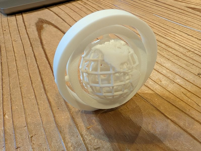
assignment would be better to think about it, so I decided to make a globe with additive
design.
I
was able to get a variety of design ideas during the local session, so I decided to add Gyro
to make it
more "globe-like." I was also interested in Voronoi Lattice, which is also
introduced in the
session, and since it seemed like a good way to express the mantle, I decided to give it a
try.
- https://fab.cba.mit.edu/classes/863.14/people/andrew_mao/week3/
- https://www.youtube.com/watch?v=PWwJVcOWGRM&t=94s
- https://www.designboom.com/technology/nasa-space-fabric-4d-printing-04-27-2017/
- https://www.grasshopper3d.com/photo/3d-printing-fabric?context=latest
- https://jp.pinterest.com/search/pins/?q=additive manufacturing design
Why it could not be easily made subtractively?
Gyro: printed with nested parts as
assembled state.
The parts are formed in a combined state is a characteristic of additive design. In additive
design, a
gyro can only be made by combining separate parts.
Mantle inside the globe: Additive
design
allows us to
create the globe while the framework is still assembled. Also, the Globe (skeleton) are
printed with a
mantle inside. With subtractive design, it is difficult to carve the inside out from a single
piece of
material.
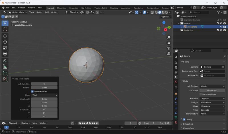
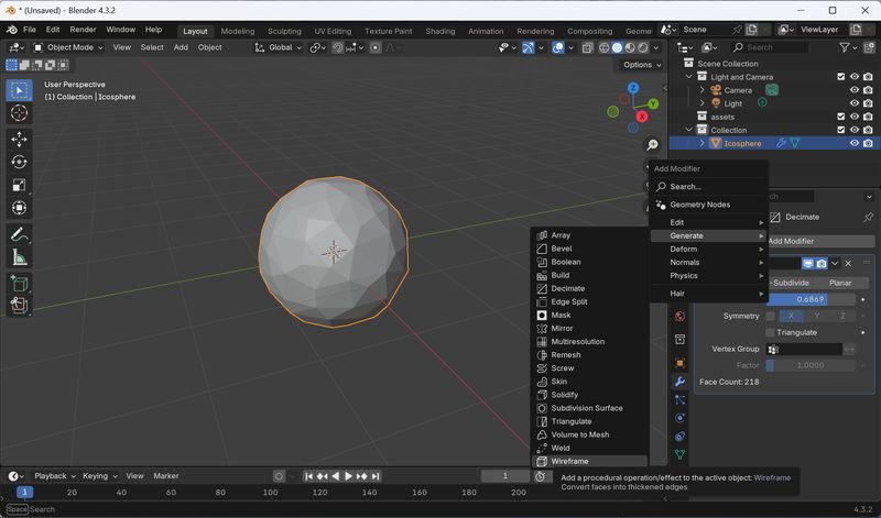
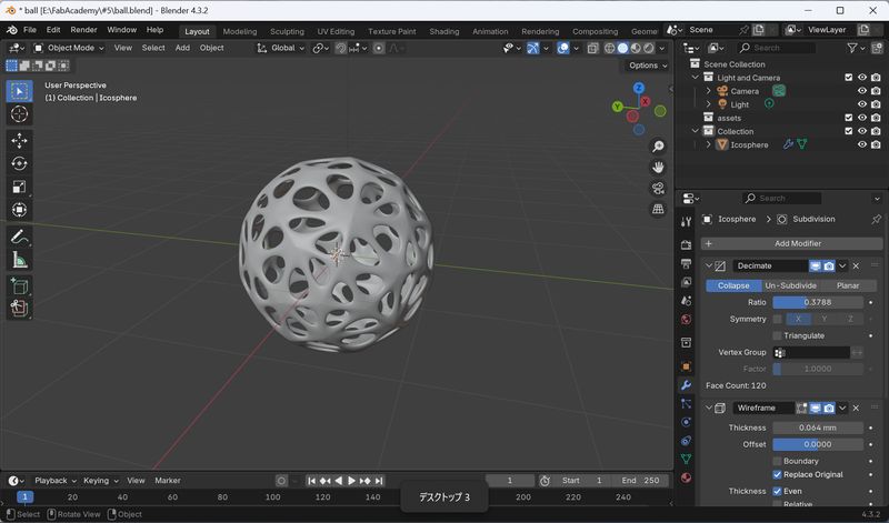
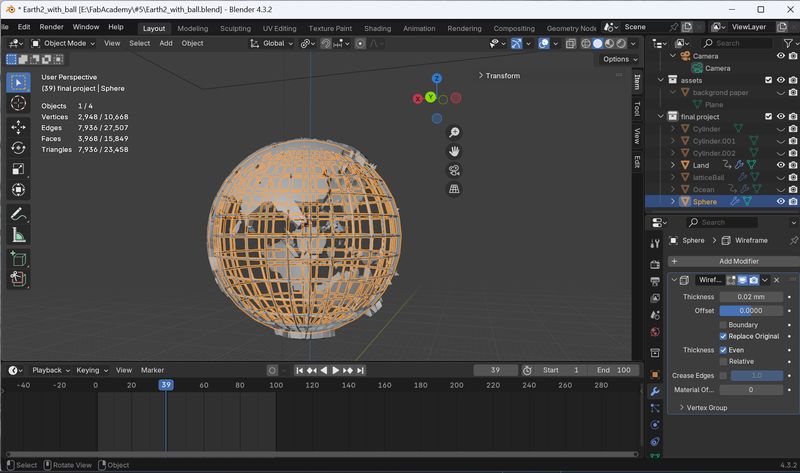
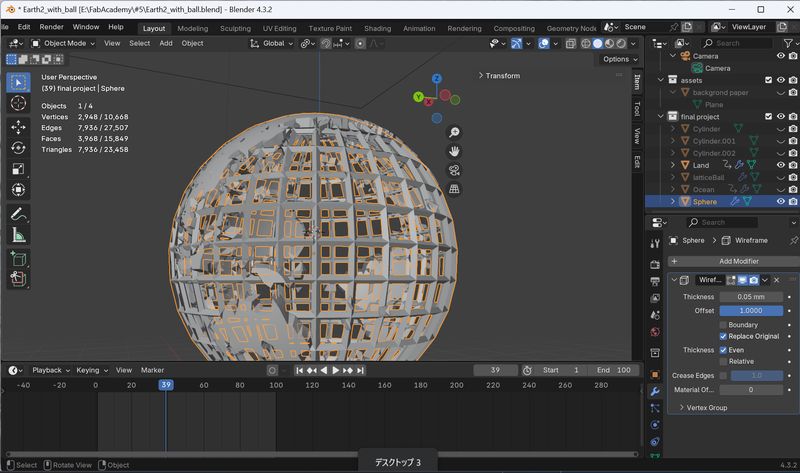
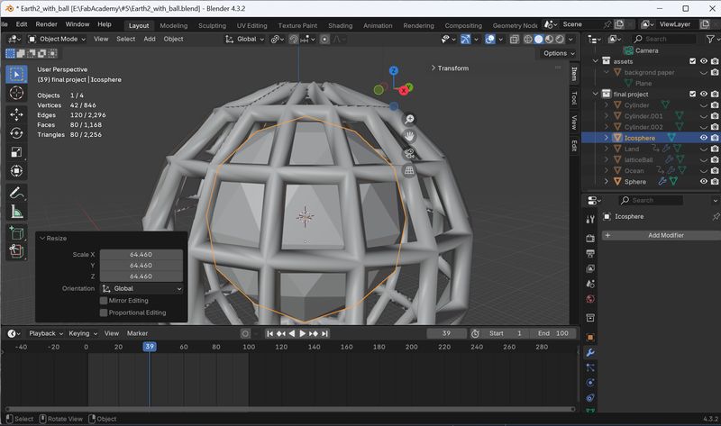
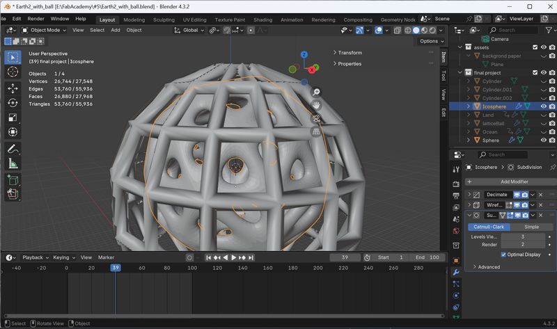
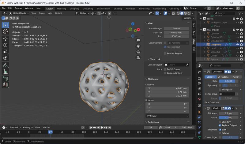
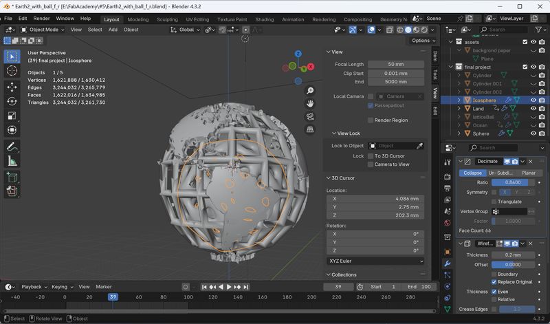
1. Voronoi Lattice Trial
In the Local Session, I learned that the Voronoi Lattice can be made by the following steps from Rico-san. I decided to follow that and create a round pattern like a mantle.
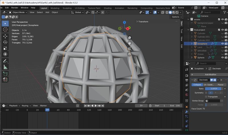
- solid geometry
- modifier 1: decimate
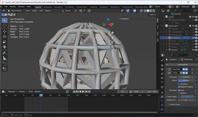
- modifier 2: wire frame
- modifier 3: subdivision surface
Add Icosphere > add modifier
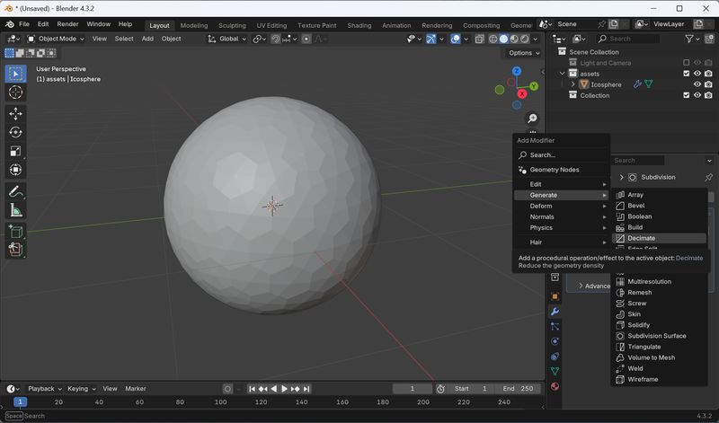
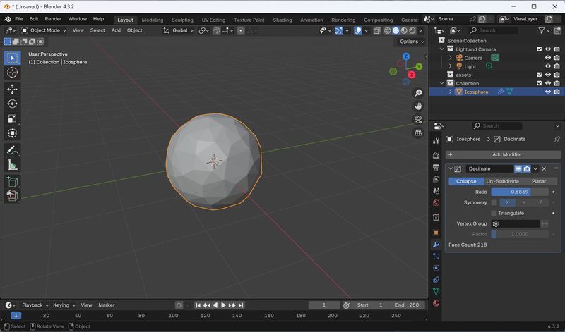
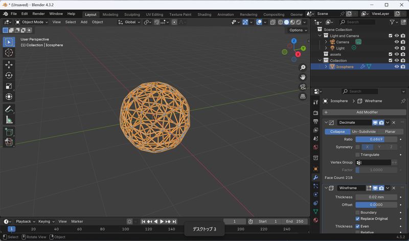
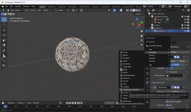
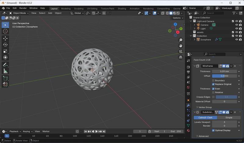
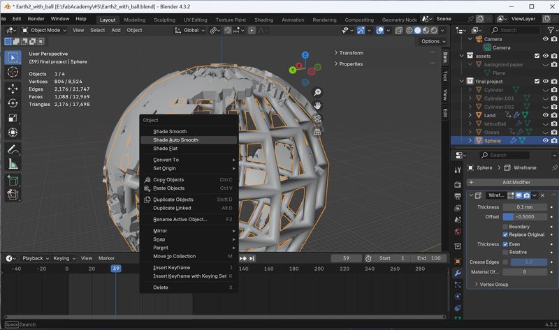
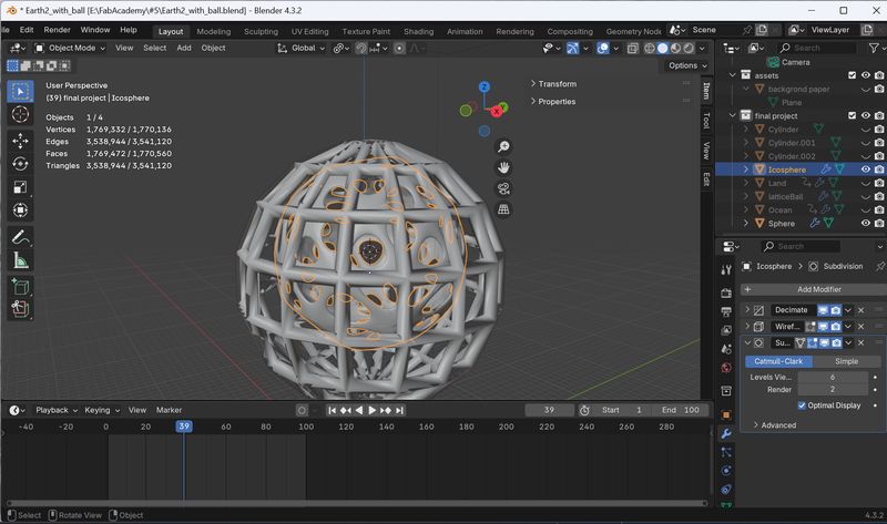
Adjust some parameters and make it looks
nice.
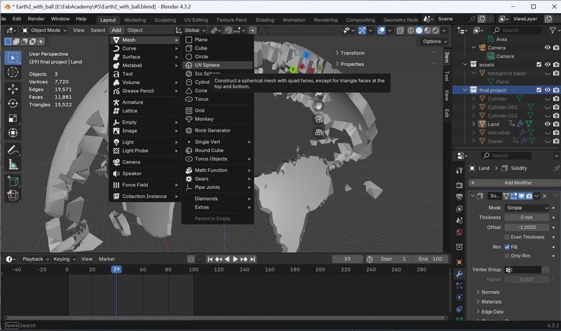
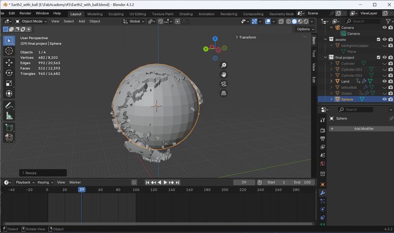
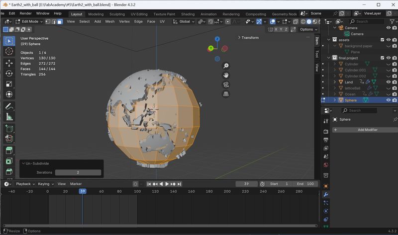
2. Modify Globe to print it
It was sooooooo much tough to take all of ocean part.
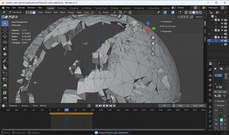
Add UV Sphere and Scale it to fit to make latitude and longitude.
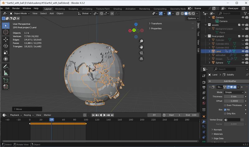
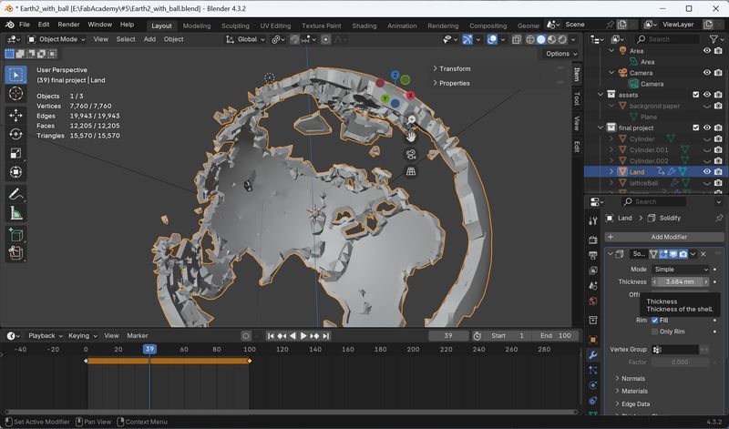
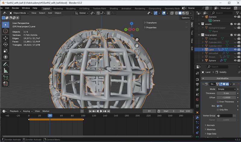
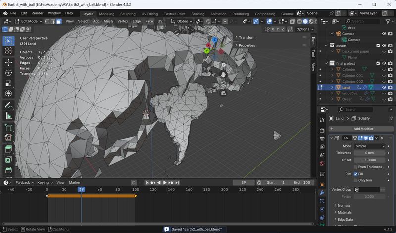
3. Add mantle inside
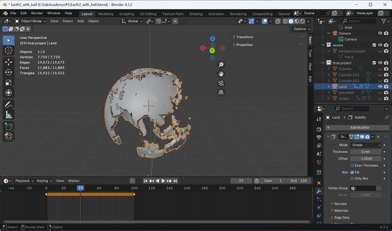
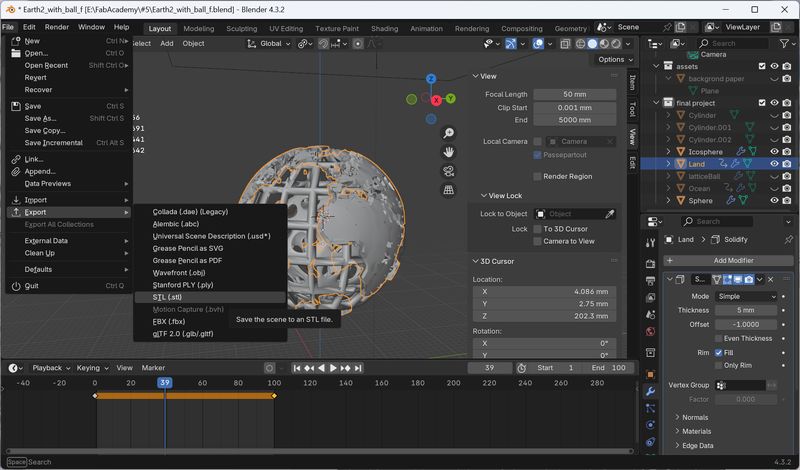
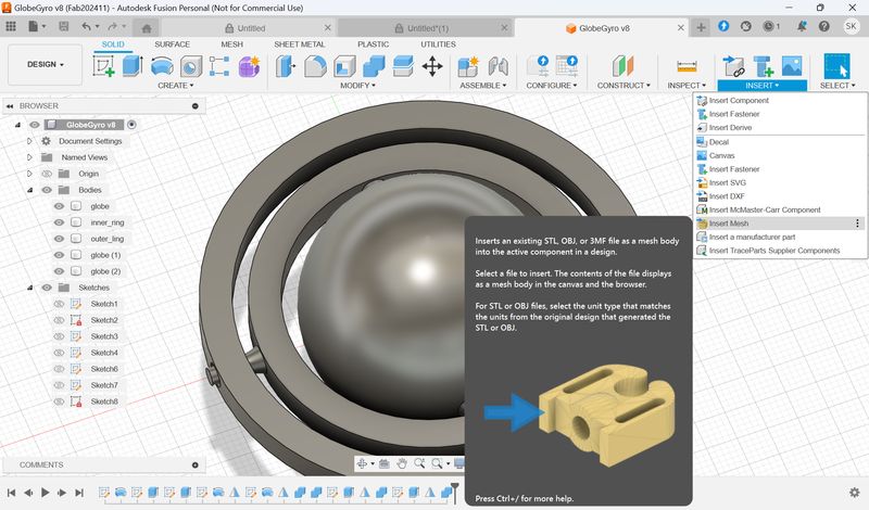
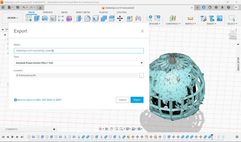
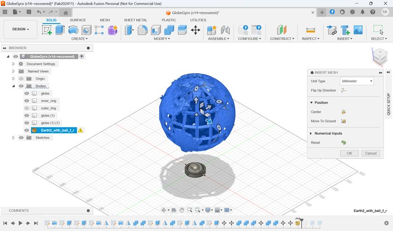
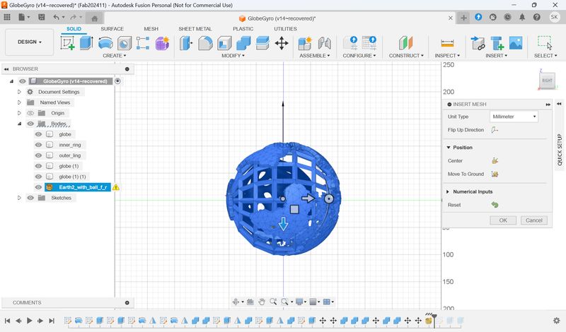
4.Export the data as stl
Display only necessary parts, and export the data as stl.
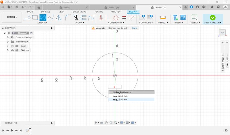
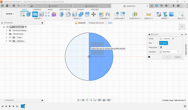
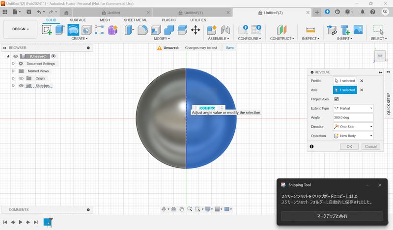
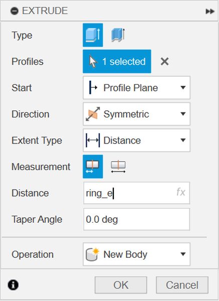
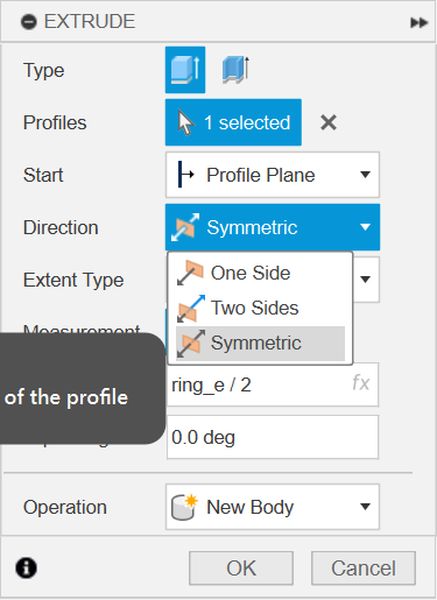
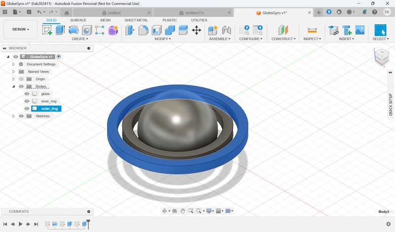
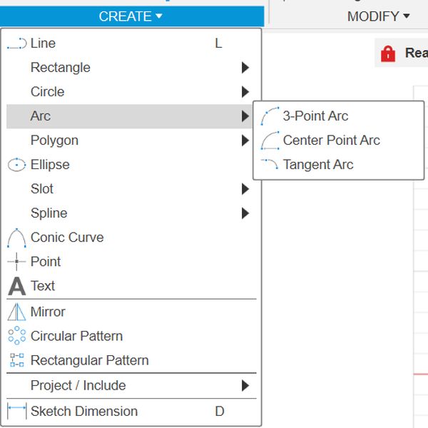
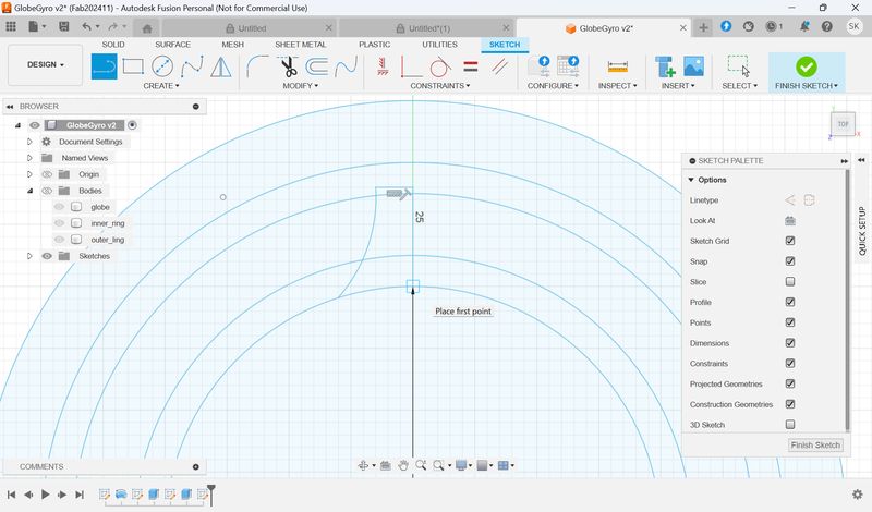
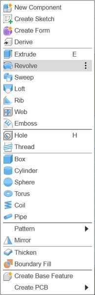
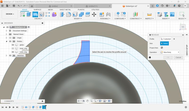
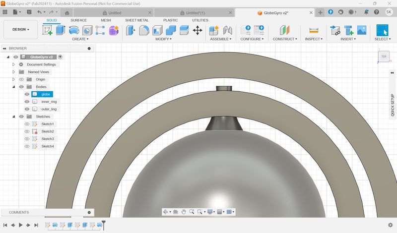
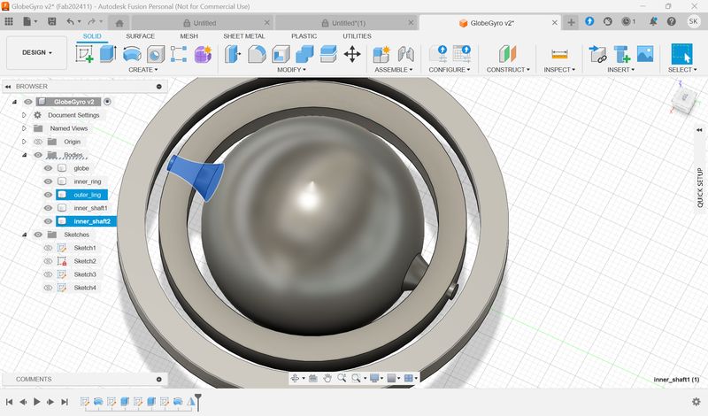
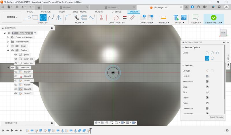
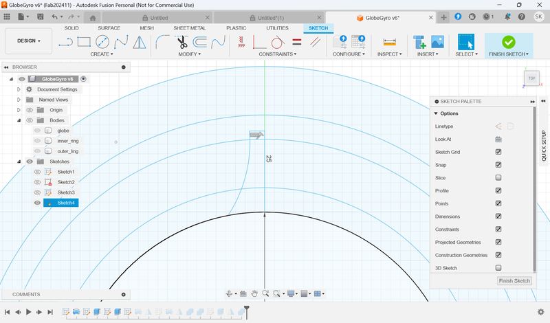
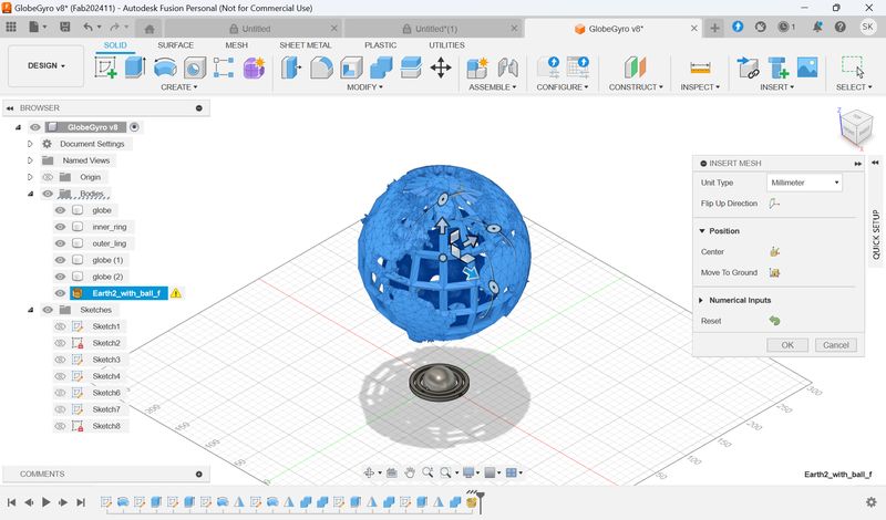
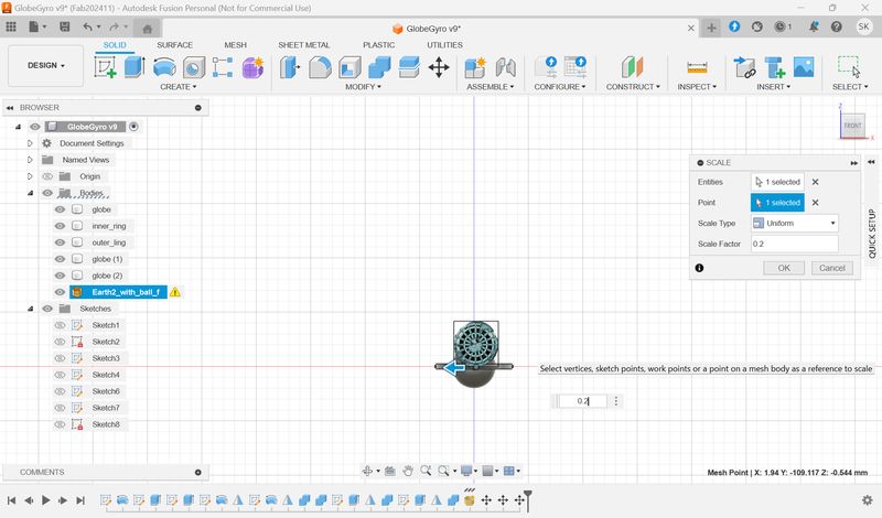
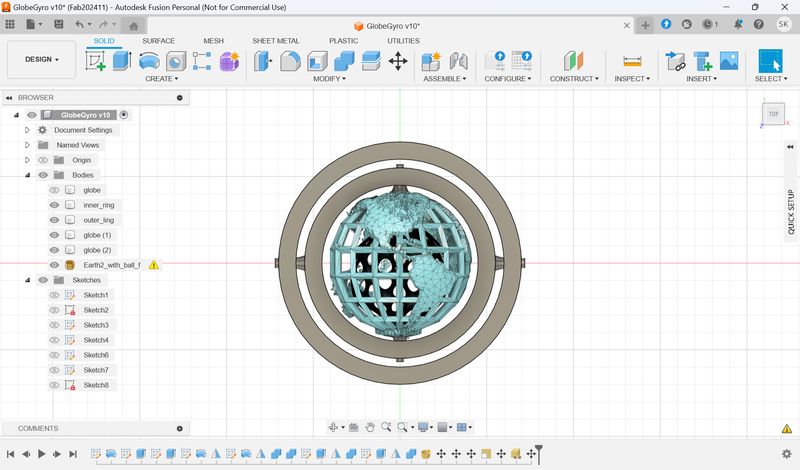
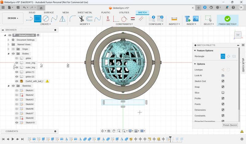
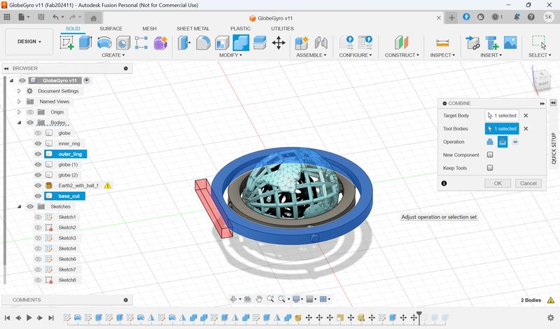
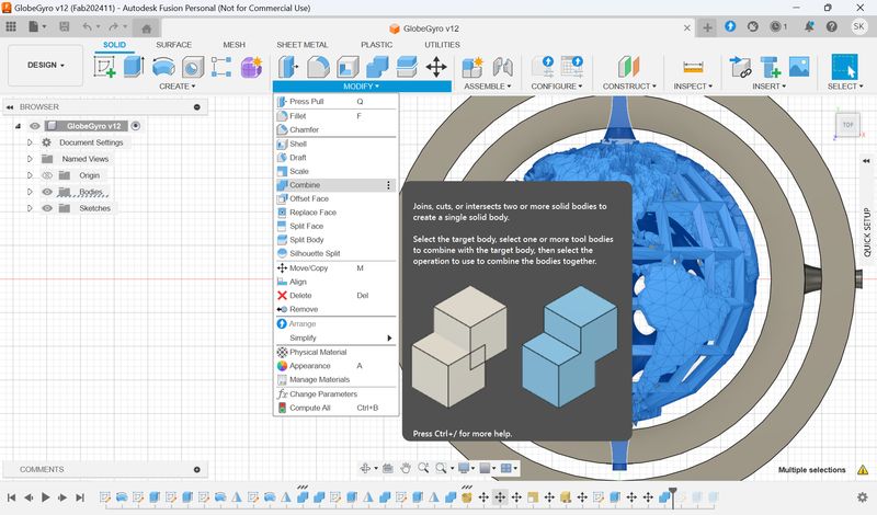
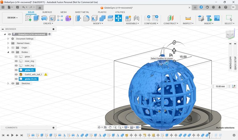
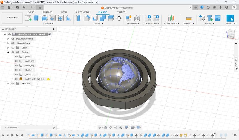
5.Make a Gyro(Fusion)
At first I tried to use the hole function to create a connection part for the two rings, but I had trouble drilling a hole in the curved part. The following was created while learning from Sophia, who work as FabLab Nomad.
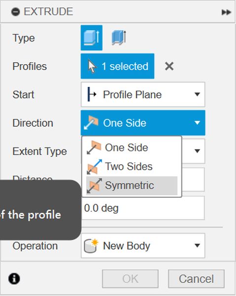
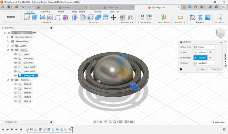
★The key is to have everything start from
the
center.
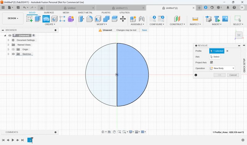
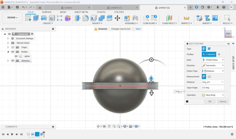
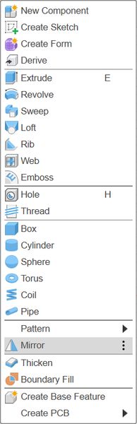
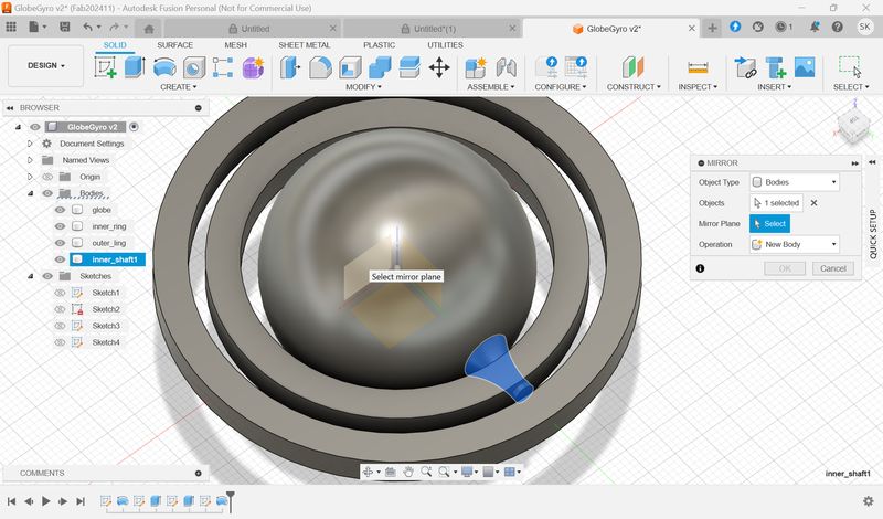
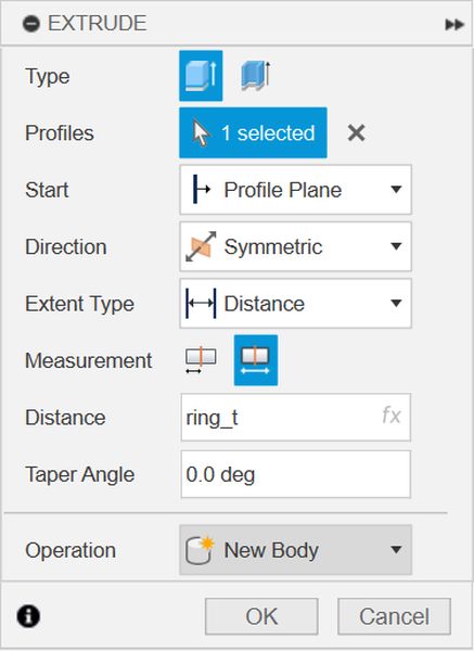
If you do that, you can make it symmetrical by setting Extrude to Symmetric or
selecting a
face with Mirror.
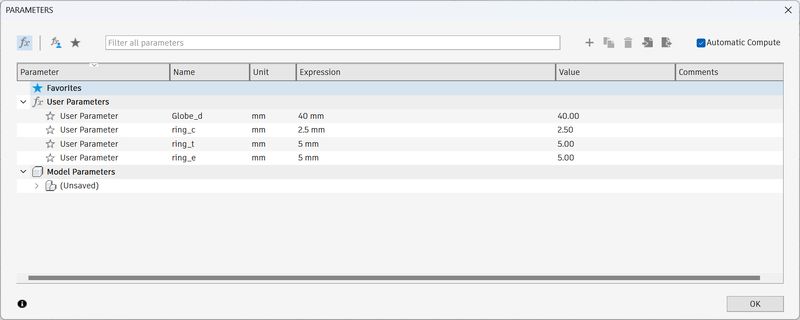
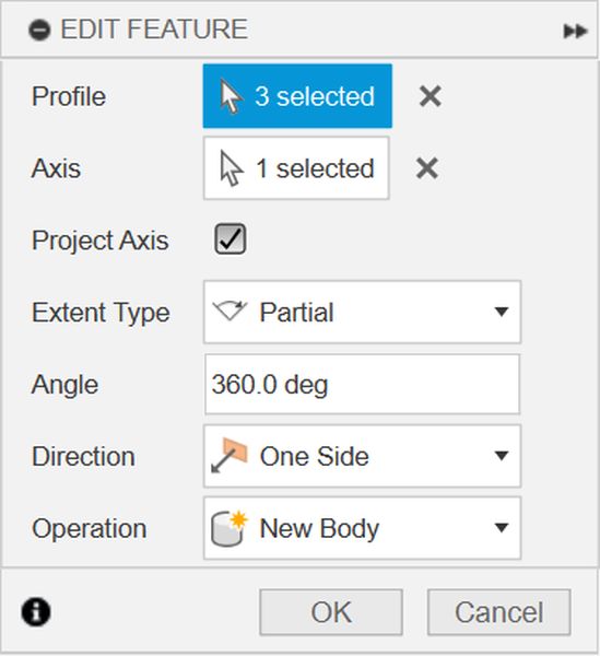
First I drew a design for the necessary parts and set the parameters
as
follows.
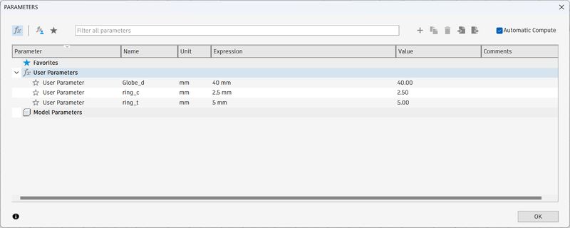
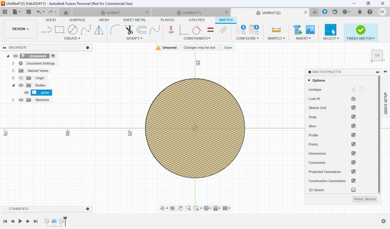
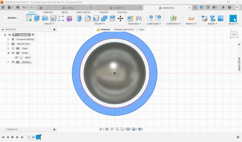
Create a Globe part to put Blender data into later.
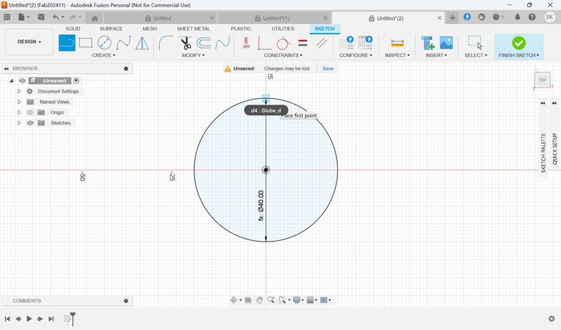
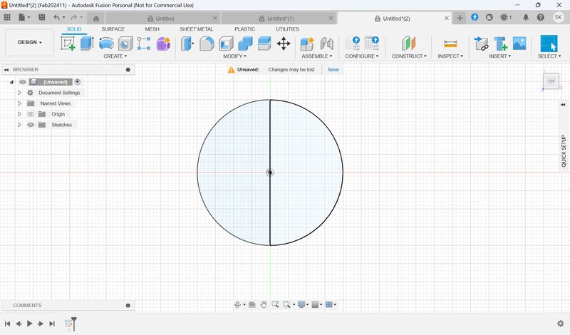

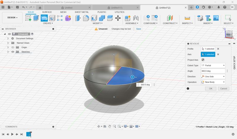
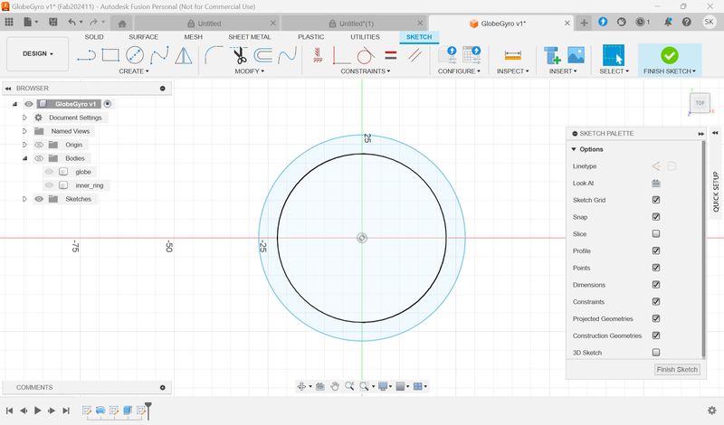
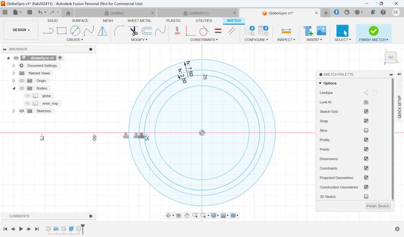
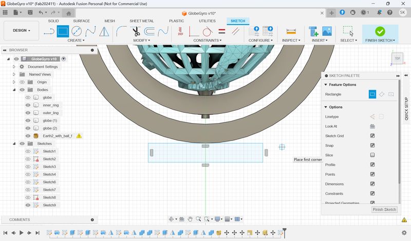
Make inner ring.
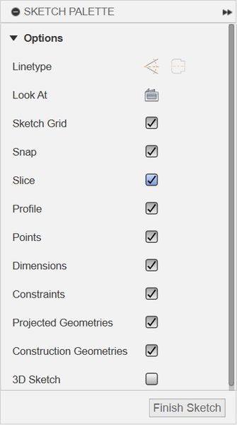
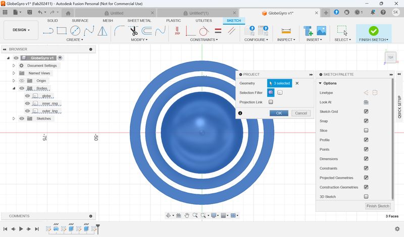
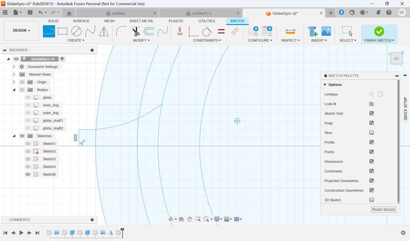
Create Sketch >
Sketch
Palette > Check “Slice”.
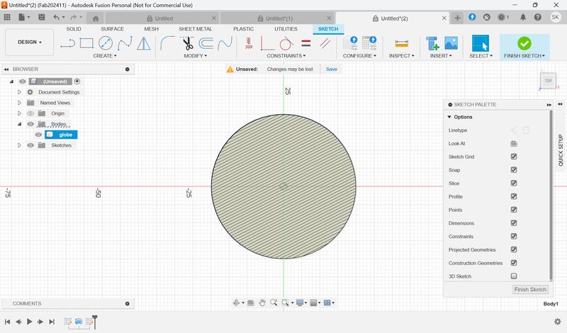
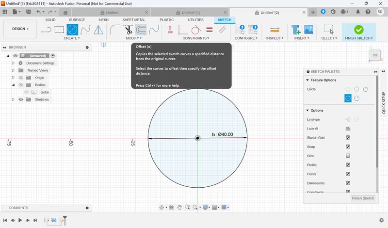
Press P = project. Uncheck Projection Link
Select Offset, and set the offset with the parameter.
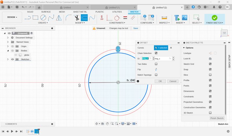
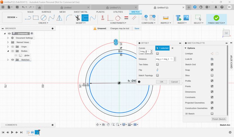
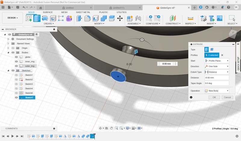
Add parameter for Extrude.
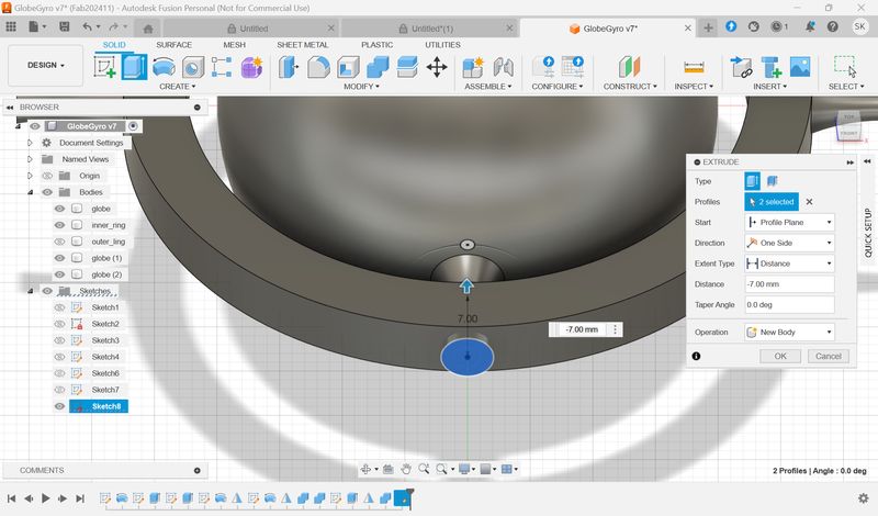
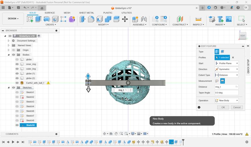
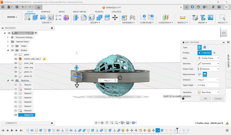
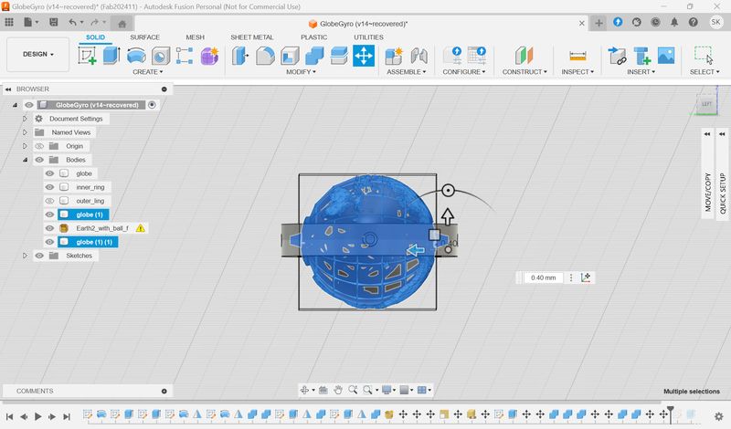
Make connection parts.
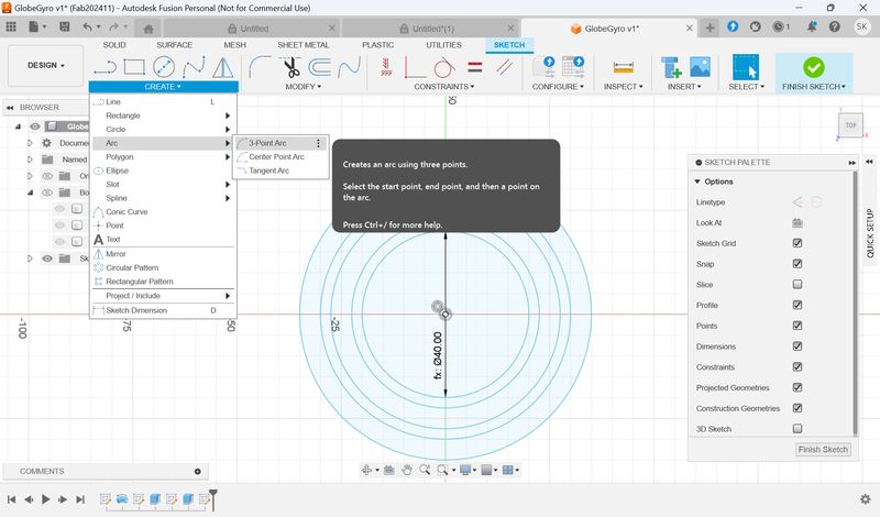
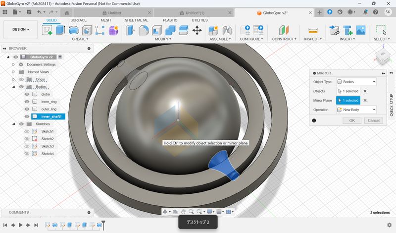
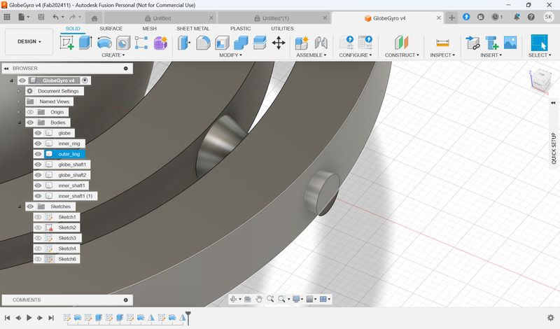
To make a sketch for hole, we need a plane. This time, we choose flat surface on the edge of the connection parts and create sketch.
If you want to adjust the shape, go back to sketch step, and choose the line you want to change and move it. Then go back to the current step.
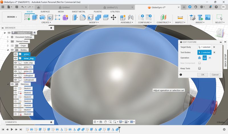
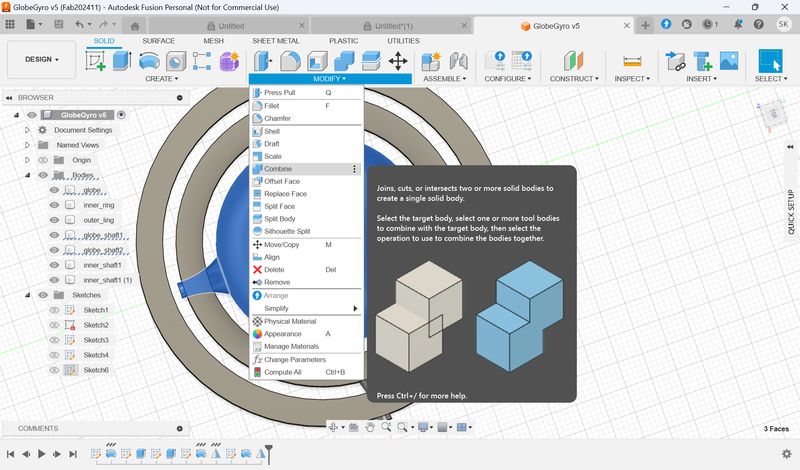
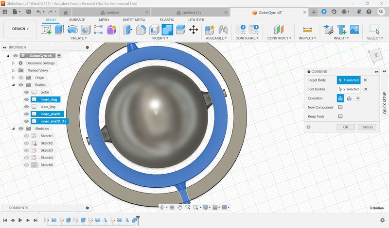
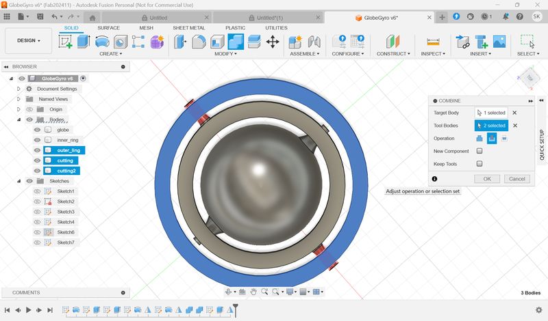
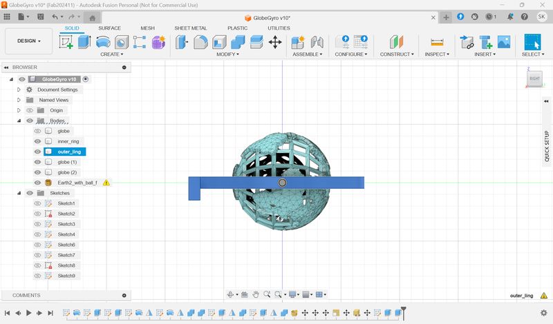
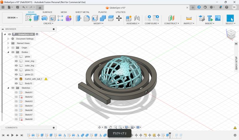
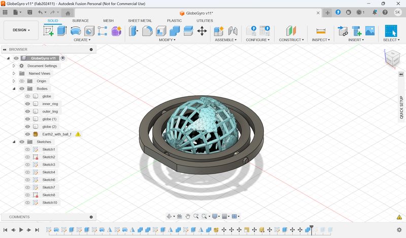
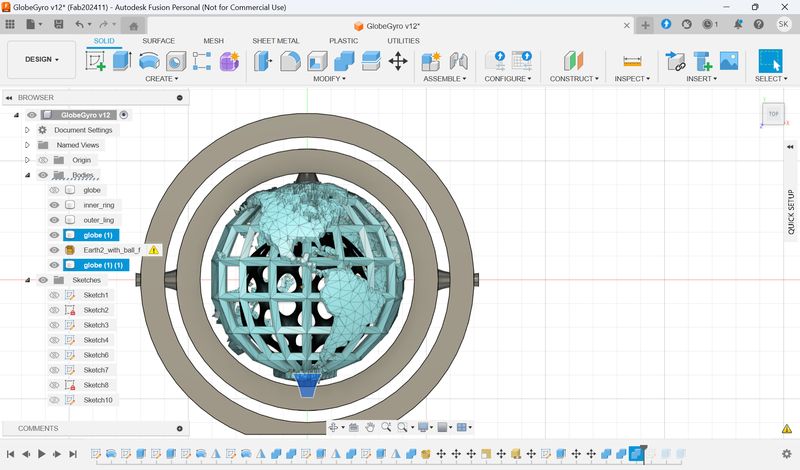
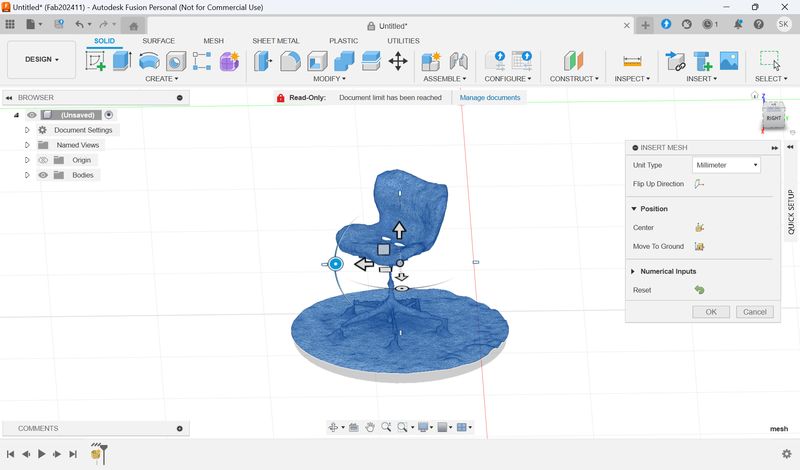
Convert the globe file and ring parts.
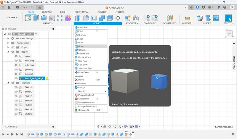
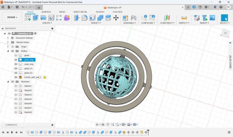
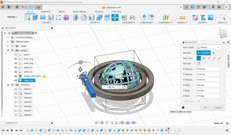
Make a cutout to make the ring stable.
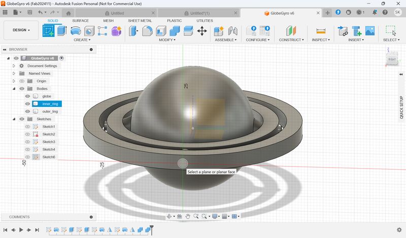
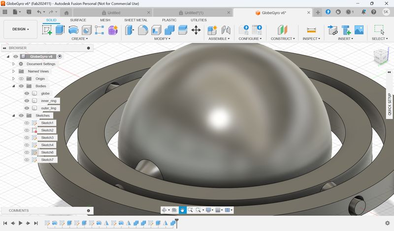
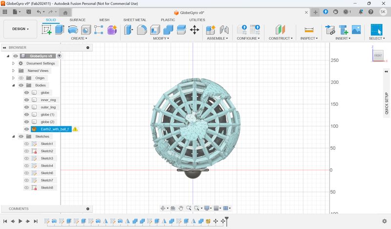
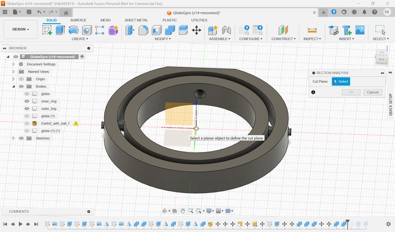
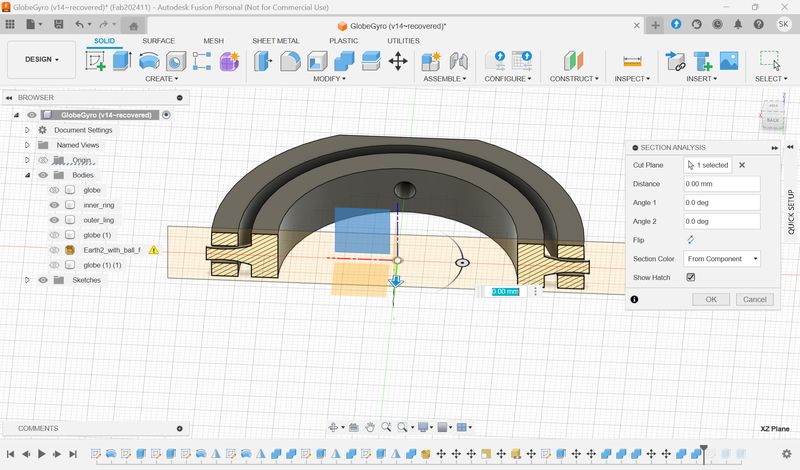
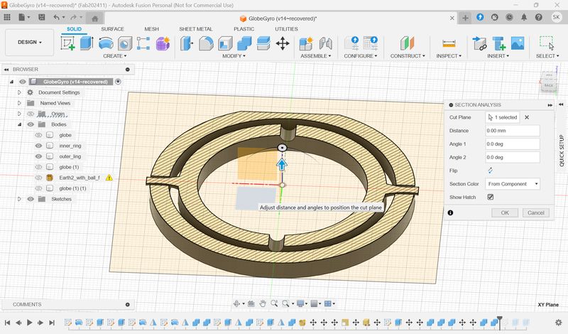
Section Analysis
You can check the cross-sectional structure. ① Select the surface you want to cut, and ② adjust the position you want to cut.
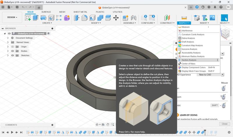
Then, I export the file as stl.
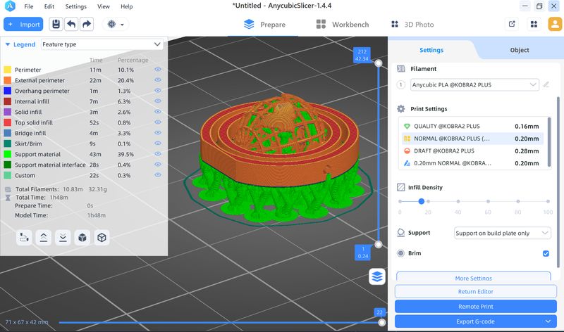
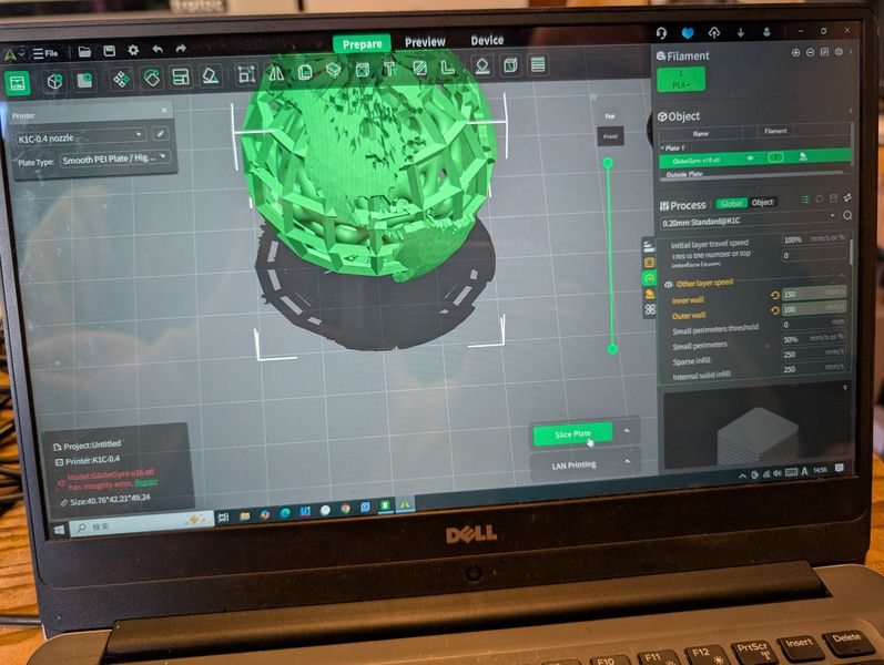
1st print trial
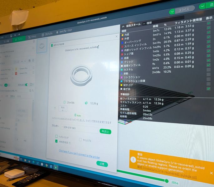
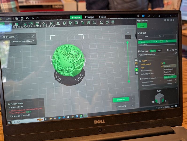
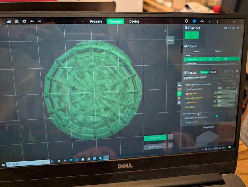
I open the stl file from slicer.
It
seems there are too many support if
I
print it at
once…So I decide to print them(Globe and ring) separately.
However, finally, I printed them one by one as different file. It is because structures affect each other when they printed out. (Recommended by Yamamoto-san.)
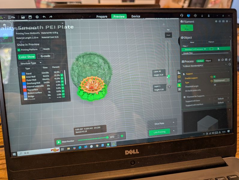
Export the data separately as stl. (Display only the parts I need and export)
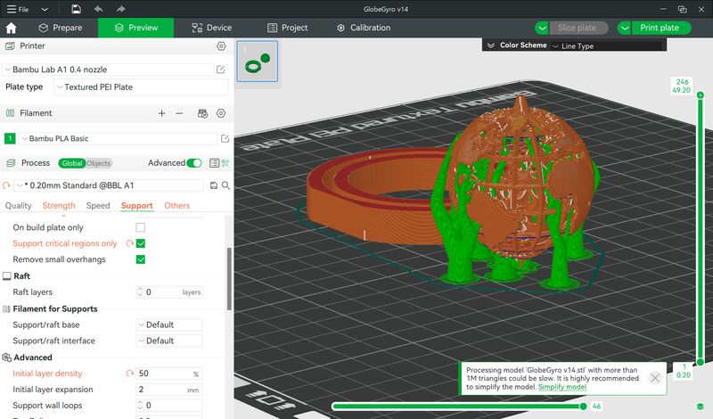
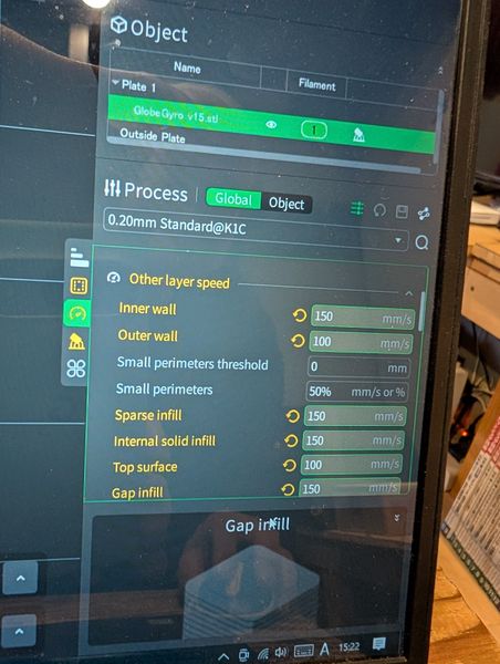
For ring parts, open in slicer and set the infill pattern as gyro, and otherwise print it with default settings.
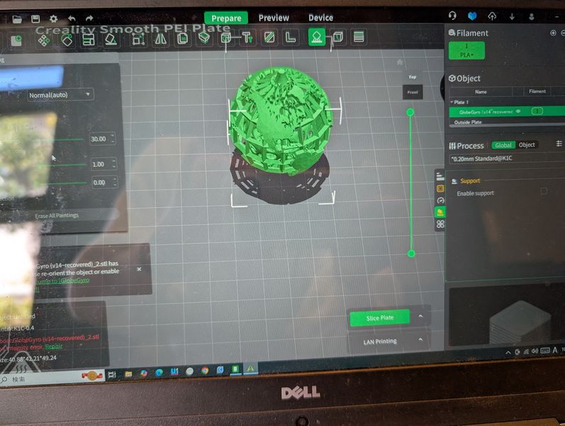
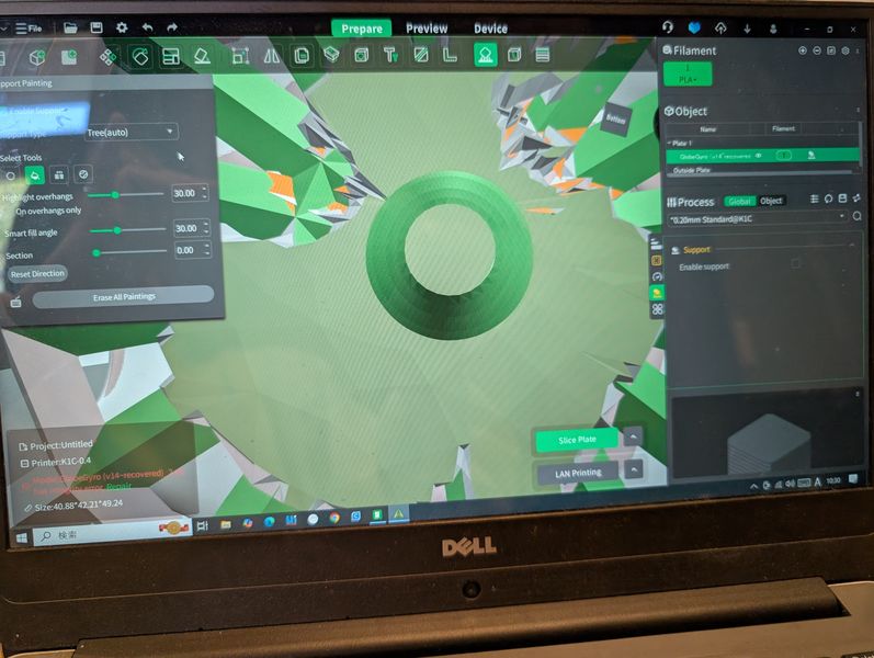
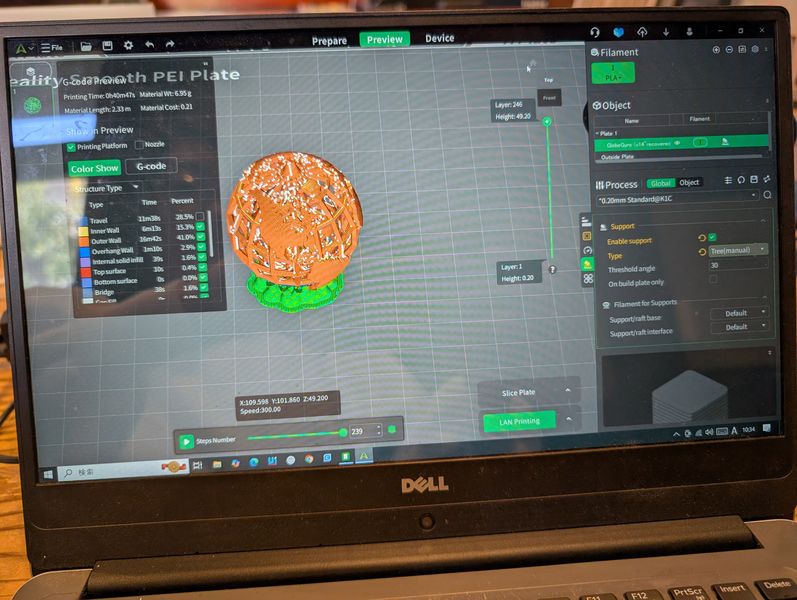
For globe part, I have to change
support
settings,
otherwise it might be impossible to take support parts.
Choose support menu from the
top
tool bar.
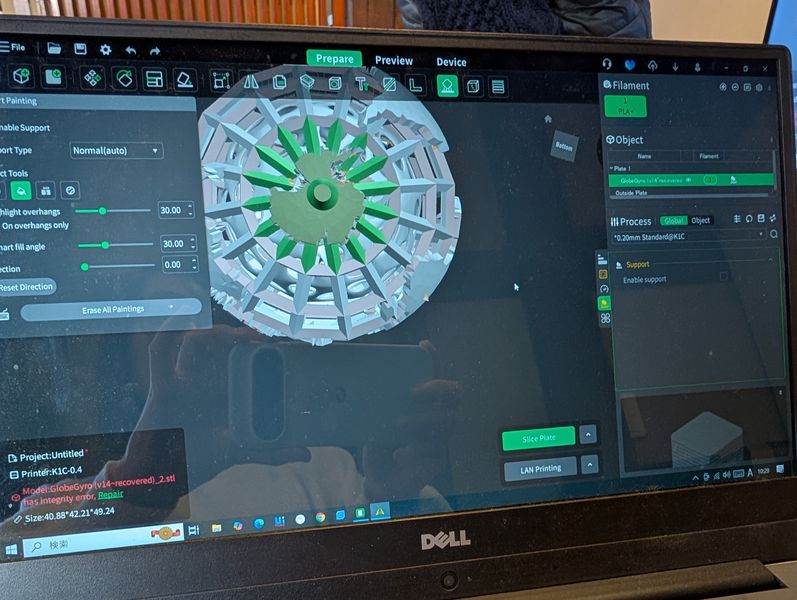
Use select tool, and select the face I need the support.
I’ve learned it is enough to
support only
the bottom part of the sphere.
I also used the “tree” support, which is easier to
take
away.
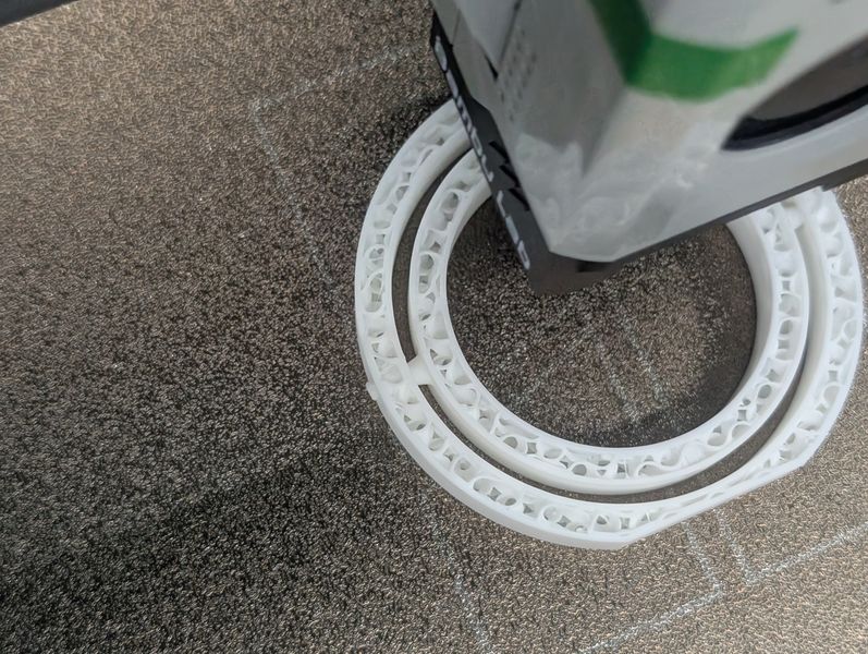
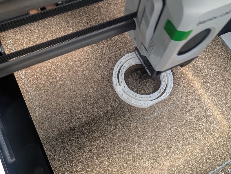
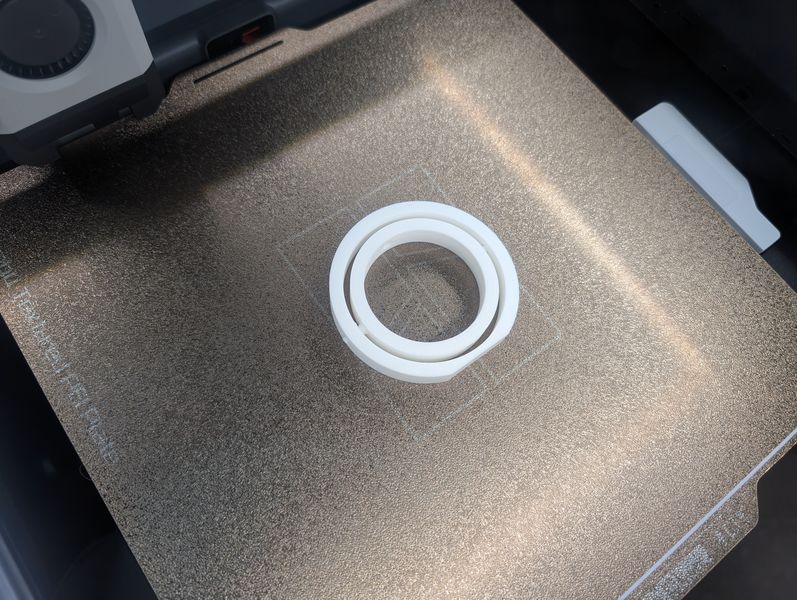
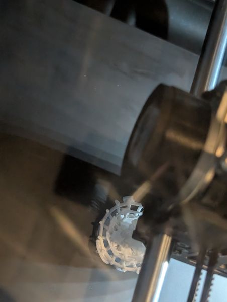
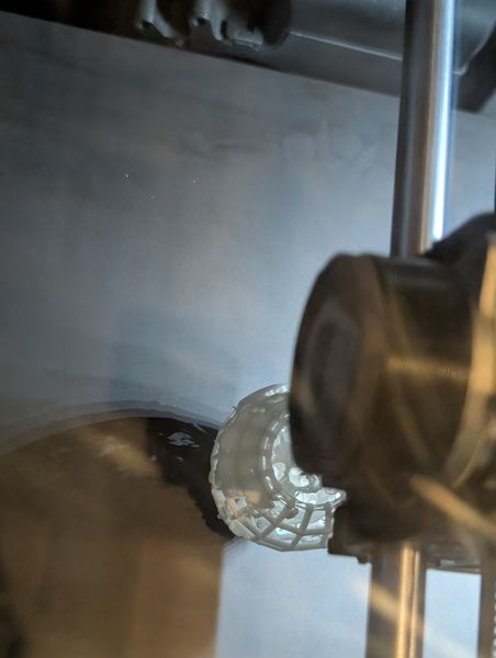
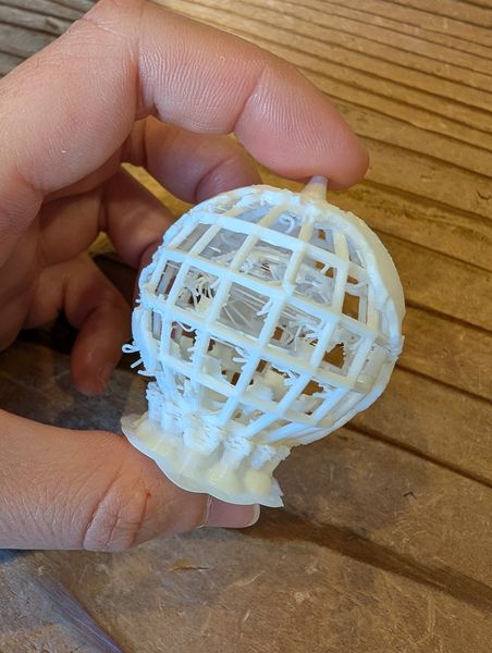
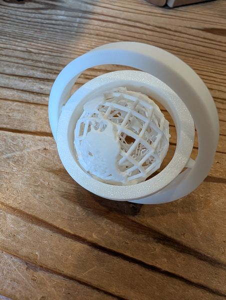
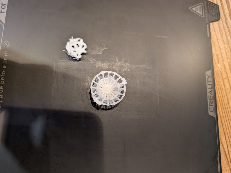
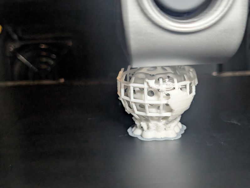
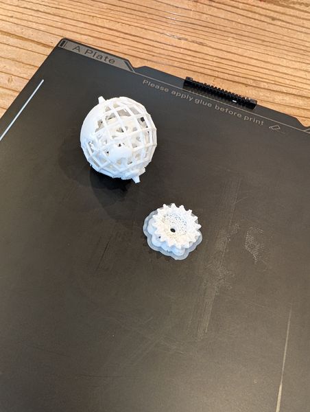
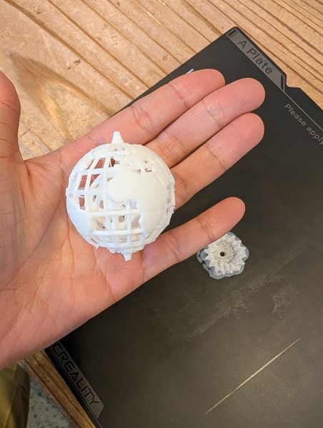
Ring parts: seems ok, and it moves!
Globe parts: Outside looks nice, but, Inside is spaghetti…
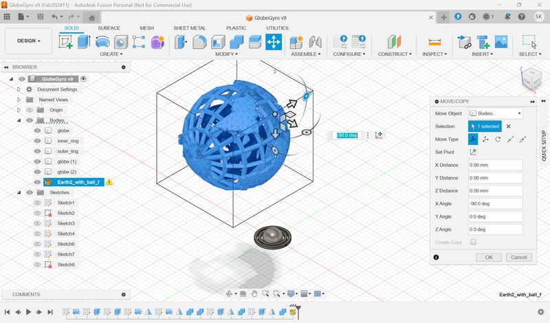
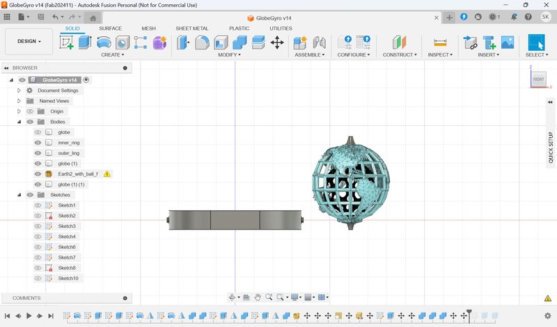
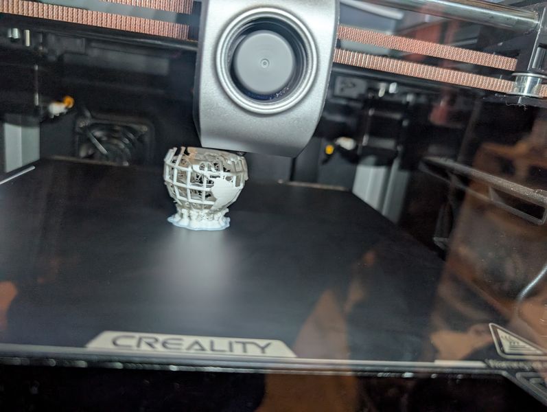
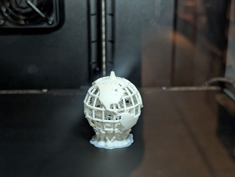
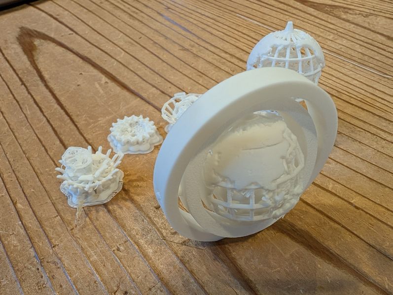
2nd and subsequent Print trials
Thickness 0.063mm→0.2mm
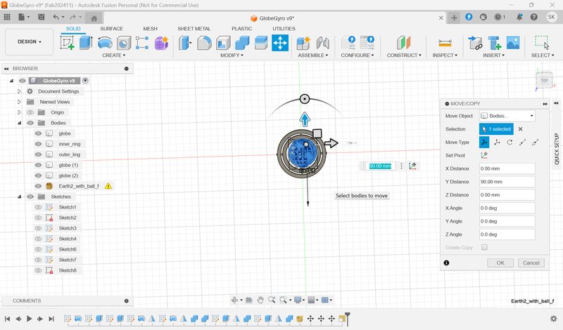
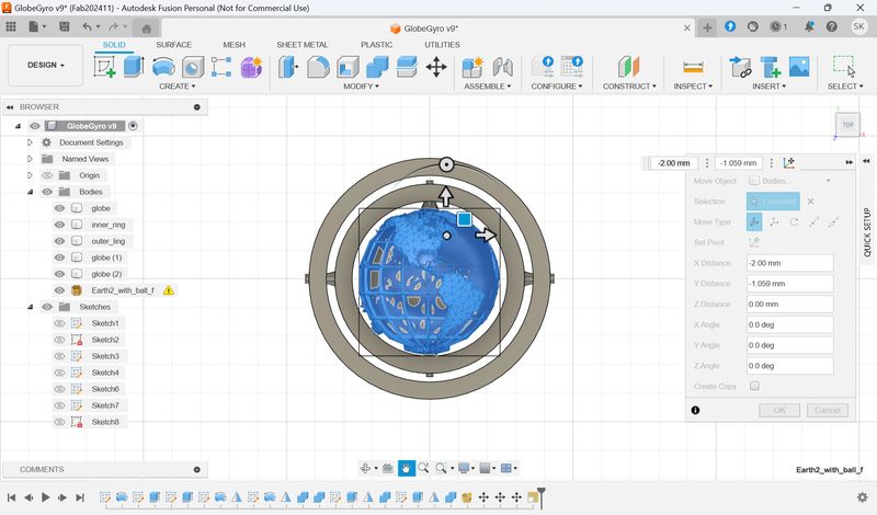
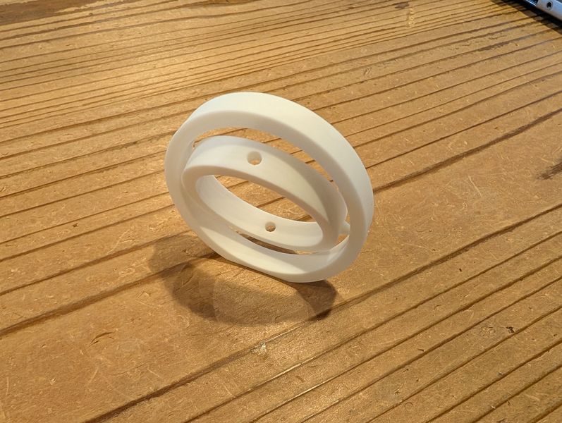
Move back to the original place to adjust junction parts.
I joint it to the ring parts.
The data is here.
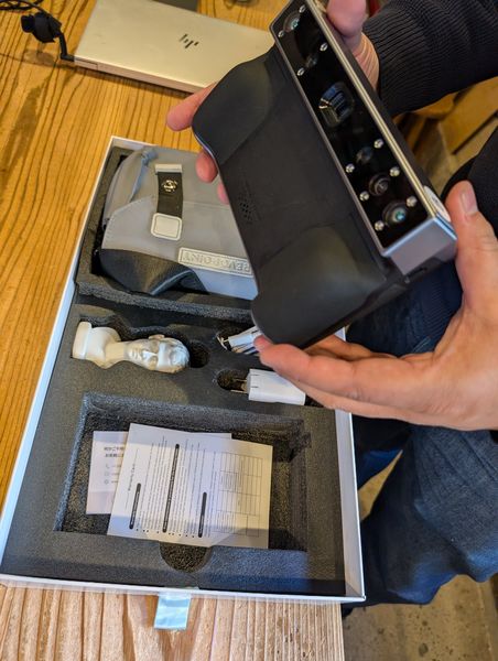
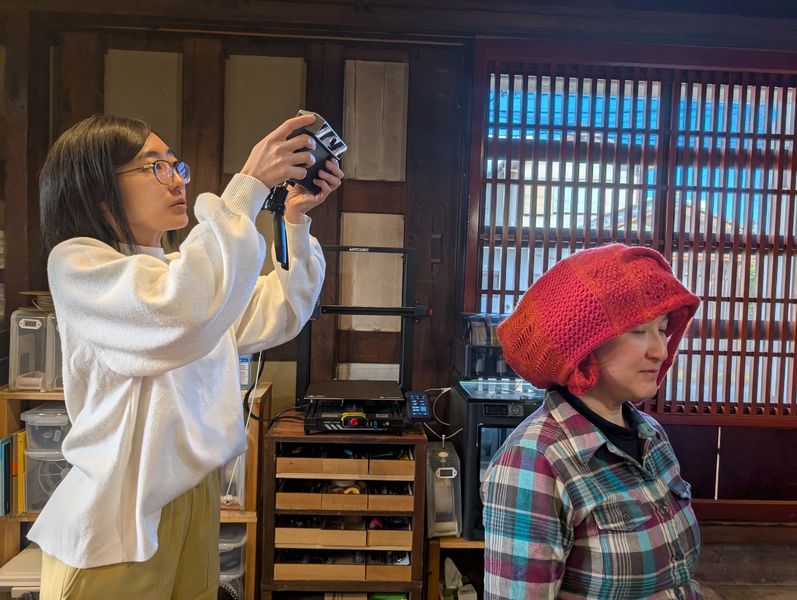
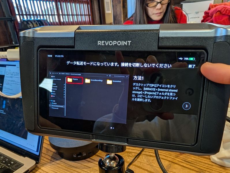
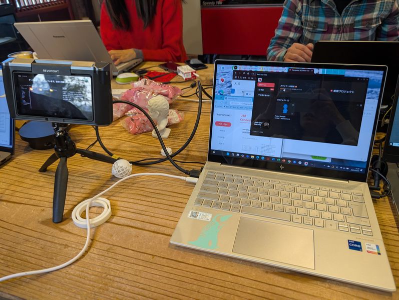
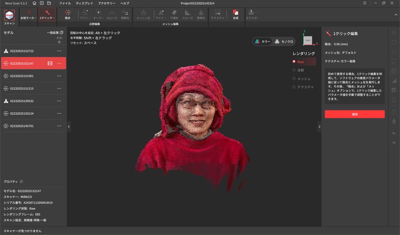
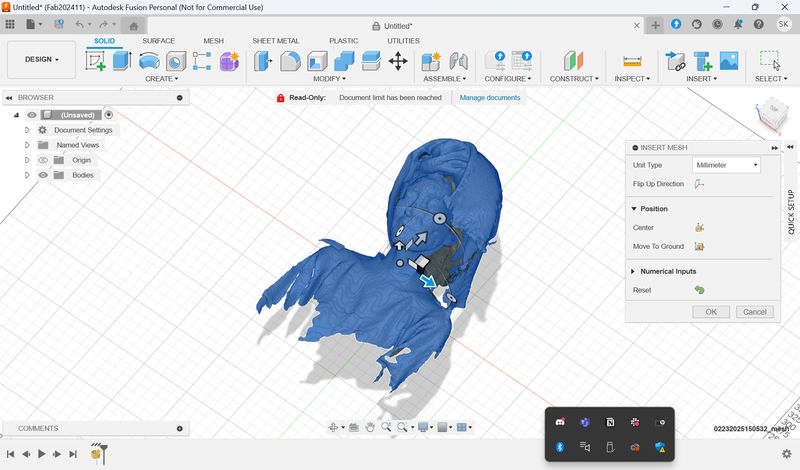
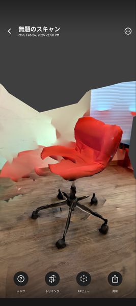
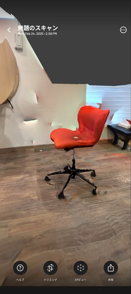
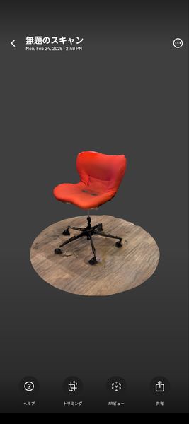
3D scan an object (and optionally print it)
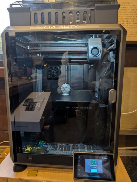
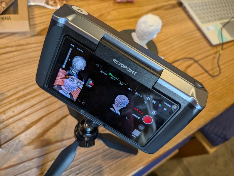
First, we take the sample figure as a trial.
Turn on, and press record button, and the scanning starts.
After scannnig, you can edit the model with “1-tap editing”function.
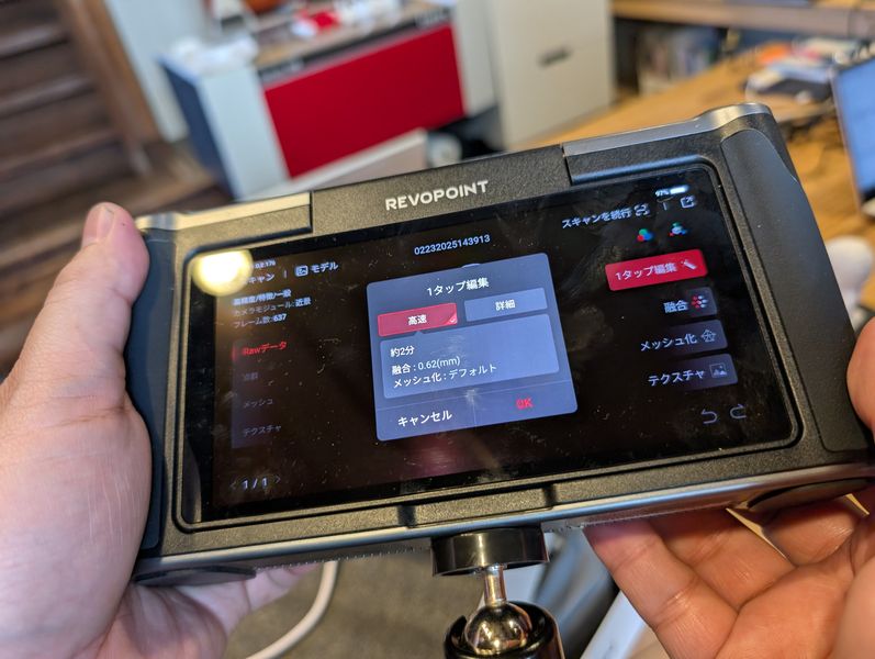
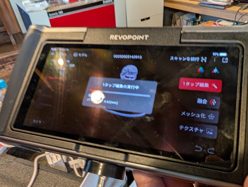

To do so, you have to install “Revo scan” software.
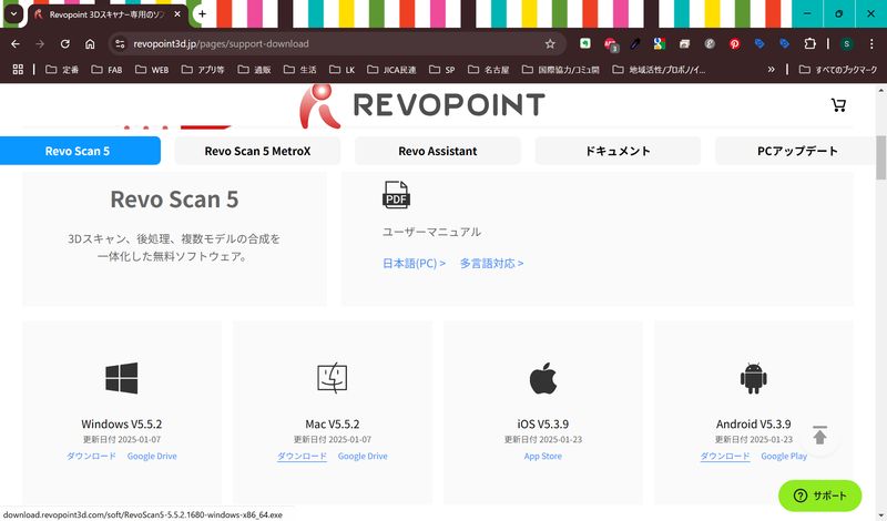
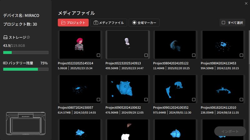

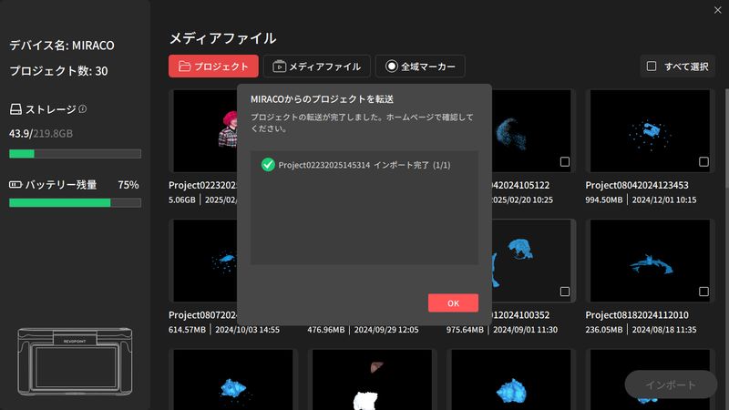
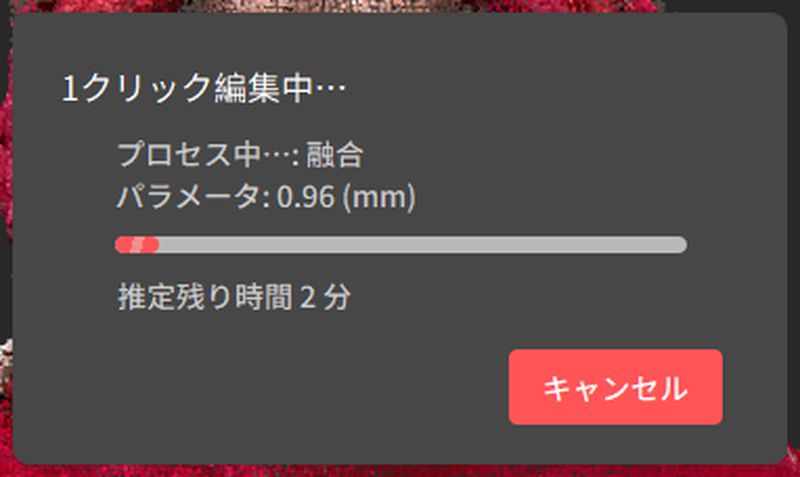
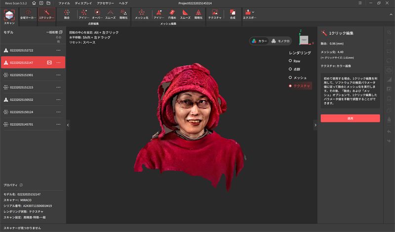
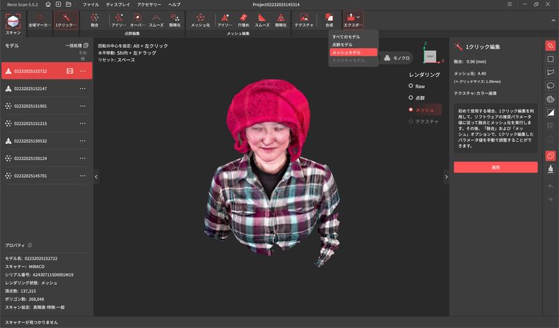
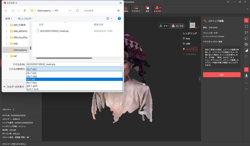
You can edit ply format with the software like: MeshLab(for free), Meshmixer(Autodesk), etc.
scaniverse
Outcomes
Data for 3D print
*"Globe with gyro" data made in Fusion is too much heavy(40MB) and impossible to put it in repo, so I upload the data separately.
- Gyro Part only(.f3d)
- Earth with mantle(.blend) (material)
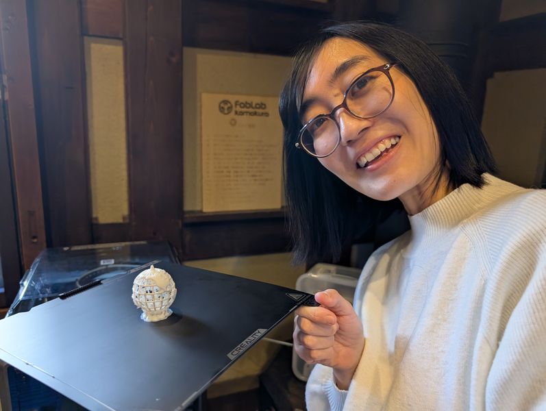
I could try some 3D printers, and 3D scanners. It was first time for me to print the
object
with complex shape. Also it was first time for me to use many kinds of 3D printers.
I was impressed that the new printers can print even intricate shapes quickly and clearly.
Also, I realized the importance of appropriate design suitable for characteristics of the
printers from retries.
*This page uses Google Translate to translate some sentences.