Final Project
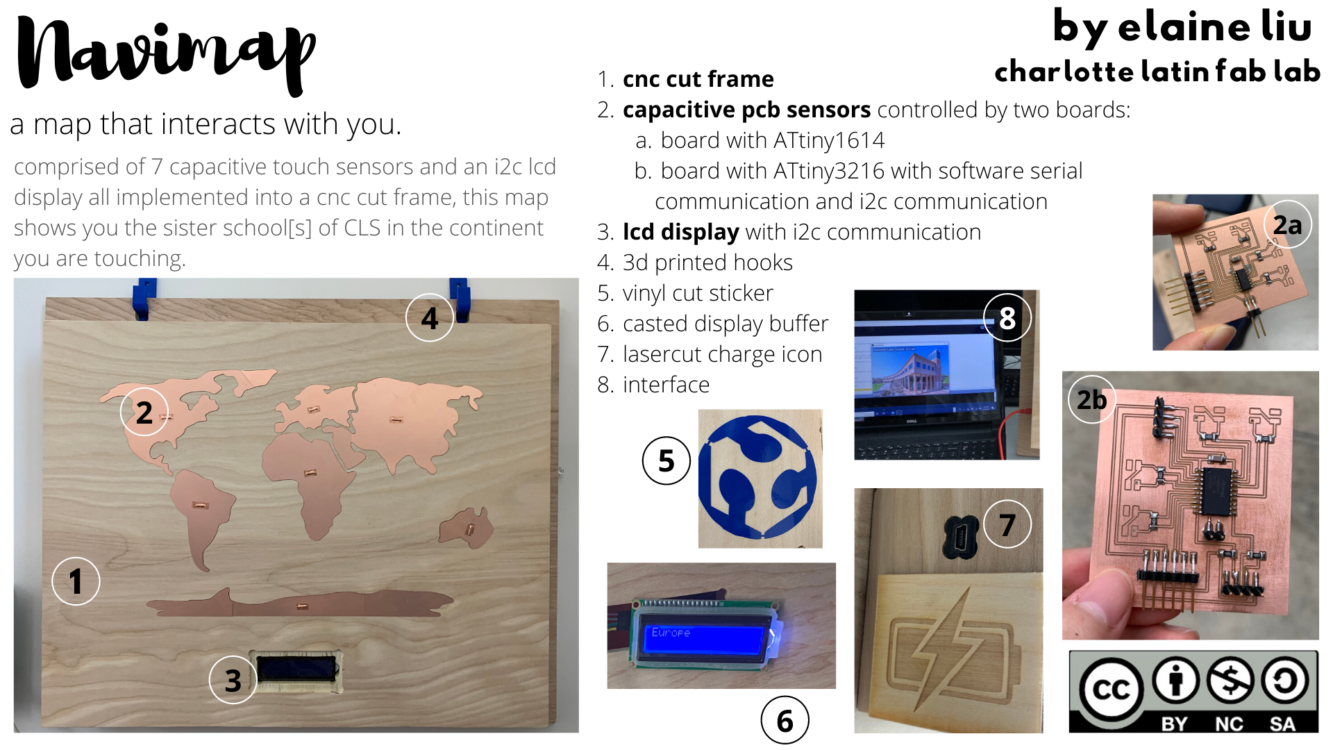
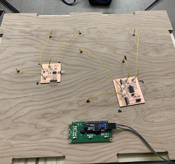
For my final project, I wanted to make an interactive, continent-naming touch map that allowed the user to look at pictures of our school’s sister schools across the globe. I used loading capacitive sensors to identify when a continent is pressed, an LCD display to output the continent name, and an interface using Processing to show pictures of the sister school when it’s continent is touched.
Video
Slide
Bill of Materials
Scroll right to see the full table.
License
As described in Week 13, I am using a Creative Commons License-NonCommercial-ShareAlike license. This license “lets others remix, adapt, and build upon your work non-commercially, as long as they credit you and license their new creations under the identical terms.” As I said in Week 13, I hope that others can build on my project without profit in mind and for their own use.

Research and Planning
For this project, I had to get a working understanding of capacitive sensors. I had worked on a smaller project that used capacitive sensors back in the first semester of school for a class, and it helped me get a little familiar with capacitive concepts. Here is the link to the project. However, there were problems with the project. I wanted to go back to researching more about how they worked, and how I could successfully implement more than one sensor into the project. I so far haven’t been able to find a capacitive sensor world map. However, there have been conceptually similar projects, like MIDI boards, or games that are similar to Operation Game, except with more outputs. I found this Exploding Kittens project that seemed functionally similar to mine. However, they used Adafruit capacitive touch products and electrical paint. I discovered that the BareConductive Touch Board does exactly what I need for my project, but I didn’t end up referencing it for electronics design.
I used the following resources/pieces of inspiration to help build a basic understanding of capacitive sensors:
- A Texas-Instruments Presentation
- The Microchip Capacitive Touch Sensor Design Guide
- An Instructables on Capacitive Sensing
I learned that capacitive sensors are very much unstable and requires careful grounding and calibration to use– I kept this in mind going forward.
Throughout the weeks, I tried to do as much as I could to build towards the final project. The following links show what I’ve done in each week:
- Test the input solo sensor board (week 9)
- Test the output LCD display board (week 11 and week 14)
- Test an interface (week 13)
At this point, I still had much to do, so I made a to-do list for myself:
- [x] choose continent map design and determine size (continents only; size 1.5ft x 1.2ft)
- [.5x] program and test test boards (threesensor board, foursensor board)
- [x] design continent pcb shapes
- [x] make frame design
- [x] design final boards
- [.5x] program and test final boards
- [x] design 3d printed parts if needed
- [x] mill out frame and continent shapes
- [x] assemble everything
- [x] calibrate everything
The following shows my work throughout the weeks to build towards my final project, along with the work I did before the presentation date.
Quick Summary
From my Project Development week (week 18/19) I made this table showing what parts of my project show what skill. You can click on any skill to navigate to the part of the project that used it.
| Skill | Project Implementation |
|---|---|
| CAD | Project design in Fusion360 / Inkscape |
| Vinyl Cutting | N/A, maybe accessories and a Latin sticker |
| Laser Cutting | Engraved Power Symbol |
| Electronics Production | Boards for sensors / communication |
| 3D Printing | Hooks |
| Electronics Design | Designing the electronics/boards for the project |
| CNC | Frame |
| Embedded Programming | Programs for the boards |
| Molding and Casting | frame for around the LCD display |
| Input Device | Capacative sensors (pcb copper map) |
| Output Device | LCD Display |
| Networking and Communication | Software serial communication between communication board and sensor boards, & I2C communication with LCD display |
| Interface and Application Programming | Processing interface to show images |
Project and Map Design
Old Designs
From week 1, I had decided that I was going to make a world map that played media corresponding to a region of the map upon being touched. The main sketch of the map from that week looked like this:
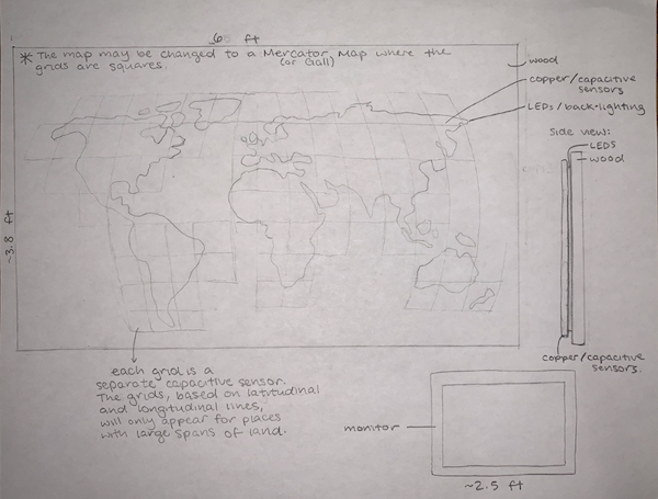
The map part of the project was originally planned to look like this– a Robinson projection with navigational lines. This was designed in Inkscape from week 2.

New Designs
However, after re-evaluating my project, I updated the sketch. This is what the new sketch looked like:
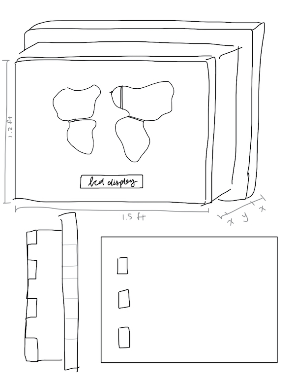
I decided that instead of using a grid system, I would just make each continent a sensor. This would allow me to have more stable capacitance as well, since each sensor would not be so small and closely gathered. I chose an image of a Robinson Projection map with outlines of continents only and went to Inkscape to design it. I traced the map using the Bezier Curves tool. This is what it looked like when I was done. I made sure that all the curves would be able to fit a 1/8” CNC bit.

CNC
Frame
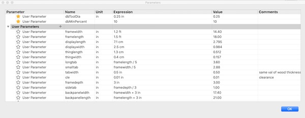
Before I could import the map sketch file into Fusion, I had to design the rest of the frame. I started with a sketch on paper, planning out any clearance values I needed.
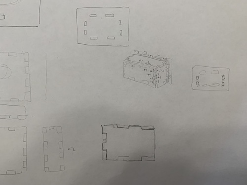
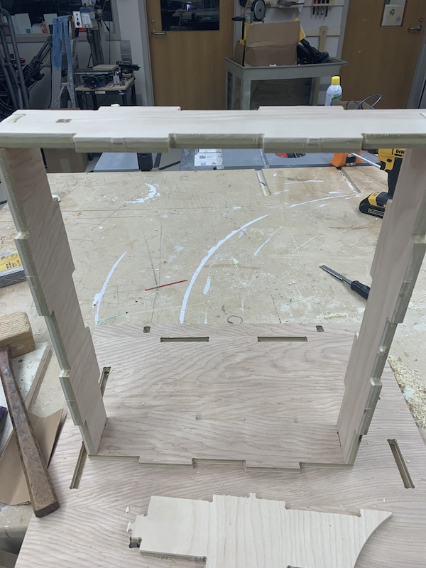
I then made each part. I made any parameters I might have needed then designed each part with those parameters. I started with a sketch then extruded them. This is what the tabbed sides, front, and top looked like before dogboning everything:
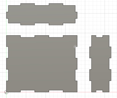
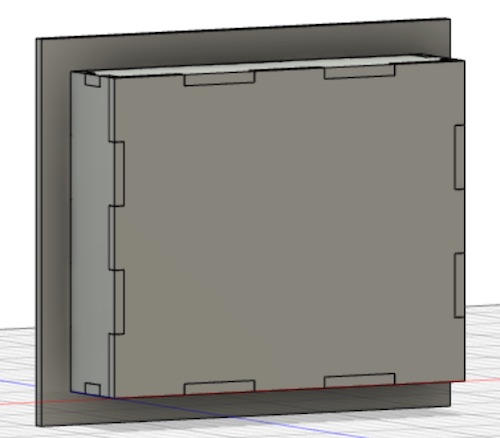
I made a copy of both the side piece and top piece, and I used the Dogbone extension I found back in week 7 to dogbone all the faces of the pieces. After I made the back piece, I used the Align tool to simulate what the project would look like.
It was then time to import the svg file of the map onto the front piece. I imported the file and made an extrude cut of 1/16” into the front piece of wood. For the display, I made an extrude cut the size of the display, and a cut of .125” into the wood around it.
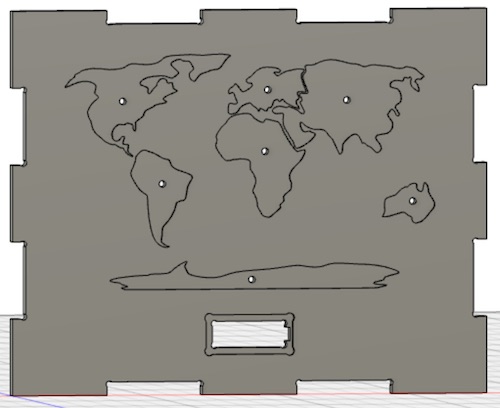
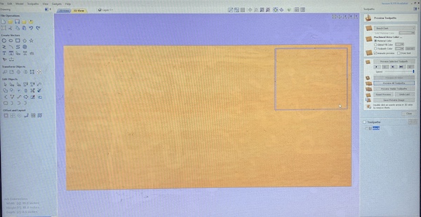
To make sure that all the curves would be able to fit a 1/8” bit, I simulated toolpaths–I didn’t want the engraved part of the frame to not fit the actual sensors. I started by making a new setup just for the front of the frame. Luckily, it seemed like everything worked out well!

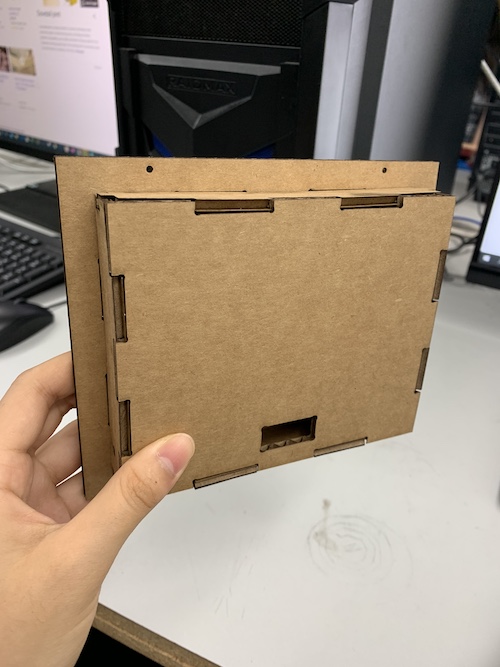
Before I milled it out, I wanted to prototype it in cardboard. I exported all the files as a DXF file, opened it in CorelDraw, and lasercut it in cardboard. This is how it turned out!
I then realized I would be making 3D hooks and needed a hole to hook them onto the back of the frame. I added two rectangular holes on the top.
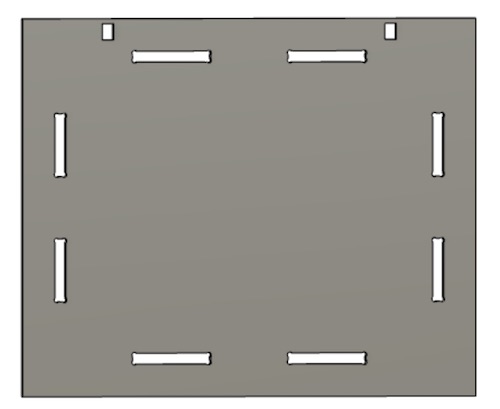
I made toolpaths for all the frame parts except for the front piece. Following the same instructions I did for Week 7, I made Pocket cuts for the holes on the back frame and 2D contour cuts to outline them. I used tabs and placed them along the pieces.
After Post Processing them, I followed the CNC workflow from Week 7 and milled it out. Unfortunately, I had forgotten to switch the X and Y axis so my toolpaths hit into a previously milled circle. This caused one of my top pieces to not mill out properly.
So, I quickly created a new toolpath in a new setup for one top piece. I couldn’t add an offset to just the right side, so I added it to the outside of the model. I added 30 inches. This caused the piece to mill out farther than expected– to fix this problem next time, I would made the offset smaller. To avoid the problem altogether, I would switch the axes on my setup.

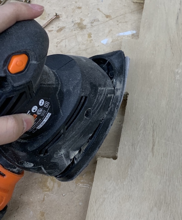
Before assembling the pieces, I post processed them by using a handheld sander.
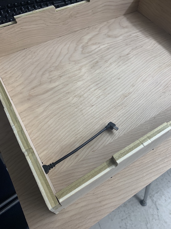
To assemble the pieces, I first assembled the side of the frame, the malleted the pieces onto the back piece. I also fit the mini usb extension cord into the side hole. It fit!
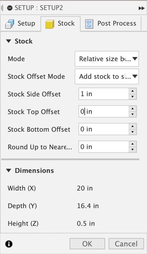
I also got the stock ready for the top piece. I used Aspire to make a rectangular toolpath with drill holes in each corner. The dimensions of the rectangle are each 2 inches larger than the dimensions of the stock of my Fusion setup for the front piece. On Aspire, I drew a rectangle, and on each corner 1 inch into the rectangle on both sides I drew a circle with a diameter of 0.25”. I then made toolpaths for the design. For the drilling toolpaths, I set the cut depth to 0.5”. For the 2D Profile Toolpath (similar to Fusion’s 2D Contour), I set the cut depth to 0.5”, edited the passes to 3, set Machine Vectors to Outside/Right, and added tabs of length 0.25” and thickness 0.125”.
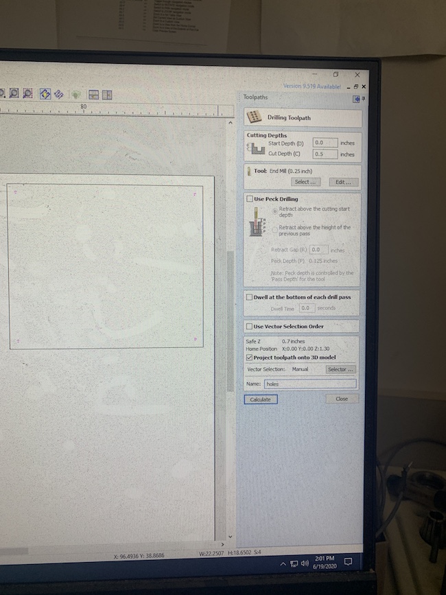
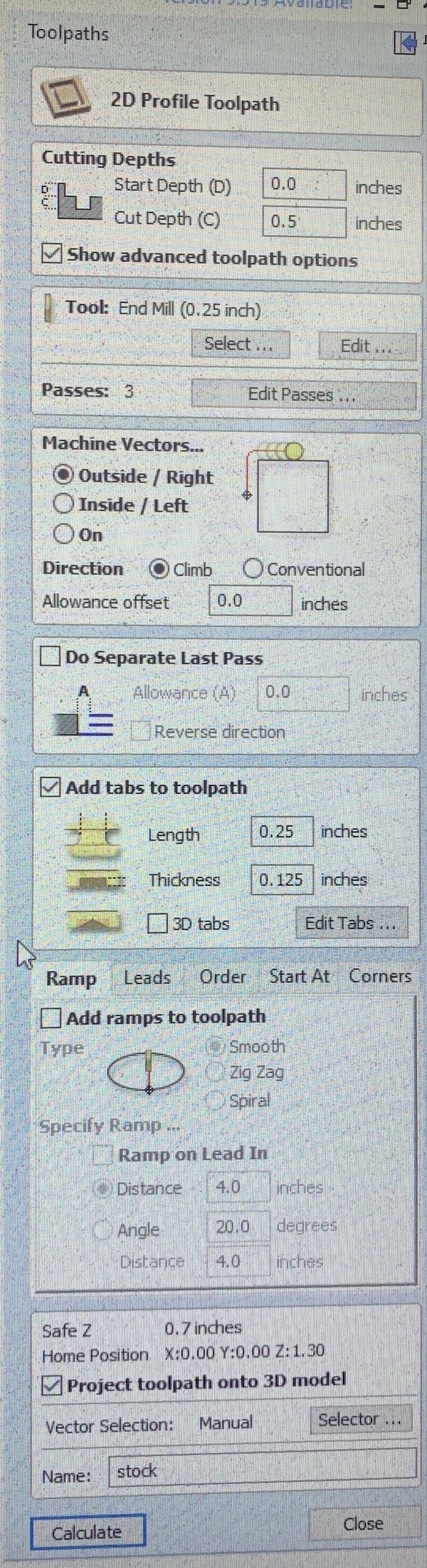
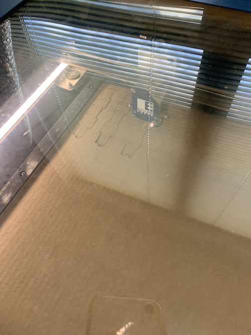
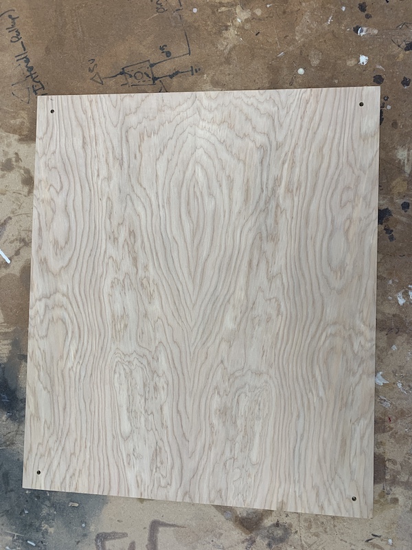
This is how the stock came out:
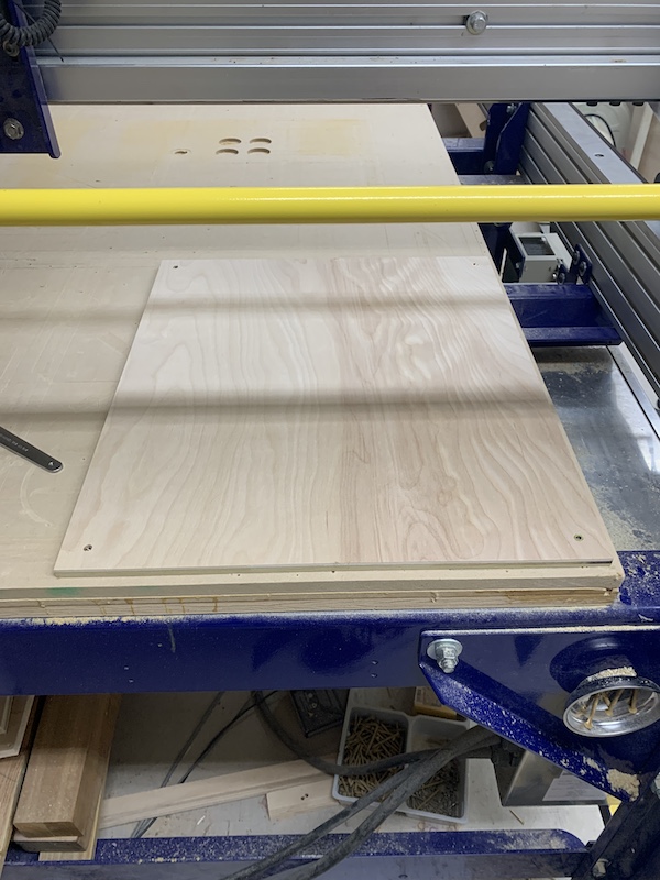
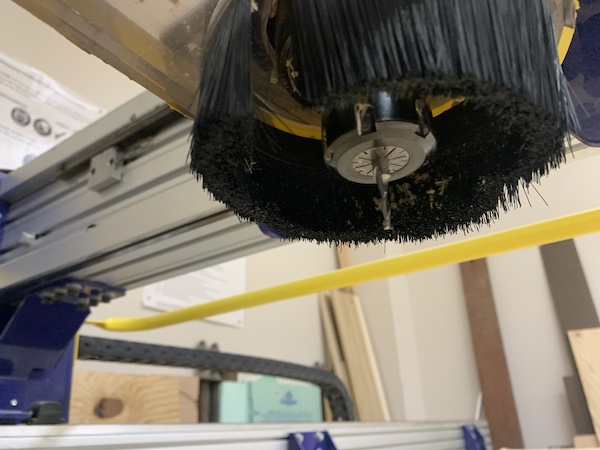
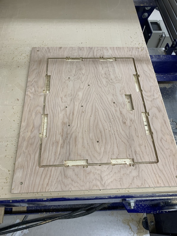
It was then time to mill the stock. I lined up the stock on the bed, making sure I properly laid it on the table in relation to my setup’s x and y axes. I carefully screwed the stock into place with its corner on the origin. I switched the bit to a 1/8” bit for the map.sbp file cut, then I milled it out.
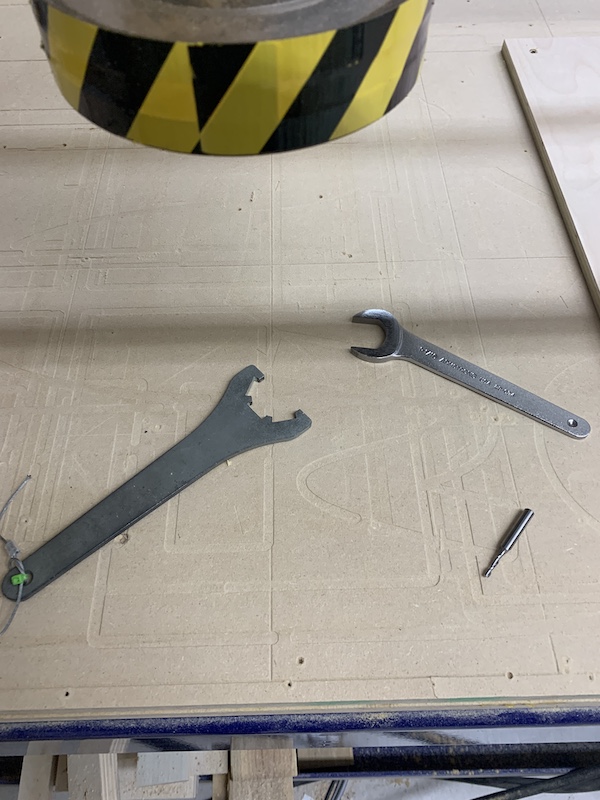
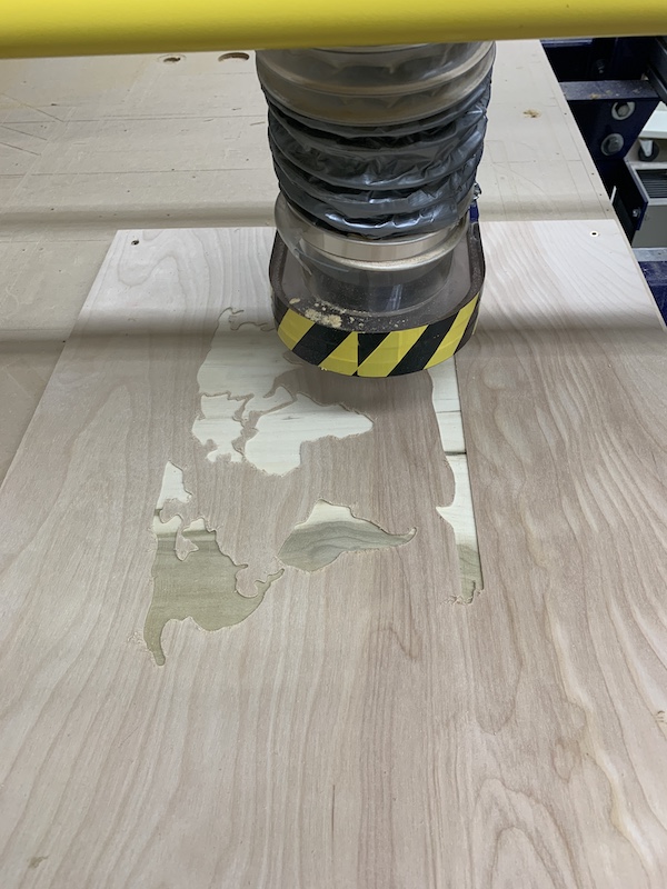
I then changed the bit back to the 1/4” bit. I drilled out the holes and the display parts.
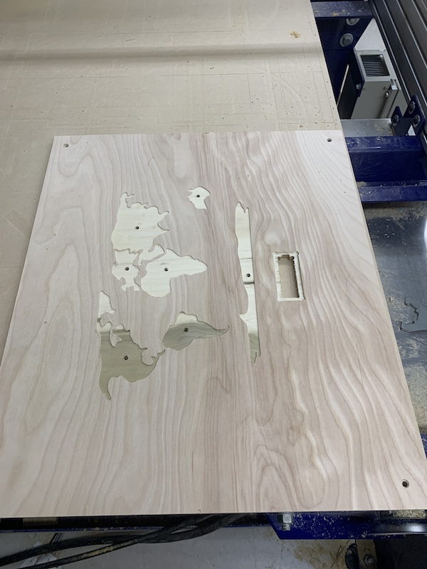
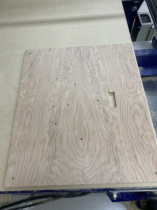
Afterwards, I removed the screws, flipped the stock over, carefully lined it up against the origin, and rescrewed it in. I then milled out the tabs and the 2D Contour cut.
Sensors
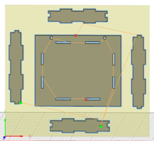
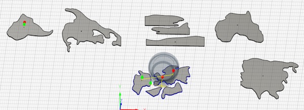
I used the same svg file of the map to make the toolpaths for the sensors in Fusion. I made an offset of 0.01” around each continent so that they would fit snug in the frame. I also split up some continents that would not fit on one sheet of FR1. I made the holes for each continent smaller as well so that I could fit a wire through. I then worked on the toolpaths for them. I made one 2D Contour and one Boring path for each setup.
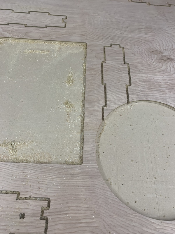
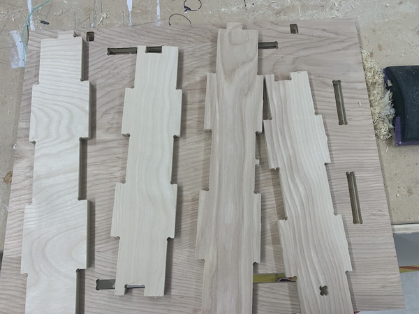
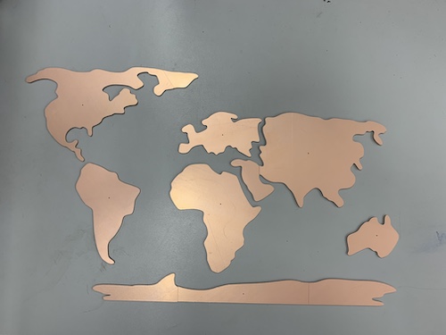
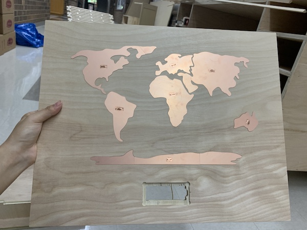
I Post Processed all the toolpaths separately, imported them into Bantam, and milled them out setup by setup. I sanded the edges of the continent parts using P220 sandpaper and they came out nicely!
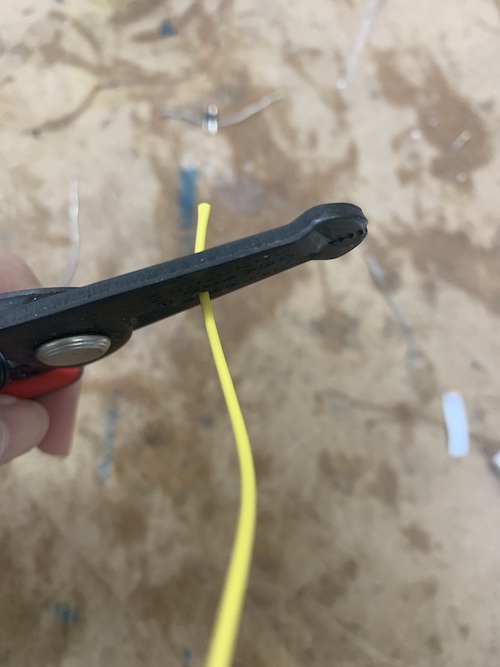
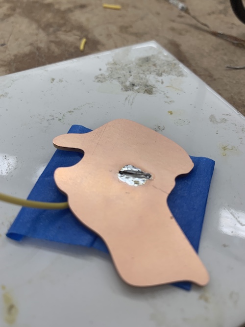
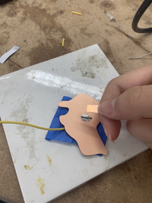
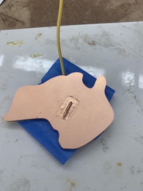
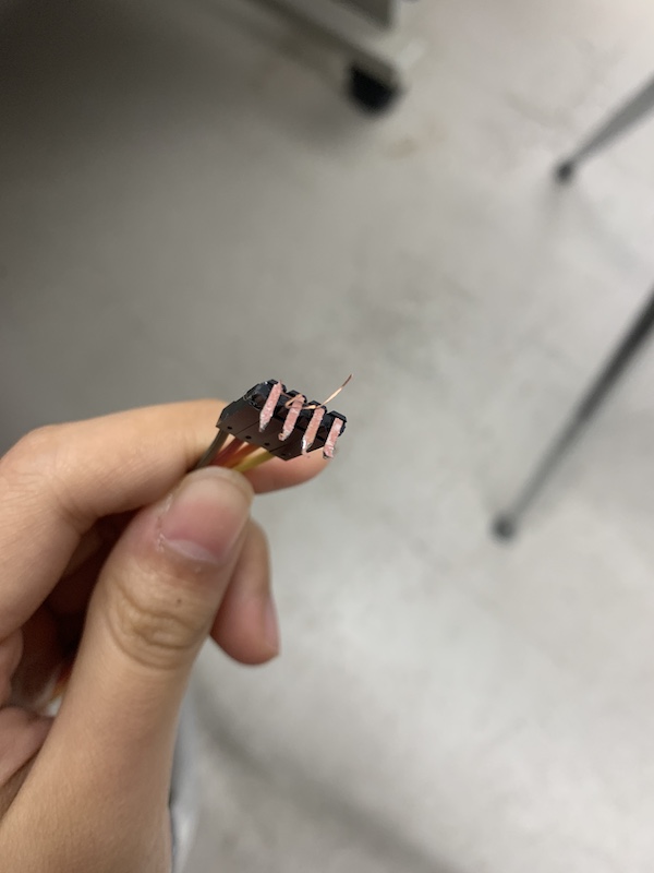
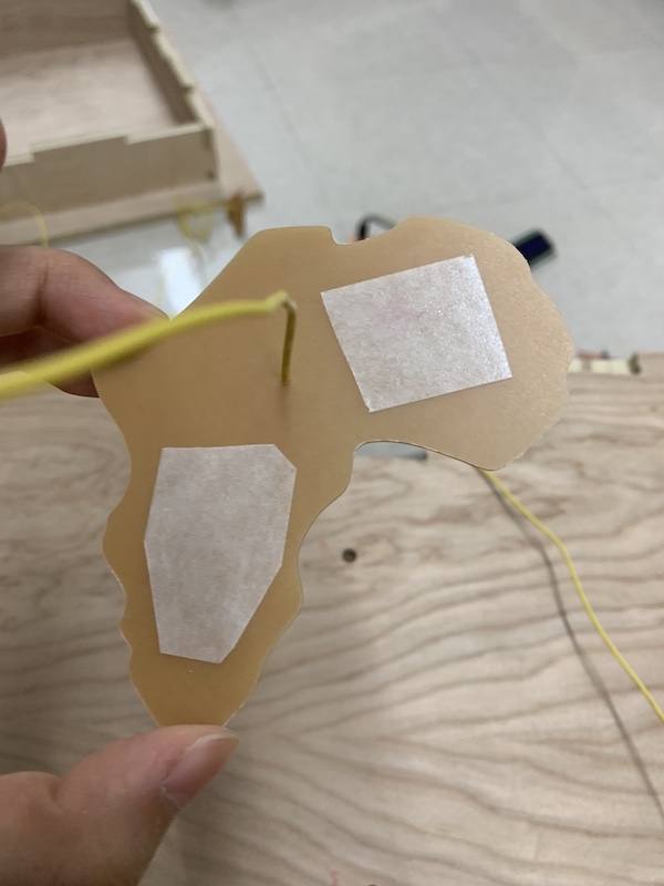
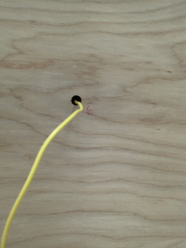
To prepare for implementing them into my final project, I stuck the wires into the sensors. I took a strip of wire, stripped slightly less than one centimeter of it, stuck it into the hole of the sensor, bent it, and soldered it on. Afterwards, I used copper tape to make it look more subtle.
This is the Fusion file I used for the Shopbot and Othermill parts:
Hooks
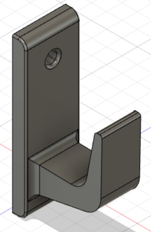
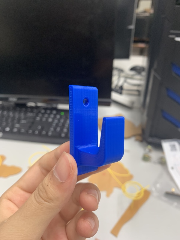
I wanted to implement 3D printing as well, and I needed hooks anyways. So, I designed 3M type hooks that I could tape on the back. This was my reference that I found on Thingiverse by @andrewar. I quickly designed something that would fit the size of the holes on the back of the frame.
I then saved the body as an .stl file and opened it in Cura. As my Fab classmate Harri was about to print something out, I squeezed two hooks onto the 3D printer bed. This is how they turned out after I took tweezers and removed the support!
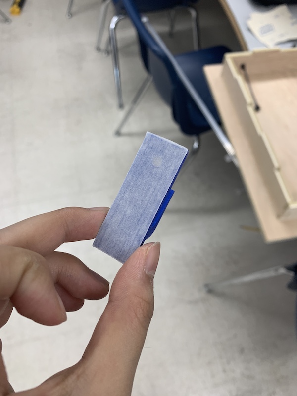
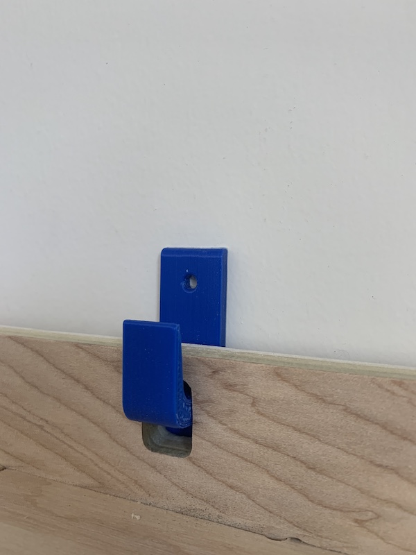
I then stuck the hook on a piece of nitto tape. I used an X-Acto knife to cut the excess tape around the hook off of it. I took off the backing of the nitto tape, and I had a sticky hook! I hooked the frame onto the hooks, stuck it to a wall, and it stayed! This is what it looked like:
LCD Display Buffer
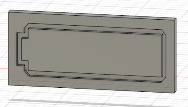
Since I needed to insert the LCD display into the frame, I needed a small layer of soft material to flatten the contact surface out between the display and the wood. There were a row of soldered pins, and I wanted to be able to overlook that when positioning my LCD display. So, I designed a 3D printed mold that would allow me to use a soft caste.
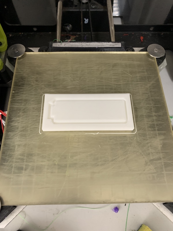
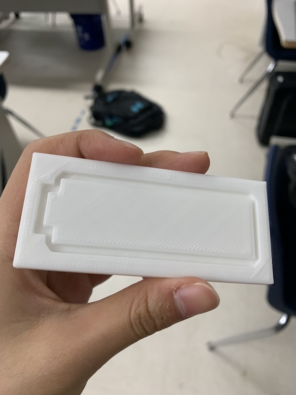
I then exported the body as an .stl file and imported it into Cura. I then 3D printed the mold.
This is how it turned out:
Then, I used ECOFLEX 00-35 FAST parts A and B since I was familiar with it from week 15. I mixed and poured equal parts of Part A and B into a cup, stirred for around 15 seconds vigorously, then tried to carefully pour it into the mold. The pour was alright, but then I tried to scrape off excess liquid from the top. This proved to be a semi-messy decision, as it caused the ECOFLEX to go all over the mold.
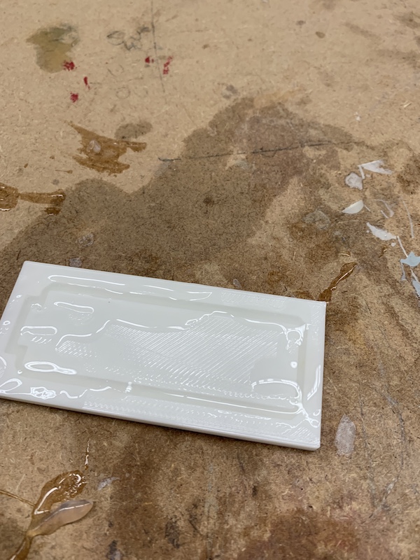
I waited for around 8 minutes, then used an X-Acto knife to cut around the edges. I carefully took the cast off, and this is what I got.
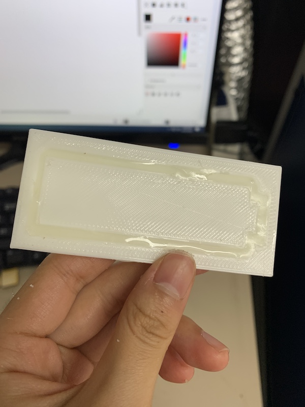
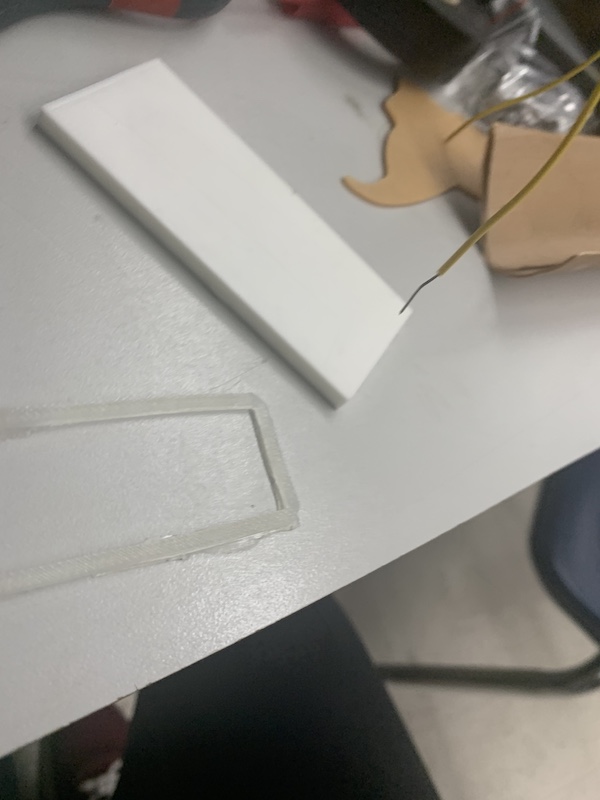
I had to clean up the edges a little more afterwards. The cast was a little flimsier than I thought it would be, but it serves its purpose of stopping the front of the LCD display well.
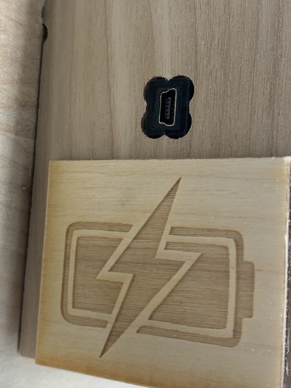
Charging symbol
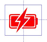
I wanted to engrave a small charging symbol for the charging port on the side of my project. I found this image of a charging symbol and liked it a lot.

I copy and pasted it into CorelDraw, then Bitmaps traced it by going to Bitmaps > Outline Trace > Line Art. I set the colors to Black and White, and got this.

I then deleted the shutterstock words, made it the red, and added a blue rectangle around it. I used Guidelines to help me center everything.
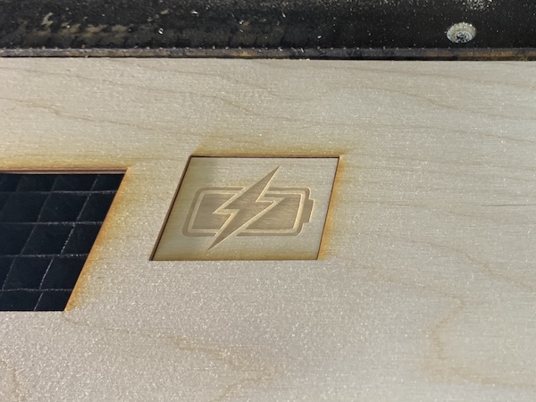
After grouping everything, I sized it down a little until the width of it was approximately 2.3 inches. I printed it with 300 DPI as the resolution, made the blue color settings: 2s, 100p, 10f, and the red color settings: 50s, 100p. I hit go, and let the laser cut work its magic.
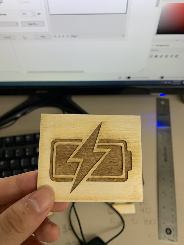
It turned out alright, but I wanted a smaller and lighter engraving. So I sized everything down so that the width was 2 inches, increased the engraving speed to 40s, and hit go. This time, it was more of what I had wanted.
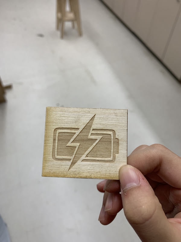
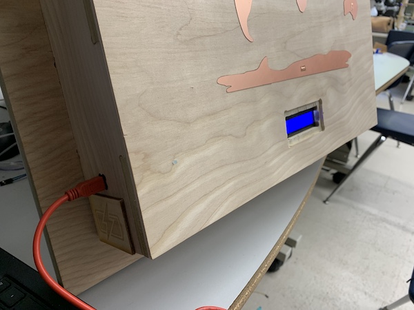
I used Nitto tape to attach the engraving to the side of the frame. This is what it looked like.
Vinyl Sticker
Since I wanted my project to be reminiscent of the lab, I vinyl cut a Fab Lab logo sticker. I used the CLS Fab Lab logo here as reference.

I imported the photo into Corel Draw, then Bitmaps Traced it by going to Bitmaps > Outline Trace > Line Art. I then unfilled the design and made any outlines hairline lines. I also used the 2 Point line tool to add two lines between each separate part of the logo and used the Virtual Segment Delete tool to delete the perpendicular lines in between. This connected each previously separate parts of the logo.

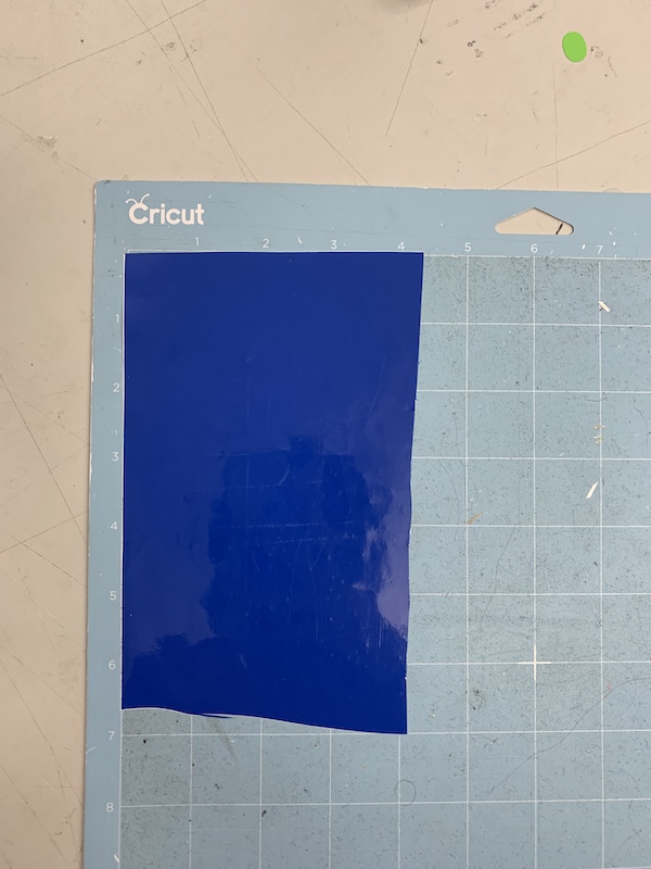
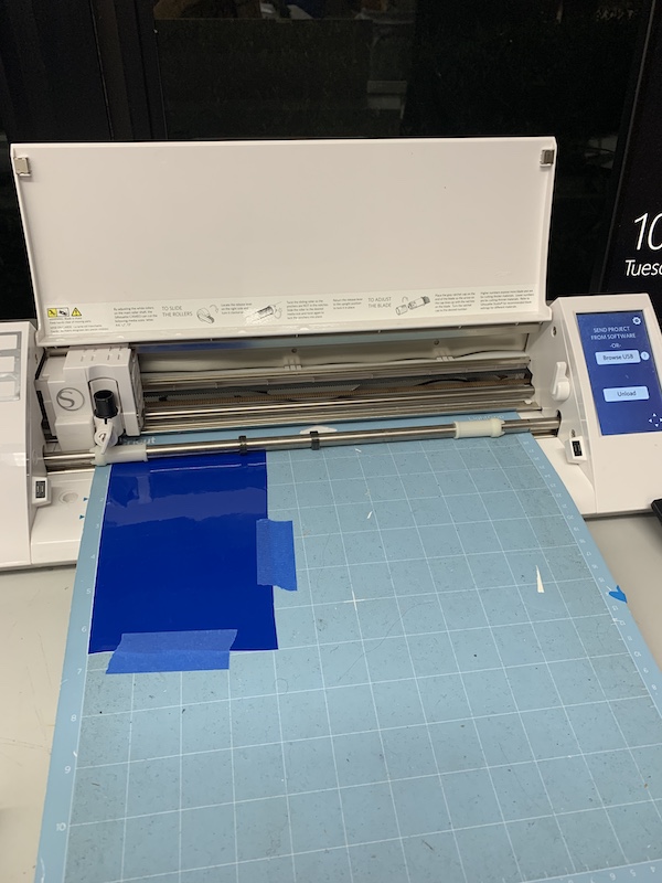
I exported the file as an .svg file and imported into Silhouette. I selected and grouped everything and resized it so that its width was approximately 2.25”. I then hit Send, selected my material as Vinyl, Glossy and hit send. Meanwhile, I stuck on a piece of blue vinyl onto the “bed” sheet of the vinyl cutter. Because the sheet was no longer sticky, I had to use some painters tape to hold down the edges. I loaded the sheet onto the vinyl cutter then hit start.
After it was cut, I unloaded the sheet and took the painters tape and vinyl off. Using tweezers, I removed the inner part of the sticker and the outside part. I then stuck the vinyl back of the bed sheet, made sure it was flat, and stuck transfer tape to the sticker, using a flat edge to flatten everything out. I then took an X-Acto knife and cut around the sticker.

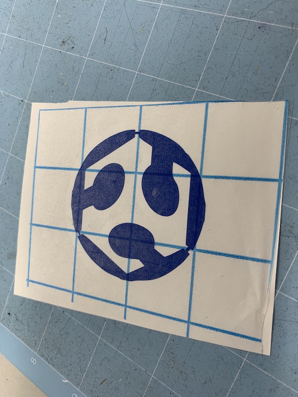
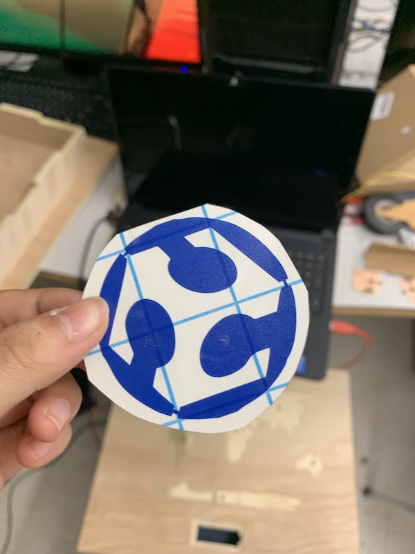
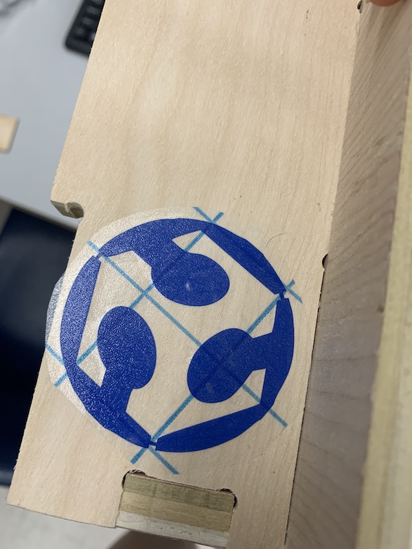
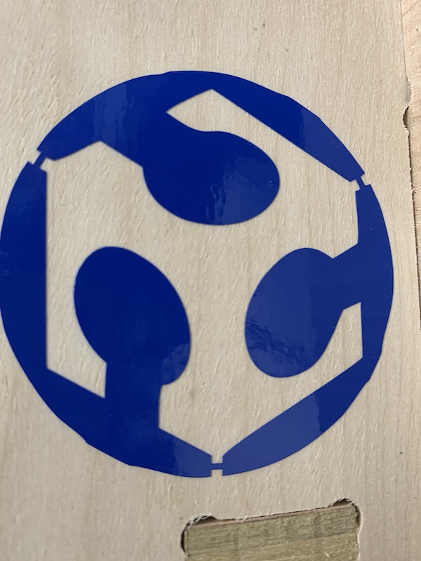
I then lined up where I wanted the sticker, peeled the transfer tape (with the sticker) from the backing. I placed the sticker down and pressed hard. I used a flat edge to smooth everything out. I then peeled up the transfer tape. This was my sticker!
Electronics
Trial boards
Individual charge pins
For the electronics of my project, I originally decided, thanks to the advice and assistance of Dr. Harris, one of our Fab instructors, that I would use three boards: two sensor/targets boards (one with three sensors and another with four) and one communication board with the LCD display with I2C communcation connections and rx/tx/ground/power connections to communicate with the two other target boards. Before I got to the communication board, I first wanted to test which type of sensor board would be best: one where each sensor has its own charge pin or one where each sensor shares a charge pin with all the others. You can see my proof of concept for capacitive sensing back in my Week 9 input week work.
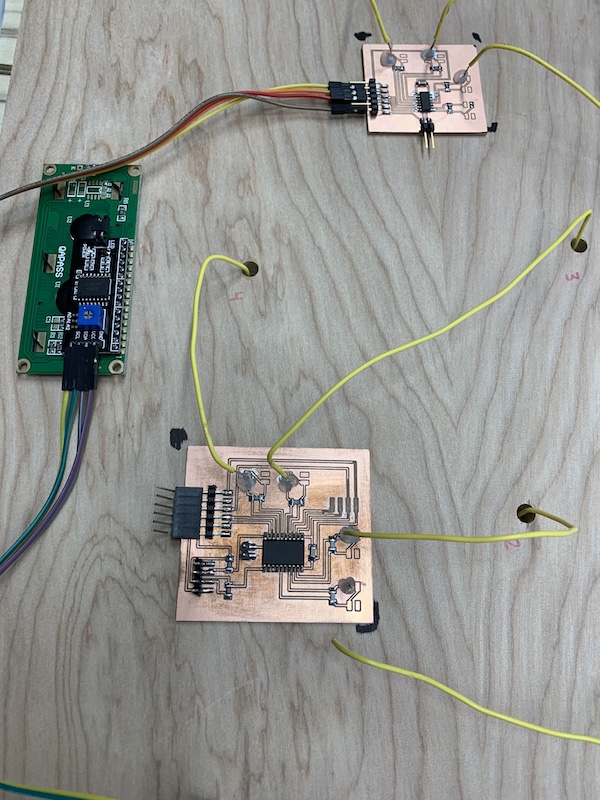
I tested my individual charge pin sensor boards that I had soldered back in week 13. After I soldered on some wires onto the sensors, I wired everything together.
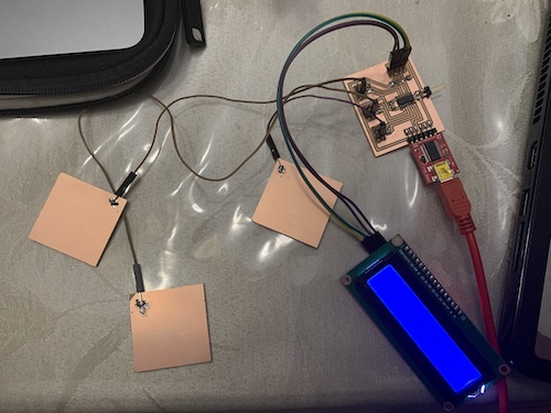
Then, I referenced my code from the input week (week 9) to create a larger code that would first test all three sensors.
Then, I tried to implement the display. I referenced my code from the networking and communications week (week 14) and this is the code I came up with:
#include <util/delay.h>

#define CHARGEPIN1 2
#define READPIN1 3
#define CHARGEPIN2 0
#define READPIN2 1
#define CHARGEPIN3 8
#define READPIN3 9
#define settleDelay 100
#define chargeDelay 1

#include <Wire.h>
#include <LiquidCrystal_I2C.h>

// Set the LCD address to 0x27 for a 16 chars and 2 line display
LiquidCrystal_I2C lcd(0x27, 16, 2);

int reading1;
int reading2;
int reading3;

void setup() {
  // put your setup code here, to run once:
  Serial.begin(115200);
  pinMode(CHARGEPIN1, OUTPUT);
  digitalWrite(CHARGEPIN1, LOW);
  pinMode(CHARGEPIN2, OUTPUT);
  digitalWrite(CHARGEPIN2, LOW);
  pinMode(CHARGEPIN3, OUTPUT);
  digitalWrite(CHARGEPIN3, LOW);
  lcd.begin();
  // Turn on the blacklight and print a message.
  lcd.backlight();
}

void loop() {
  //settle, charge, and wait
  delay(settleDelay);
  digitalWrite(CHARGEPIN1, HIGH);
  digitalWrite(CHARGEPIN2, HIGH);
  digitalWrite(CHARGEPIN3, HIGH);
  delay(chargeDelay);
  reading1 = analogRead(READPIN1);
  reading2 = analogRead(READPIN2);
  reading3 = analogRead(READPIN3);
  //send result
  Serial.println(reading1);
  Serial.println(reading2);
  Serial.println(reading3);
  Serial.println(" ");
  //implementing the display
  if (reading1 < 1021){
    lcd.clear();
    lcd.print("one");
    delay(100);
  }
  else if (reading2 < 1021){
    lcd.clear();
    lcd.print("two");
    delay(100);
  }
  else if (reading3 < 1021){
    lcd.clear();
    lcd.print("three");
    delay(100);
  }
}
It worked well!
Shared charge pin
I also tried to test out the shared sensor board. After wiring everything together, I kept getting errors when I programmed it. I tried reprogramming an old board to make sure there wasn’t an issue with the programmer, and it was fine. So, I knew there was something up with my board. I looked at my .brd file and realized I forgot to make a connection between the the power from the microcontroller to the 6x1 pin. So, I went back and edited it.
I still wrote the code for this board–it wasn’t too difficult to change some variables and declare some new ones.
#include <util/delay.h>

#define CHARGEPIN 8
#define READPIN1 1
#define READPIN2 0
#define READPIN3 10
#define READPIN4 9
#define settleDelay 100
#define chargeDelay 1

#include <Wire.h>
#include <LiquidCrystal_I2C.h>

// Set the LCD address to 0x27 for a 16 chars and 2 line display
LiquidCrystal_I2C lcd(0x27, 16, 2);

int reading1;
int reading2;
int reading3;
int reading4;

void setup() {
  // put your setup code here, to run once:
  Serial.begin(115200);
  pinMode(CHARGEPIN, OUTPUT);
  digitalWrite(CHARGEPIN, LOW);
  lcd.begin();
  // Turn on the blacklight and print a message.
  lcd.backlight();
}

void loop() {
  //settle, charge, and wait
  delay(settleDelay);
  digitalWrite(CHARGEPIN, HIGH);
  delay(chargeDelay);
  reading1 = analogRead(READPIN1);
  reading2 = analogRead(READPIN2);
  reading3 = analogRead(READPIN3);
  reading4 = analogRead(READPIN4);
  //send result
  Serial.println(reading1);
  Serial.println(reading2);
  Serial.println(reading3);
  Serial.println(reading4);
  Serial.println(" ");
  if (reading1 < 1021){
    lcd.clear();
    lcd.print("one");
    delay(100);
  }
  else if (reading2 < 1021){
    lcd.clear();
    lcd.print("two");
    delay(100);
  }
  else if (reading3 < 1021){
    lcd.clear();
    lcd.print("three");
    delay(100);
  }
  else if (reading4 < 1021){
    lcd.clear();
    lcd.print("four");
    delay(100);
  }
}
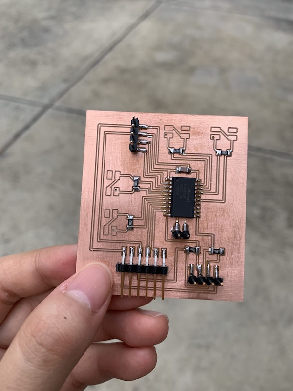
After I milled the new board and soldered everything together, this is what I got.
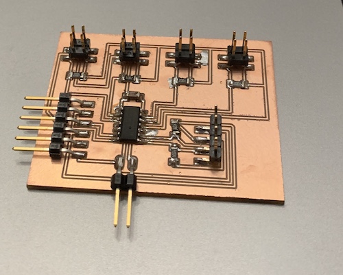
I coded it with the code from above, and found that the second sensor was not very sensitive whereas the first and third were. So, I wanted to use the type of board where each sensor has its own charge pin.
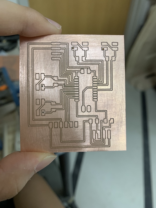
Final Boards Attempt
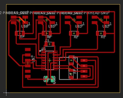
I then started to design what I thought would be my final boards. I would make one communication board that would hold the i2c communication for the lcd display and communicate via tx and rx to the other two boards. You can see the proof of concept for the lcd display back in my Week 11 output week work. I would also make two other boards with sensors and tx/rx communication. These were the designs of said boards:

Then I milled out the boards and soldered them. I realized that I had been using 10k Ohm resistors, before. This time, I ended up switching the resistors to 1M Ohm resistors after doing some research. I found that having a 1M Ohm resistor made it so that it takes more time to charge and settle– this gives me more time to take a reading from the sensor.
I first tested the board with three sensors. This is what I changed the code to:
#include <util/delay.h>

#define CHARGEPIN1 2
#define READPIN1 3
#define CHARGEPIN2 0
#define READPIN2 1
#define CHARGEPIN3 8
#define READPIN3 9
#define settleDelay 100
#define chargeDelay 1

int reading1;
int reading2;
int reading3;

void setup() {
  // put your setup code here, to run once:
  Serial.begin(115200);
  pinMode(CHARGEPIN1, OUTPUT);
  digitalWrite(CHARGEPIN1, LOW);
  pinMode(READPIN1, INPUT);
  pinMode(CHARGEPIN2, OUTPUT);
  digitalWrite(CHARGEPIN2, LOW);
  pinMode(READPIN2, INPUT);
  pinMode(CHARGEPIN3, OUTPUT);
  digitalWrite(CHARGEPIN3, LOW);
  pinMode(READPIN3, INPUT);
  //lcd.begin();
  // Turn on the blacklight and print a message.
  //lcd.backlight();
}

void loop() {
  //settle, charge, and wait
  delay(settleDelay);
  digitalWrite(CHARGEPIN1, HIGH);
  digitalWrite(CHARGEPIN2, HIGH);
  digitalWrite(CHARGEPIN3, HIGH);
  delay(chargeDelay);
  reading1 = analogRead(READPIN1);
  reading2 = analogRead(READPIN2);
  reading3 = analogRead(READPIN3);
  //send result
  Serial.println(reading1);
  Serial.println(reading2);
  Serial.println(reading3);
  Serial.println("");
  if (reading1 < 1015){
    //Serial.clear();
    Serial.print("one");
    delay(100);
  }
  else if (reading2 < 1021){
    //lcd.clear();
    Serial.print("two");
    delay(100);
  }
  else if (reading3 < 1015){
    //lcd.clear();
    Serial.print("three");
    delay(100);
  }
}
It worked well!
Then I went on to the four sensor board. I first only printed out the values the sensor was reading to see what numbers I would use for all my if statements. I found that only my second and fourth values weren’t changing. So, I tried to switch the read and charge pins for each of those. I found that this worked! I then set up my if statements, and this is what I got!
#include <util/delay.h>

#define CHARGEPIN1 2
#define READPIN1 3
#define CHARGEPIN2 1
#define READPIN2 0
#define CHARGEPIN3 8
#define READPIN3 9
#define CHARGEPIN4 7
#define READPIN4 6
#define settleDelay 100
#define chargeDelay 1

int reading1;
int reading2;
int reading3;
int reading4;

void setup() {
  // put your setup code here, to run once:
  Serial.begin(115200);
  pinMode(CHARGEPIN1, OUTPUT);
  digitalWrite(CHARGEPIN1, LOW);
  pinMode(READPIN1, INPUT);
  pinMode(CHARGEPIN2, OUTPUT);
  digitalWrite(CHARGEPIN2, LOW);
  pinMode(READPIN2, INPUT);
  pinMode(CHARGEPIN3, OUTPUT);
  digitalWrite(CHARGEPIN3, LOW);
  pinMode(READPIN3, INPUT);
  pinMode(CHARGEPIN4, OUTPUT);
  digitalWrite(CHARGEPIN4, LOW);
  pinMode(READPIN4, INPUT);
}

void loop() {
  //settle, charge, and wait
  delay(settleDelay);
  digitalWrite(CHARGEPIN1, HIGH);
  digitalWrite(CHARGEPIN2, HIGH);
  digitalWrite(CHARGEPIN3, HIGH);
  digitalWrite(CHARGEPIN4, HIGH);
  delay(chargeDelay);
  reading4 = analogRead(READPIN4);
  reading1 = analogRead(READPIN1);
  reading3 = analogRead(READPIN3);
  reading2 = analogRead(READPIN2);
  //send result
  Serial.print(reading1);
  Serial.print(",");
  Serial.print(reading2);
  Serial.print(",");
  Serial.print(reading3);
  Serial.print(",");
  Serial.print(reading4);
  Serial.println("");
  if (reading1 > 850){ // min: 820
    Serial.println("");
    Serial.println("four");
    delay(100);
  }
  else if (reading2 < 1005 && reading2 > 990 ){ // max: 1020
    Serial.println("");
    Serial.println("five");
    delay(100);
  }
  else if (reading3 < 980){ // max: 990
    Serial.println("");
    Serial.println("six");
    delay(100);
  }
  else if (reading4 < 100){ //max:220
    Serial.println("");
    Serial.println("seven");
    delay(100);
  }
}
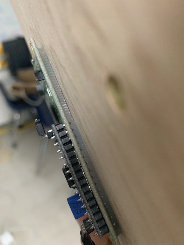
Afterwards, I found that my boards were very unstable. The values for the if statement had to be constantly changed, so I tried to ground it somehow. I found a spare piece of wood and decided to hang the board in free air (without touching anything) and place the sensors on the wood. I found that all the values began to stablize- no more 200’s. All the boards hovered around 1023, making it much easier to find a threshold value. I made that value 1002, and found that they worked well. Here are the videos of them working!
#include <util/delay.h>

#define CHARGEPIN1 2
#define READPIN1 3
#define CHARGEPIN2 0
#define READPIN2 1
#define CHARGEPIN3 8
#define READPIN3 9
#define settleDelay 100
#define chargeDelay 1

int reading1;
int reading2;
int reading3;

void setup() {
  // put your setup code here, to run once:
  Serial.begin(115200);
  pinMode(CHARGEPIN1, OUTPUT);
  digitalWrite(CHARGEPIN1, LOW);
  pinMode(READPIN1, INPUT);
  pinMode(CHARGEPIN2, OUTPUT);
  digitalWrite(CHARGEPIN2, LOW);
  pinMode(READPIN2, INPUT);
  pinMode(CHARGEPIN3, OUTPUT);
  digitalWrite(CHARGEPIN3, LOW);
  pinMode(READPIN3, INPUT);
}

void loop() {
  //settle, charge, and wait
  delay(settleDelay);
  digitalWrite(CHARGEPIN1, HIGH);
  digitalWrite(CHARGEPIN2, HIGH);
  digitalWrite(CHARGEPIN3, HIGH);
  delay(chargeDelay);
  reading1 = analogRead(READPIN1);
  reading2 = analogRead(READPIN2);
  reading3 = analogRead(READPIN3);
  //send result
  /*
  Serial.print(reading1);
  Serial.print(",");
  Serial.print(reading2);
  Serial.print(",");
  Serial.print(reading3);
  Serial.println("");
  */
  if (reading1 < 1002){
    //Serial.clear();
    Serial.println("one");
    delay(200);
  }
  else if (reading2 < 1002){
    //lcd.clear();
    Serial.println("two");
    delay(200);
  }
  else if (reading3 < 1002){
    //lcd.clear();
    Serial.println("three");
    delay(200);
  }
}
Now that I knew this worked, I commented out the printing of the values so that only the sensor positions would be printed. It was then time to code the communications board. I would also need to include software serial. I referenced my code from week 14 (networking and communications week) for the lines of code needed to implement the software serial communication. Before I started, I realized that I would need the hardware tx and rx pins for Processing, so I had to redesign the board in such a way that I could plug in the FTDI chip.
This is what my board looked like milled and soldered:
To learn how to read multiple characters from the serial port, I found this tutorial on different examples of Serial Input Basics. I messed around with the code, and decided to start with an example code from the SoftwareSerial library. To test if I could communicate between boards, I used the SoftwareSerialExample example. Unfortunately, nothing happened. I talked with Dr. Harris, one of our Fab Academy instructors, and decided to update the code of the sensor boards to make it easier to communicate. Instead of printing strings like one, two, and three, I would just print an array of four numbers, 0 representing no touch and 1 representing touch. This way, it would be easier to parse through the reading and decide what is needed to be printed. I also changed the baud rate to the rate shown on the example. This is the code that I ended up getting for the sensor boards.
#include <util/delay.h>

#define CHARGEPIN1 2
#define READPIN1 3
#define CHARGEPIN2 1
#define READPIN2 0
#define CHARGEPIN3 8
#define READPIN3 9
#define CHARGEPIN4 7
#define READPIN4 6
#define settleDelay 100
#define chargeDelay 1

int reading1;
int reading2;
int reading3;
int reading4;

void setup() {
  // put your setup code here, to run once:
  Serial.begin(9600);
  pinMode(CHARGEPIN1, OUTPUT);
  digitalWrite(CHARGEPIN1, LOW);
  pinMode(READPIN1, INPUT);
  pinMode(CHARGEPIN2, OUTPUT);
  digitalWrite(CHARGEPIN2, LOW);
  pinMode(READPIN2, INPUT);
  pinMode(CHARGEPIN3, OUTPUT);
  digitalWrite(CHARGEPIN3, LOW);
  pinMode(READPIN3, INPUT);
  pinMode(CHARGEPIN4, OUTPUT);
  digitalWrite(CHARGEPIN4, LOW);
  pinMode(READPIN4, INPUT);
}

void loop() {
  //settle, charge, and wait
  delay(settleDelay);
  digitalWrite(CHARGEPIN1, HIGH);
  digitalWrite(CHARGEPIN2, HIGH);
  digitalWrite(CHARGEPIN3, HIGH);
  digitalWrite(CHARGEPIN4, HIGH);
  delay(chargeDelay);
  reading4 = analogRead(READPIN4);
  reading1 = analogRead(READPIN1);
  reading3 = analogRead(READPIN3);
  reading2 = analogRead(READPIN2);
  //send result
  /*
  Serial.print(reading1);
  Serial.print(",");
  Serial.print(reading2);
  Serial.print(",");
  Serial.print(reading3);
  Serial.print(",");
  Serial.print(reading4);
  Serial.println("");
  */
  if (reading1 < 1002){
    //Serial.println("");
    Serial.print("1");
    delay(200);
  }
  else Serial.print("0");

  if (reading2 < 1002 ){
    Serial.print("1");
  }
  else Serial.print("0");

  if (reading3 < 1002){
    Serial.print("1");
  }
  else Serial.print("0");

  if (reading4 < 1002){
    //Serial.println("");
    Serial.print("1");
  }
  else Serial.print("0");
  Serial.println();
}
#include <util/delay.h>

#define CHARGEPIN1 2
#define READPIN1 3
#define CHARGEPIN2 0
#define READPIN2 1
#define CHARGEPIN3 8
#define READPIN3 9
#define settleDelay 100
#define chargeDelay 1

int reading1;
int reading2;
int reading3;

//button variables that = 0
int count = 0;

void setup() {
  // put your setup code here, to run once:
  Serial.begin(9600);
  pinMode(CHARGEPIN1, OUTPUT);
  digitalWrite(CHARGEPIN1, LOW);
  pinMode(READPIN1, INPUT);
  pinMode(CHARGEPIN2, OUTPUT);
  digitalWrite(CHARGEPIN2, LOW);
  pinMode(READPIN2, INPUT);
  pinMode(CHARGEPIN3, OUTPUT);
  digitalWrite(CHARGEPIN3, LOW);
  pinMode(READPIN3, INPUT);
}

void loop() {
  //settle, charge, and wait
  delay(settleDelay);
  digitalWrite(CHARGEPIN1, HIGH);
  digitalWrite(CHARGEPIN2, HIGH);
  digitalWrite(CHARGEPIN3, HIGH);
  delay(chargeDelay);
  reading1 = analogRead(READPIN1);
  reading2 = analogRead(READPIN2);
  reading3 = analogRead(READPIN3);
  //send result
  /*
  Serial.print(reading1);
  Serial.print(",");
  Serial.print(reading2);
  Serial.print(",");
  Serial.print(reading3);
  Serial.println("");
  */
  if (reading1 < 1005){
    //Serial.clear();
    Serial.print("1");
  }
  else Serial.print("0");

  if (reading2 < 1005){
    //lcd.clear();
    Serial.print("1");
  }
  else Serial.print("0");

  if (reading3 < 1005){
    //lcd.clear();
    Serial.print("1");
  }
  else Serial.print("0");
  Serial.println();
}
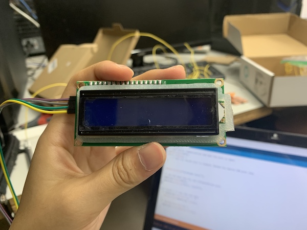
After programming the board and testing it, I found that it worked!
The strings in the setup method and loop method didn’t print, but it was reading what the sensor board was outputting! Now I wanted to add the other sensor board to the communication setup. I copied the code I had for the communication board, changed the lcd display, and programmed it. This is the code I had:
#include <SoftwareSerial.h>
#include <Wire.h>
#include <LiquidCrystal_I2C.h>

SoftwareSerial mySerial1(2, 3); // RX, TX
SoftwareSerial mySerial2(3, 2);
String readFour = "";
String readThree = "";

int count = 0;
int counta = 0;
LiquidCrystal_I2C lcd(0x27, 16, 2);

void setup() {
  // Open serial communications and wait for port to open:
  Serial.begin(57600);
  while (!Serial) {
    ; // wait for serial port to connect. Needed for native USB port only
  }
  // set the data rate for the SoftwareSerial port
  mySerial1.begin(9600);
  mySerial2.begin(9600);
  lcd.begin();
  lcd.backlight();
}

void loop() { // run over and over
  //
  // four sensor board
  //
  mySerial1.listen();
   while (mySerial1.available() > 0){
    char c = mySerial1.read();
    readFour += c;
    count++;
    if (count == 4){
      count = 0;
      if (readFour.substring(0,1).equals("1")){
        lcd.clear();
        lcd.print("North America");
        //delay(400);
      }
      if (readFour.substring(1,2).equals("1")){
        lcd.clear();
        lcd.print("South America");
        //delay(400);
      }
      if (readFour.substring(2,3).equals("1")){
        lcd.clear();
        lcd.print("Europe");
        //delay(400);
      }
      if (readFour.substring(3).equals("1")){
        lcd.clear();
        lcd.print("Africa");
        //delay(400);
      }
    }
    if (c =='\n'){
      Serial.print(readFour);
      readFour = "";
    }
   }
   //
   //three sensor board
   //
   /*
   mySerial2.listen();
   while (mySerial2.available() > 0){
    char h = mySerial2.read();
    readThree += h;
    counta++;
    if (counta == 4){
      counta = 0;
      if (readThree.substring(0,1).equals("1")){
        lcd.clear();
        lcd.print("North America");
        //delay(400);
      }
      if (readThree.substring(1,2).equals("1")){
        lcd.clear();
        lcd.print("South America");
        //delay(400);
      }
      if (readThree.substring(2).equals("1")){
        lcd.clear();
        lcd.print("Europe");
        //delay(400);
      }
    }
    if (h =='\n'){
      Serial.print(readThree);
      readThree = "";
    }
   }
   */
}
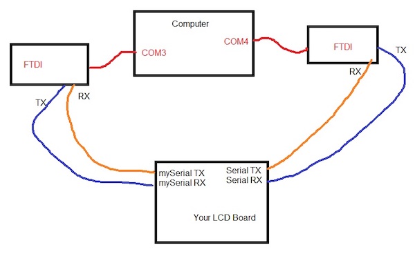
Unfortunately, nothing happened. The output on the serial monitor came up very weird and janky. So, I tried to copy the exact same code I used for the previous test except with the other serial port communication– I suspected something was wrong with the port itself (pins 2 and 3). I emailed Dr. Harris, one of our Fab instructors, and he recommended that I plug in two ftdi chips into my computer. He suggested that I open one Serial terminal in CoolTerm on one COM channel, and the other Arduino terminal on the other COM channel (as shown in the picture below).
I did the test using CoolTerm and found that I could communicate between the two serials, meaning that there was nothing wrong with my board itself. I went back to trying to program the boards. Dr. Harris found this link that had some example code. I tried to start simple. I first used the code to test if I could communicate with one sensor board– I could. I then changed the pins on the code’s software serial to test the other sensor board– it also worked. However, after I tried to copy and paste the code so that I could try both sensor boards at the same time, it wouldn’t work.
#include <SoftwareSerial.h>

    SoftwareSerial mySerial(1, 0); // RX, TX
    String data = "";

    void setup()
    {
        mySerial.begin(9600);
    }

    void loop() // run over and over
    {
      while(mySerial.available()==0)
      {}

      char character;
      while(mySerial.available()>0)
      {
        character = mySerial.read();
        mySerial.write(character);
      }

      data += character;

      if (character == 13) {
        mySerial.print("Received: ");
        mySerial.println(data);
        data = "";
      }
    }
I even tried using the .listen() method and a .stopListening() method Dr. Harris told me about, but it didn’t work. Each sensor board was sending the right data, but the communication board wasn’t receiving it properly.
Frustrated, I decided to try to use only one software serial. I found that I could use the ATtiny3216, as it has many pins. The plan was to have I2C communication, four sensors, and tx/rx communication on a board with the ATtiny3216, and four sensors on the sensor board with an ATtiny1614. (This way I would have one extra sensor if something went wrong). I referenced the ATtiny3216 datasheet to look at the chip’s pinout and capabilities. The main reason I chose this chip was because of its use of UPDI programming, its number of pins, and its memory space (32 KB Flash, 2 KB SRAM and 256 bytes of EEPROM).
Final Boards
Big Board
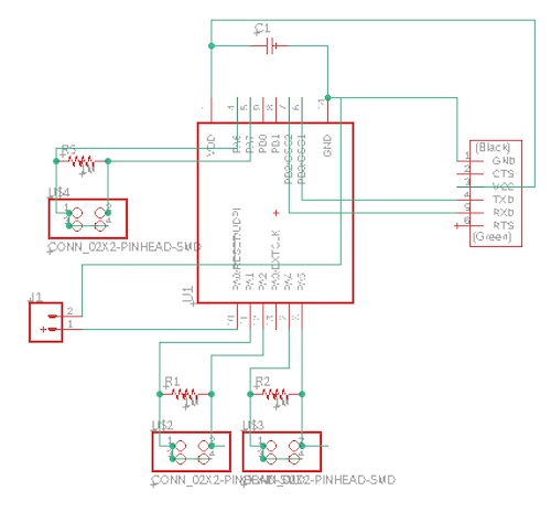
I first sketched out what pins I needed for I2C communication, tx/rx communication, and four sensors.

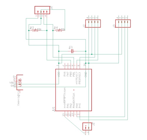
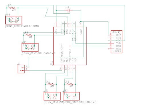
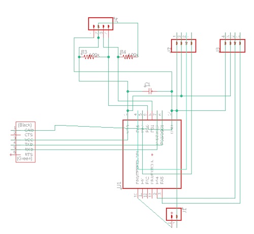
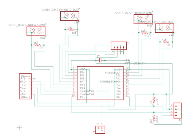
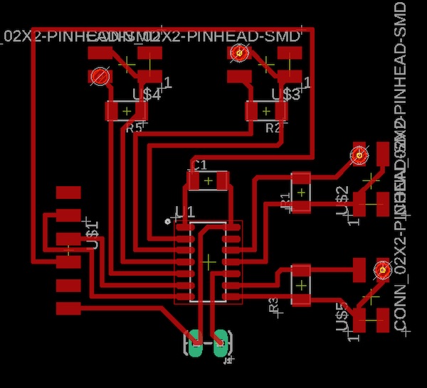
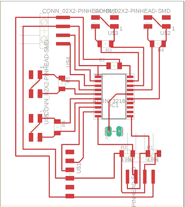
I then started to make the schematic on EAGLE. After adding all the components I needed, this is what it looked like:
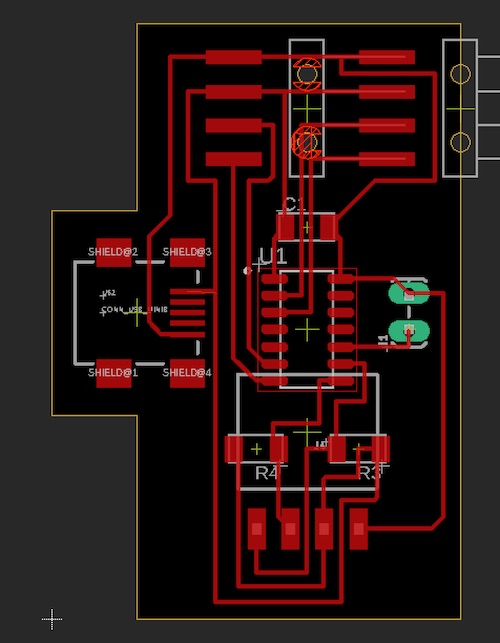
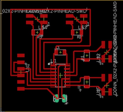
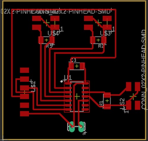
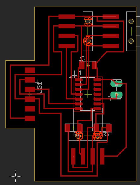
I then switched to the .brd file side of EAGLE. I arranged the parts on the board and tried to make it as symmetrical/balanced as I could, and this is what I got:
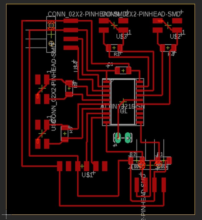
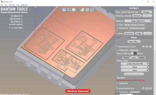
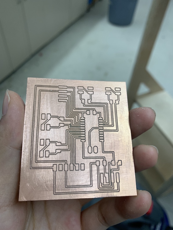
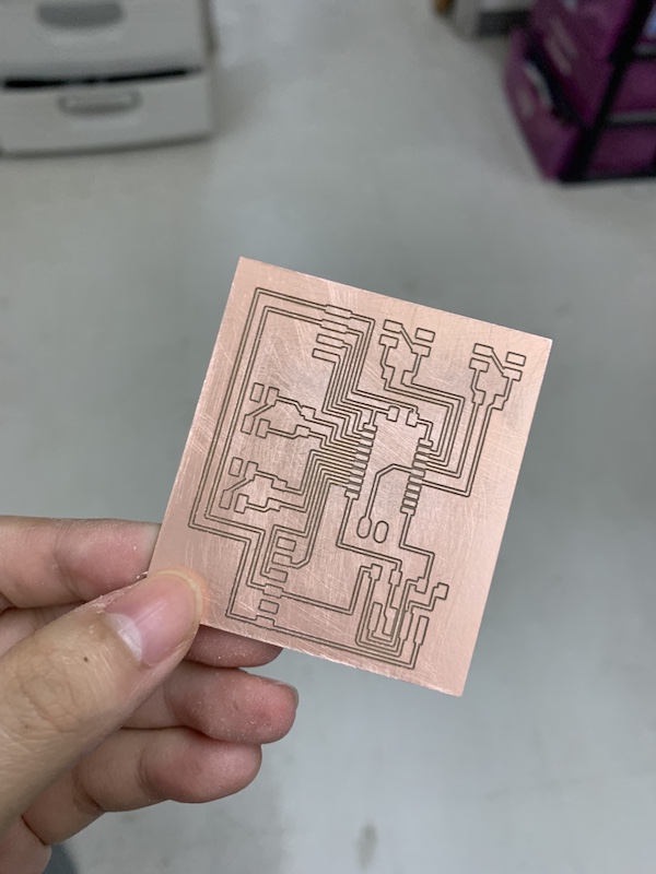
After importing the .brd file into Bantam Tools, I used a 1/64” drill flat end bit to mill out the traces. I then used a 1/16” bit to cut the outline.
I found a lot of copper burrs, so I went to postprocess the board. I sanded it down with a piece of P220 sand paper and used an old brush to brush away and debris. It was much smoother after the postprocessing.
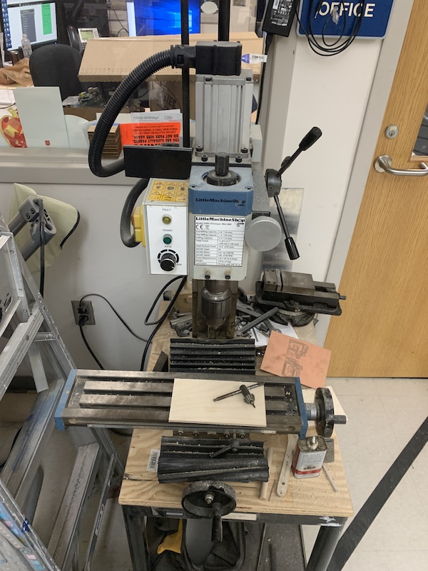
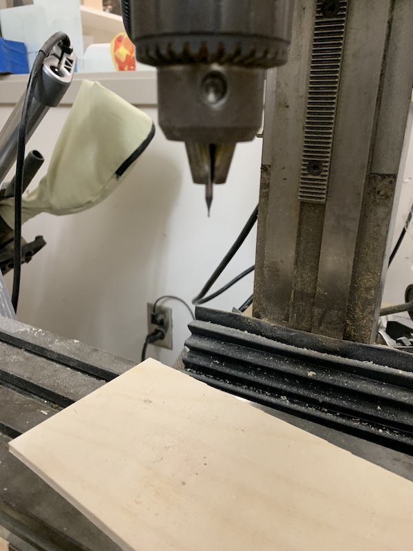
I realized I forgot to add holes in my design for the sensor wires. So, I used the Multi-tool Drill Press to drill some holes with a 1/32” bit. While on, I lowered the drill bit onto each read pin on my board. It turned out pretty nicely!
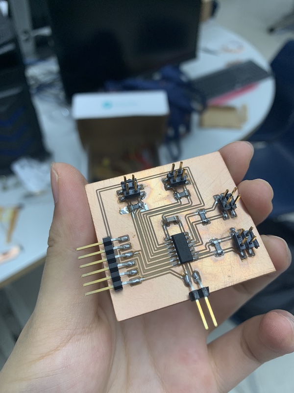
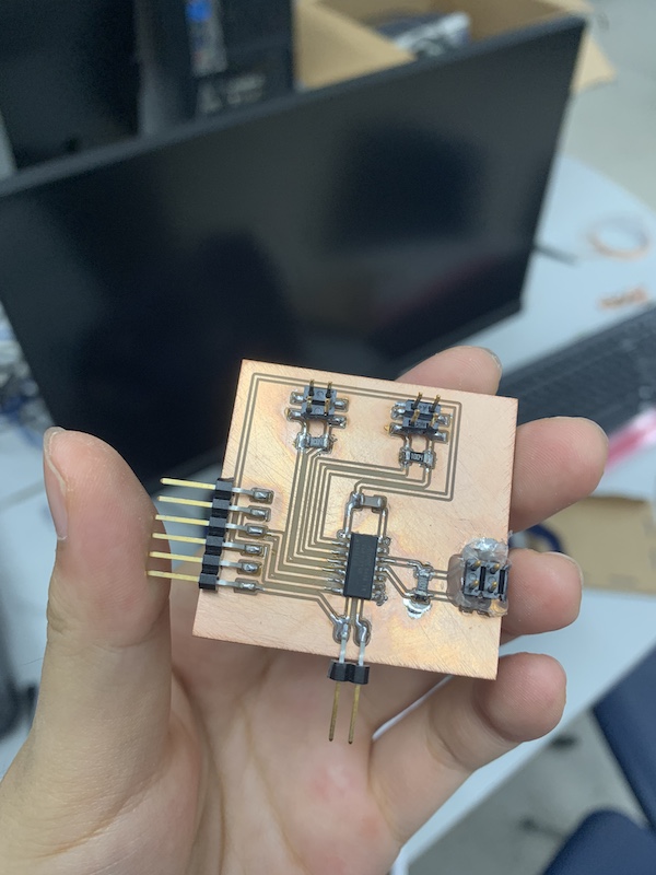
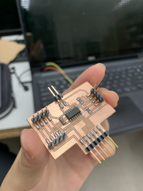
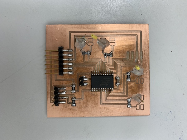
It was time to solder! I soldered on all the components and it turned out pretty good!
I realized that in designing my board, I had accidentally switched the fdti pins on the board. So, I used 6x1 pin header adapters to connect my ftdi chip. Other than that, it was all good.
Sensor Board
I had a working sensor board, but for my project, I needed a board with holes instead of pinheaders so that I could push the sensor wires into them. I did the same for the Big Board above. Instead of using the Drill Press, I added holes in the design of my board. All I did was use the Hole tool on the BRD side of EAGLE and added holes of diameter 20 onto each sensor’s read pin. I milled it out, postprocessed it, and soldered it.
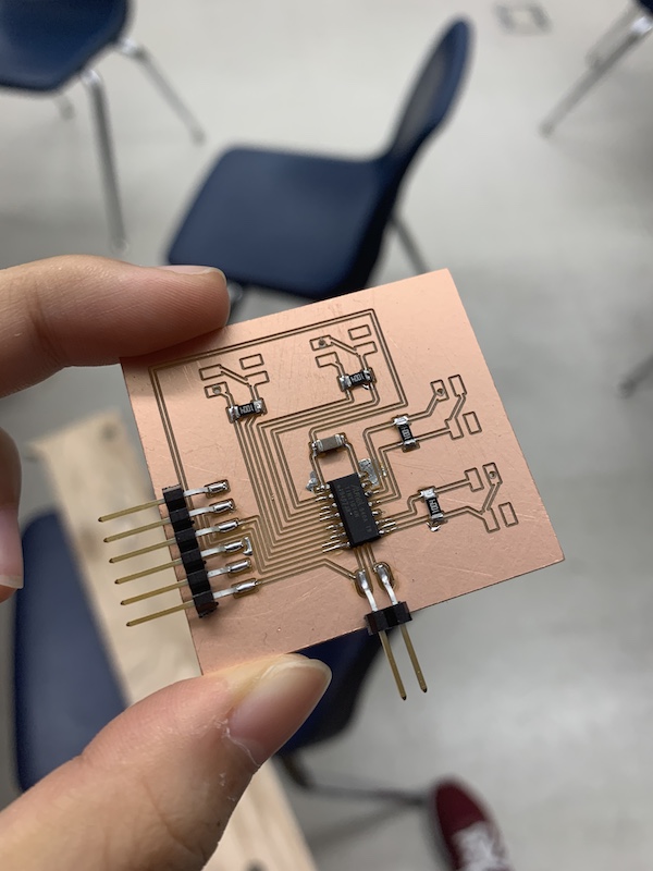
I then used the same code I used for the previous sensor board for this one. It worked!
#include <util/delay.h>

#define CHARGEPIN1 2
#define READPIN1 3
#define CHARGEPIN2 1
#define READPIN2 0
#define CHARGEPIN3 8
#define READPIN3 9
#define CHARGEPIN4 7
#define READPIN4 6
#define settleDelay 100
#define chargeDelay 1

int reading1;
int reading2;
int reading3;
int reading4;

void setup() {
  // put your setup code here, to run once:
  Serial.begin(9600);
  pinMode(CHARGEPIN1, OUTPUT);
  digitalWrite(CHARGEPIN1, LOW);
  pinMode(READPIN1, INPUT);
  pinMode(CHARGEPIN2, OUTPUT);
  digitalWrite(CHARGEPIN2, LOW);
  pinMode(READPIN2, INPUT);
  pinMode(CHARGEPIN3, OUTPUT);
  digitalWrite(CHARGEPIN3, LOW);
  pinMode(READPIN3, INPUT);
  pinMode(CHARGEPIN4, OUTPUT);
  digitalWrite(CHARGEPIN4, LOW);
  pinMode(READPIN4, INPUT);
}

void loop() {
  //settle, charge, and wait
  delay(settleDelay);
  digitalWrite(CHARGEPIN1, HIGH);
  digitalWrite(CHARGEPIN2, HIGH);
  digitalWrite(CHARGEPIN3, HIGH);
  digitalWrite(CHARGEPIN4, HIGH);
  delay(chargeDelay);
  reading4 = analogRead(READPIN4);
  reading1 = analogRead(READPIN1);
  reading3 = analogRead(READPIN3);
  reading2 = analogRead(READPIN2);
  //send result
  /*
  Serial.print(reading1);
  Serial.print(",");
  Serial.print(reading2);
  Serial.print(",");
  Serial.print(reading3);
  Serial.print(",");
  Serial.print(reading4);
  Serial.println("");
  */
  if (reading1 < 1014){
    //Serial.println("");
    Serial.print("1");
  }
  else Serial.print("0");

  if (reading2 < 1011){
    Serial.print("1");
  }
  else Serial.print("0");

  if (reading3 < 1014){
    Serial.print("1");
  }
  else Serial.print("0");

  if (reading4 < 1015){
    Serial.print("1");
  }
  else Serial.print("0");
  Serial.println();
}
Programming
For programming the big board, I started off making sure that the board’s sensors, software serial communication, and lcd display worked. I referenced all the codes I had used so far. To test the sensors, I used the if statements and sensor readings from the sensor boards. To test the software serial reading, I used the code from the previous attempt at the communication board. To test the lcd display, I used the .print() methods from the output board back in week 11. I wanted to split up the code into different methods: one for reading the software serial, one for reading the sensors on the big board itself, and one method for parsing the string to print something on the LCD display. The idea for the code was that I would first read the sensors on the big board, add the string to a global variable, then read the sensors on the software serial sensor board and add it to the global string variable. I would then parse through it and use a series of if statements to see what needed to be printed. This is the code I wrote:
#include <SoftwareSerial.h>
#include <Wire.h>
#include <LiquidCrystal_I2C.h>
#include <util/delay.h>

#define CHARGEPIN1 13
#define READPIN1 14
#define CHARGEPIN2 15
#define READPIN2 16
#define CHARGEPIN3 2
#define READPIN3 3
#define CHARGEPIN4 4
#define READPIN4 5
#define settleDelay 100
#define chargeDelay 1

SoftwareSerial mySerial1(1, 0); // RX, TX
String readFour = "";
int count = 0;
String sensors = "";

LiquidCrystal_I2C lcd(0x27, 16, 2);

void setup() {
  //serial setup
  // Open serial communications and wait for port to open:
  Serial.begin(57600);
  while (!Serial) {
    ; // wait for serial port to connect. Needed for native USB port only
  }
  mySerial1.begin(9600);

  //sensor setup
  pinMode(CHARGEPIN1, OUTPUT);
  digitalWrite(CHARGEPIN1, LOW);
  pinMode(READPIN1, INPUT);
  pinMode(CHARGEPIN2, OUTPUT);
  digitalWrite(CHARGEPIN2, LOW);
  pinMode(READPIN2, INPUT);
  pinMode(CHARGEPIN3, OUTPUT);
  digitalWrite(CHARGEPIN3, LOW);
  pinMode(READPIN3, INPUT);
  pinMode(CHARGEPIN4, OUTPUT);
  digitalWrite(CHARGEPIN4, LOW);
  pinMode(READPIN4, INPUT);

  // lcd setup
  lcd.begin();
  lcd.backlight();
}

void loop() { // run over and over
  sensors += readsensors(); // first four sensors
  sensors += othersensors(); // other sensors
  parsesensors(sensors); // parse through the sensors
  sensors = ""; //reset sensors
}

String readsensors(){
  String ownSensor = "";
  int reading1;
  int reading2;
  int reading3;
  int reading4;
  //settle, charge, and wait
  delay(settleDelay);
  digitalWrite(CHARGEPIN1, HIGH);
  digitalWrite(CHARGEPIN2, HIGH);
  digitalWrite(CHARGEPIN3, HIGH);
  digitalWrite(CHARGEPIN4, HIGH);
  delay(chargeDelay);
  reading4 = analogRead(READPIN4);
  reading1 = analogRead(READPIN1);
  reading3 = analogRead(READPIN3);
  reading2 = analogRead(READPIN2);
  //send result
  /* for debugging and calibrating the sensors
  Serial.print(reading1);
  Serial.print(",");
  Serial.print(reading2);
  Serial.print(",");
  Serial.print(reading3);
  Serial.print(",");
  Serial.print(reading4);
  Serial.println("");
  */
  if (reading1 < 1013){
    //Serial.println("");
    ownSensor += "1";
  }
  else ownSensor += "0";

  if (reading2 < 1013){
    ownSensor += "1";
  }
  else ownSensor += "0";

  if (reading3 < 1013){
    ownSensor += "1";
  }
  else ownSensor += "0";

  if (reading4 < 1013){
    //Serial.println("");
    ownSensor += "1";
  }
  else ownSensor += "0";
  return ownSensor;
}

String othersensors(){
  mySerial1.listen();
  while (mySerial1.available() > 0){
     char c = mySerial1.read();
     readFour += c;
     count++;
     if (count == 4){
       count = 0;
     }
     if (c == 13){
       return readFour;
       readFour = "";
       mySerial1.stopListening();
     }
  }
}

void parsesensors(String sensor){
  if (sensor.substring(0,1).equals("1")){
    lcd.clear();
    lcd.print("North America");
  }
  if (sensor.substring(1,2).equals("1")){
    lcd.clear();
    lcd.print("South America");
  }
  if (sensor.substring(2,3).equals("1")){
    lcd.clear();
    lcd.print("Africa");
  }
  if (sensor.substring(3,4).equals("1")){
    lcd.clear();
    lcd.print("Antarctica");
  }
  if (sensors.substring(4,5).equals("1")){
    lcd.clear();
    lcd.print("Australia");
  }
  if (sensors.substring(5,6).equals("1")){
    lcd.clear();
    lcd.print("Asia");
  }
  if (sensors.substring(6,7).equals("1")){
    lcd.clear();
    lcd.print("Europe");
  }
}
After testing it, I found that nothing worked. So, I started from the basics. I first made sure that the LCD display worked with the board. I commented out everything except for the lines of code setting up the display and printing out “hi”. I found that this worked. After changing the LCD display to use the if statements, I tested the sensors themselves using the lines of code for reading sensor values, and I found that this worked too. The video shows the if statements working with the sensors themselves.
Finally, I tested that software serial communication could work with the sensor board. This worked as well. So, I knew that each part of my code above worked separately in the void loop() method. So, I tried putting each code segment into its own method one at a time and checking if it still worked. I found that the software serial lines of code would not work when it was in its own method. So, I put it in the void loop() method. This is what the body of the code looked like now.
void loop() { // run over and over
  sensors += readsensors(); // first four sensors
  mySerial1.listen();
  while (mySerial1.available() > 0){
     char c = mySerial1.read();
     readFour += c;
     count++;
     if (count == 4){
       count = 0;
     }
     if (c == 13){
       sensors += readFour;
       Serial.println(sensors);
       parsesensors(sensors);
       readFour = "";
       mySerial1.stopListening();
     }
  }
  sensors = "";
}

String readsensors(){
  String ownSensor = "";
  int reading1;
  int reading2;
  int reading3;
  int reading4;
  //settle, charge, and wait
  delay(settleDelay);
  digitalWrite(CHARGEPIN1, HIGH);
  digitalWrite(CHARGEPIN2, HIGH);
  digitalWrite(CHARGEPIN3, HIGH);
  digitalWrite(CHARGEPIN4, HIGH);
  delay(chargeDelay);
  reading4 = analogRead(READPIN4);
  reading1 = analogRead(READPIN1);
  reading3 = analogRead(READPIN3);
  reading2 = analogRead(READPIN2);
  //send result
  /* for debugging and calibrating the sensors
  Serial.print(reading1);
  Serial.print(",");
  Serial.print(reading2);
  Serial.print(",");
  Serial.print(reading3);
  Serial.print(",");
  Serial.print(reading4);
  Serial.println("");
  */
  if (reading1 < 1013){
    //Serial.println("");
    ownSensor += "1";
  }
  else ownSensor += "0";

  if (reading2 < 1013){
    ownSensor += "1";
  }
  else ownSensor += "0";

  if (reading3 < 1013){
    ownSensor += "1";
  }
  else ownSensor += "0";

  if (reading4 < 1013){
    //Serial.println("");
    ownSensor += "1";
  }
  else ownSensor += "0";
  return ownSensor;
}

void parsesensors(String sensor){
  if (sensor.substring(0,1).equals("1")){
    lcd.clear();
    lcdwrite("North America");
  }
  if (sensor.substring(1,2).equals("1")){
    lcd.clear();
    lcdwrite("South America");
  }
  if (sensor.substring(2,3).equals("1")){
    lcd.clear();
    lcdwrite("Africa");
  }
  if (sensor.substring(3,4).equals("1")){
    lcd.clear();
    lcdwrite("Antarctica");
  }
  if (sensors.substring(4,5).equals("1")){
    lcd.clear();
    lcdwrite("Australia");
  }
  if (sensors.substring(5,6).equals("1")){
    lcd.clear();
    lcdwrite("Asia");
  }
  if (sensors.substring(6,7).equals("1")){
    lcd.clear();
    lcdwrite("Europe");
  }
}
I was glad to see that this worked! This video shows everything except the lcd display working together– the software serial communication, the sensors, and the concatenation.
Note: Before I moved on with the code, I assembled the front piece of the project (I wanted to do this so that I could calibrate any sensor value thresholds if needed with the continent sensors, although they didn’t end up needing any calibration– lucky me!). Visit the assembly section down below to see how I did this. After it was assembled, I continued to dabble with the code…
This is what the project looked like so far with the sensors in the front piece of the frame:
The code did feel a little lackluster with the LCD simply printing out words. I wanted to try out what a scroll effect would look like. So, I referenced fab alumni Kai Vincent’s output week code where he tested out a scrolling effect. I made a new method called lcdwrite(String str) that would take in a string and have the scroll effect while printing. This is what the method looked like:
void lcdwrite(String str){
  lcd.setCursor(0, 0);
  // print from 0 to 9:
  for (int i =0; i < str.length(); i++){
    lcd.print(str.substring(i, i+1));
    delay(500);
  }
  // set the cursor to (16,0):
  lcd.setCursor(16, 0);
  // set the display to automatically scroll:
  lcd.autoscroll();
  // print from 0 to 9:
  for (int i = 0; i < str.length(); i++) {
    lcd.print(str.substring(i,i+1));
    delay(500);
  }
  // turn off automatic scrolling
  lcd.noAutoscroll();
}
For the if statements, instead of using lcd.print(), I used lcdwrite(). It worked well!
However, I didn’t really like the way it worked aesthetically, but I still wanted something more complex than just simply printing. I decided I wanted the display to print each letter one at a time and to position the word in the middle of the display. It was easy to do the positioning part– instead of setting the cursor to (0,0), I set it to (abs((16-str.length())/2), 0). This way, the word would start at a position that allowed the word to sit in the middle of the display. I also kept the for loop that printed each character one at a time. This was my new lcdwrite(String str) method:
void lcdwrite(String str){
  int startint = abs((16-str.length())/2);
  lcd.setCursor(startint, 0);
  // print from 0 to 9:
  for (int i =0; i < str.length(); i++){
    lcd.print(str.substring(i, i+1));
    delay(150);
  }
  delay(1000);
  //if you want the scroll effect:
//  delay(400);
//  // set the cursor to (16,1):
//  lcd.setCursor(16, 1);
//  // set the display to automatically scroll:
//  lcd.autoscroll();
//  // print from 0 to 9:
//  for (int i = 0; i < str.length(); i++) {
//    lcd.print(str.substring(i,i+1));
//    delay(300);
//  }
//  // turn off automatic scrolling
//  lcd.noAutoscroll();
}
I thought this looked much better than before:
Oopsie: I broke the big board
At this point, I was pretty much done with the programming! However, just before I was going to move onto the Processing interface, I accidentally dropped the front frame. In the process, the big board’s I2C communication pins and traces ripped off the board.
Unfortunately, since we didn’t have the reflow gun in the lab, I had to start over again. Big shout out to Vincent Zhou for lending me an ATtiny3216. Either way, I needed to rotate the fdti 6x1 pins in my design so that I could plug in the ftdi chip right side up. I also tried to add holes, but realized that if I milled out those holes, other holes that I didn’t want would also get milled. I made changes to the board design file:
After I used the drill press to drill some holes for the sensors and soldered all the components on, I went through the same process of programming the new board as I did for the previous one. I also resoldered the sensor wires onto the holes. Thankfully, everything worked well. The first picture is the big board after being milled and post processed. The second picture is the entire setup on the back of the front piece, except the lcd display I2C communication wires aren’t hooked up.
Now it was time to move onto the Processing interface.
Processing Interface
I wanted to add a Processing interface that would show images of the sister school[s] in each the continent. I worked on a proof of concept for this back in week 12 for Application Programming. I went to Google images and found images of the 7 sister schools of Charlotte Latin. I used Markup to add words that detailed the name of the school and its location. Here is an example of one of the pictures– this is one of our sister schools in South Africa!

I then dragged and dropped them into my Processing file. This adds it to a data folder of the sketch, allowing me to access the pictures. I referenced my electronics code of the big board to code the interface. I went through setting up each picture and the sketch. The draw() method was mainly just a series of seven if statements. I read what the big board was printing via the hardware serial and used the .substring() method to trigger the images. If a continent didn’t have a sister school, like Antarctica and Australia, I printed the words “Not yet!”. This is what the code looked like:
import processing.serial.*; //imcludes the serial object library

Serial port;  // creates local serial object from Serial library
int maxPinInput = 1023; // maximum value read from sensor
float myVal; // float storing converted ascii serial data
String myString; // variable to collect serial data
PImage italyschool;
PImage soamschool;
PImage franceschool;
PImage hiltonschool;
PImage asiaschool;
PImage germanyschool;
PImage hiltonschoolg;
PImage cls;

void setup() {
  size(600, 400); //size of the sketch
  String portName = Serial.list()[0]; // COM3 was listed as the first port on Arduino (index 0)
  port = new Serial(this, portName, 57600); //instantiating the serial monitor (baud rate must match)
  italyschool = loadImage("italyschool.jpg");
  soamschool = loadImage("soamschool.jpg");
  franceschool = loadImage("franceschool.jpg");
  hiltonschool = loadImage("hiltonschool.jpg");
  asiaschool = loadImage("asiaschool.jpg");
  germanyschool = loadImage("germanyschool.jpg");
  hiltonschoolg = loadImage("hiltonschoolg.jpg");
  cls = loadImage("cls.jpg");
}

void draw() {
   while (port.available() > 0) { //if there is data coming in from the serial monity
     myString = port.readStringUntil(10); //strips data of serial port
     if (myString != null) {
      background(255); // makes background white
       if (myString.substring(0,1).equals("1")){
        clear();
        image(cls, 0, 0);
      }
      if (myString.substring(1,2).equals("1")){
        clear();
        image(soamschool, 0, 0);
      }
      if (myString.substring(2,3).equals("1")){
        clear();
        image(hiltonschool, 0, 0, width/2, height/2);
        image(hiltonschoolg, 300, 200, width/2, height/2);
      }
     if (myString.substring(3,4).equals("1")){
        clear();
        textSize(32);
        text("Not yet!", 10, 40);
      }
      if (myString.substring(4,5).equals("1")){
        clear();
        textSize(32);
        text("Not yet!", 10, 40);
      }
      if (myString.substring(5,6).equals("1")){
        clear();
        image(asiaschool, 0, 0);
      }
      if (myString.substring(6,7).equals("1")){
        clear();
        image(italyschool, 0, 0, width, height/2);
        image(franceschool, 0, 200, width/2, height/2);
        image(germanyschool, 300, 200, width/2, height/2);
      }
    }
  }
}
Unfortunately, it didn’t work exactly the way I wanted it to. Sensors with only one image worked, but Europe and South Africa didn’t. For example, instead of changing images from one school to another for Africa, it only showed the second image. I found that for some reason, delay() methods don’t work between images. So, my solution was to show the images on separate parts of the sketch. I added more parameters to the image() method that specified the dimensions of the images. For example, for Africa, I wrote image(0, 0, width/2, height/2) for one of them and image(300, 200, width/2, height/2). This way, it would show both images when I pressed the sensor at the same time. It worked well!
Assembly
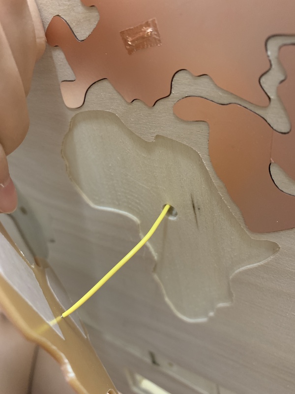
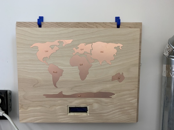
To put my project together, I had to put together the frame and electronics. I had already had the back of the frame made from the CNC frame section of this page. I made put together every part of the frame except for the front piece. After I got to a point in testing my electronics where I felt comfortable that everything would work, I put together the front piece and electronics. I first gathered all my materials. I put a bit of Nitto tape on the back of the sensors, pushed the wire through the hole of the frame, then taped the sensors onto the frame.
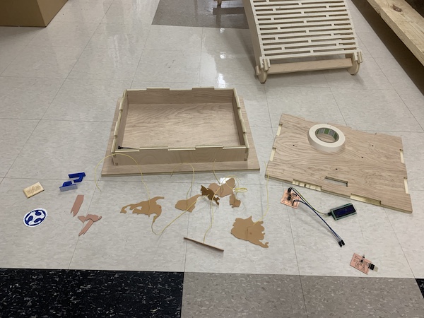
After I did it for all the sensors, I put the LCD display through the display hole. I also eyed out where each board would approximately be and marked their locations with a Sharpie. I cut the wires to an appropriate length that allowed them to easily reach the board. I stripped the ends of the wires then soldered each wire to the holes on the boards.
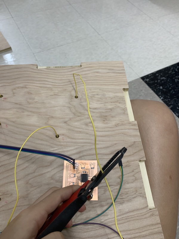
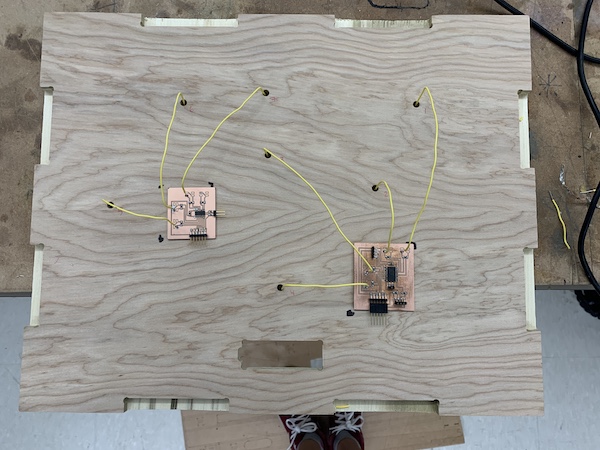
This is what the back looked like without the LCD display.
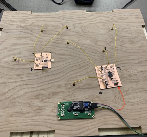
This is what the setup looked like (the LCD display four wires were connected to where the red arrow is). Between this picture and the previous one, I had broken the big board. Reference here to see what happened. Everything worked out in the process though!
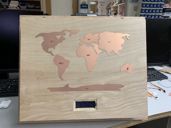
When everything was in place, I put on the front piece of the frame onto the rest of the frame. It took some time, malleting, and kneeling, but it fit on perfectly. This is what the final product looked like.
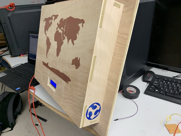
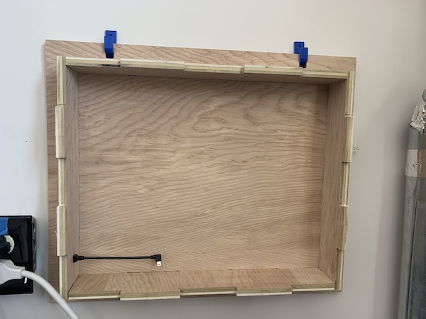
The hooks even worked!
Here’s a video of the project working with the interface!
Files
Here are all my files for this project: Final Files
The files are organized into separate folders for each part of the project!