11. Output Devices
For this week, our individual assignment was to add an output device to a microcontroller board I’ve designed and program it to do something. Our group project was to measure the power consumption of an output device.
Individual Assignment
Designing the Board
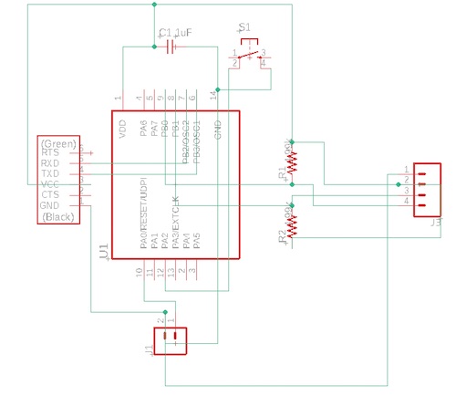
I planned to use an LCD display output for my final project. I referenced Niel’s board when I made my schematic:
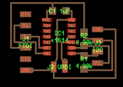
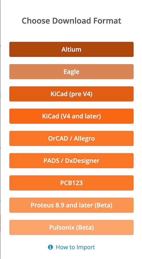
I changed the schematic so that it would work with an ATtiny1614 chip, using the same setup as previous weeks– a 1uF capacitor between VCC and GND, GND to GND on the 6x1 pin header, UPDI to a pin on the 2x1 pin header, MISO to TXD, and MOSI to RXD. At first, I couldn’t find an Eagle library for the ATtiny1614, but I did a quick Google search and found a downloadable version here, although it requires you to make an account if you don’t previously have one. I downloaded the Eagle version.
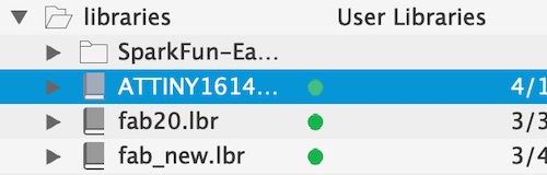
I added the library to my libraries folder and clicked Use.
I added all the components I needed: the ATtiny1614, 2x4.99k Ohm resistors, a 4x1 pin header, a 2x1 pin header, a 6x1 pin header, and a 1uF capacitor.
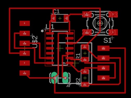
Then I made connections as seen on Niel’s schematic. I also wanted to add another button to the schematic to see if I could control the display using the button. The schematic and board looked like this:
Soldering the Board
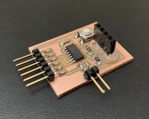
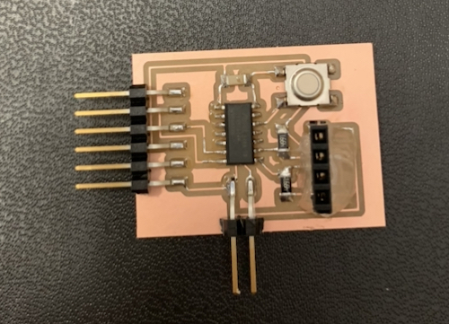
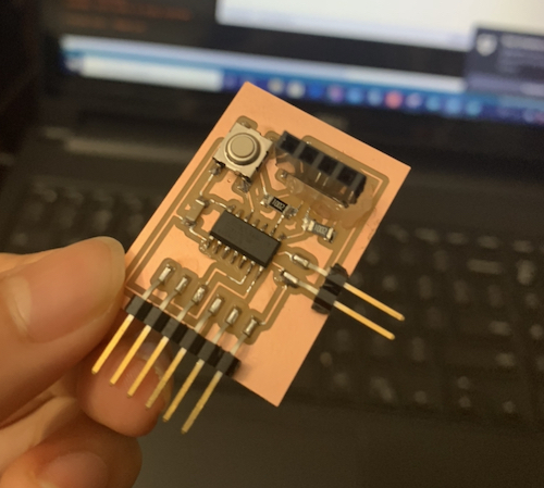
I got all the parts I needed and soldered the components on. Unfortunately, there was some miscommunication between me and Mr. Rudolph, my engineering teacher and one of the Fab Instructors, so I had to solder on vertical female headers onto pads without holes. It worked in the end though.
Programming the Board
As for the other parts, I recieved an LCD display without i2c communcation, an OLED display, and a small OLED display with i2c communication (the SSD1306). I ended up using the small OLED display, since I guessed that it would work best with the board I had. I found this tutorial on using a similar display, and in it, two libraries were recommended: the Adafruit_SSD1306 library and the Adafruit-GFX-Library. I downloaded both of them. I started with copying and pasting the example code that was provided in the tutorial, just to see if anything would happen.
#include <SPI.h>
#include <Wire.h>
#include <Adafruit_GFX.h>
#include <Adafruit_SSD1306.h>

#define SCREEN_WIDTH 128 // OLED display width, in pixels
#define SCREEN_HEIGHT 32 // OLED display height, in pixels

// Declaration for an SSD1306 display connected to I2C (SDA, SCL pins)
#define OLED_RESET     4 // Reset pin # (or -1 if sharing Arduino reset pin)
Adafruit_SSD1306 display(SCREEN_WIDTH, SCREEN_HEIGHT, &Wire, OLED_RESET);

void setup(){
  display.display();
  delay(2000);
  display.clearDisplay();
  display.setTextSize(8);
  display.setCursor(20,16);
  display.print("helloworld");
  display.display();
  }

void loop(){
}
Unfortunately, nothing happened. Just in case the error was caused by a solder problem, I used my multimeter to check that the pin headers were properly soldered onto the pads. They were. Still nothing worked. I then tested a multitude of things, from code syntax (different method/parameters), to baud rate (I tried 2000000), to reset pin (I tried 0), initialization (0x3C vs 0x3D (use 0x3C for the 128x32 display)). I found the following code on the aforementioned tutorial and tried it out before and after editing a few things.
#include <Adafruit_SSD1306.h>
#include <splash.h>

#include <Adafruit_GFX.h>
#include <Adafruit_SPITFT.h>
#include <Adafruit_SPITFT_Macros.h>
#include <gfxfont.h>

#define SCREEN_WIDTH 128 // OLED display width, in pixels
#define SCREEN_HEIGHT 32 // OLED display height, in pixels

#define OLED_RESET     0 // Reset pin # (or -1 if sharing Arduino reset pin)
Adafruit_SSD1306 display(SCREEN_WIDTH, SCREEN_HEIGHT, &Wire, OLED_RESET);

void setup() {
  Serial.begin(2000000);
  if(!display.begin(SSD1306_SWITCHCAPVCC,0x3C)){
    Serial.println(F("SSD1306 allocation failed"));
    for(;;);
  }
  delay(2000);
  display.clearDisplay();
  display.setTextSize(1);
  display.setTextColor(SSD1306_WHITE);
  display.setCursor(0,10);
  display.print("hello world");
  display.display();

}

void loop() {
  // put your main code here, to run repeatedly:

}
Still, nothing happened. At this point, it’d been around an hour. I was starting to get a little confused/frustrated. I googled around some more before asking Mr. Rudolph about my errors. I tried a variety of things for the board– first I switched back to some example code shown below.
#include <Adafruit_SSD1306.h>
#include <splash.h>

#include <Adafruit_GFX.h>
#include <Adafruit_SPITFT.h>
#include <Adafruit_SPITFT_Macros.h>
#include <gfxfont.h>

#include <SPI.h>
#include <Wire.h>

#define SCREEN_WIDTH 128 // OLED display width, in pixels
#define SCREEN_HEIGHT 32 // OLED display height, in pixels

// Declaration for an SSD1306 display connected to I2C (SDA, SCL pins)
#define OLED_RESET     4 // Reset pin # (or -1 if sharing Arduino reset pin)
Adafruit_SSD1306 display(SCREEN_WIDTH, SCREEN_HEIGHT, &Wire, OLED_RESET);

void setup() {
  // put your setup code here, to run once:
  Serial.begin(115200);
  Serial.println("hi");
  display.display();
  delay(2000); // Pause for 2 seconds

  // Clear the buffer
  display.clearDisplay();

  // Draw a single pixel in white
  display.drawPixel(10, 10, SSD1306_WHITE);

  // Show the display buffer on the screen. You MUST call display() after
  // drawing commands to make them visible on screen!
  display.display();
  delay(2000);

}

void loop() {
  // put your main code here, to run repeatedly:
  //Serial.println("hola");
  //delay(2000);
}
Then I used an Arduino Uno to make sure the display was fine. The display lit up! The code only told it to make one pixel white then inverse each pixel twice, but you can see it do so in the video.
I then did a serial monitor test for my board. I made a new simple program for the board to just print hi and hola. This worked as well.
However, when I went back to revisit the Arduino Uno setup to change the code so that text would be shown, it no longer worked. I think the reason for this is that I had accidentally switched the GND and VCC wires and I may have ruined something in the display. I also went line by line in the code shown previously and found that “display.clearBuffer();” caused the serial monitor outputs to slow down. At this point, there were two things I was thinking of doing. I had noticed that on Niel’s OLED board he had used 10k Ohm resistors. However, when Mr. Rudolph and I were testing out programming the display with the Arduino Uno, he had gotten things to work even without resistors. I would either switch to 10k Ohm resistors, or get rid of them. First I tried to switch to 10k Ohm resistors.
Still, nothing happened. I then tried to remove the resistors, but nothing happened without the resistors either. At this point, I believe that the error might be in the display. I tested the display using the Arduino uno, and nothing happened again. I will stop with this OLED display here, as it didn’t work with my board or the Arduino Uno. After a few days, I got a 16x2 LCD Display, and I came back to this week…
Working with the LCD Display
After I got the LCD display, I used Niel’s code he provided on the website to test if I2C communication worked. I used it with the board I had made.
//
// hello.I2C.ino
//
// I2C hello-world scanner
//
// Neil Gershenfeld 12/8/19
//
// This work may be reproduced, modified, distributed,
// performed, and displayed for any purpose, but must
// acknowledge this project. Copyright is retained and
// must be preserved. The work is provided as is; no
// warranty is provided, and users accept all liability.
//

#include <Wire.h>

void setup() {
   Serial.begin(115200);
   Wire.begin();
   }

uint8_t address,count;

void loop() {
   count = 0;
   Serial.println("start scan ...");
   for (address = 1; address < 127; address++) {
      Wire.beginTransmission (address);
      if (Wire.endTransmission () == 0) {
         count += 1;
         Serial.print("   found ");
         Serial.print(address,DEC);
         Serial.print(" (0x");
         Serial.print(address,HEX);
         Serial.println (")");
         }
      }
   if (count == 0)
      Serial.println("   no devices found");
   delay(1000);
}
I uploaded the code, and it worked!
Then, I tried a code that would work with its libraries. I first downloaded this I2C LCD display library. I looked at its example code to get an idea of how the library worked. Luckily, it seemed very easy to use:
#include <Wire.h>
#include <LiquidCrystal_I2C.h>

// Set the LCD address to 0x27 for a 16 chars and 2 line display
LiquidCrystal_I2C lcd(0x27, 16, 2);

void setup()
{
    // initialize the LCD
    lcd.begin();

    // Turn on the blacklight and print a message.
    lcd.backlight();
    lcd.print("Hello, world!");
}

void loop()
{
    // Do nothing here...
}
This code worked as well!
Then I wanted to rewrite a code for fun, so I made a quick counter. I wrote it into the loop() method, and it worked as well:
#include <Wire.h>
#include <LiquidCrystal_I2C.h>

// Set the LCD address to 0x27 for a 16 chars and 2 line display
LiquidCrystal_I2C lcd(0x27, 16, 2);
int count;

void setup()
{
  // initialize the LCD
  lcd.begin();

  // Turn on the blacklight and print a message.
  lcd.backlight();
}

void loop()
{
  count = 0;
  while (count < 10){
    lcd.print("counter: ")
    lcd.print(count);
    delay(800);
    lcd.clear();
    count++;
  }
}
Using an LCD display with I2C communication was much easier than using an OLED display. I’m still not sure why it didn’t work, but I think it was because the circuit was different than that of the board used for the OLED display.
Files for this Week
Here are the files used in this week: Week 11 files
Group Assignment
Here is the link the group assignment