6. Electronics design
This week, I had to use the test equipment in your lab to observe the operation of a microcontroller circuit board for a group project. I also had to redraw an echo hello-world board, add (at least) a button and LED (with current-limiting resistor), check the design rules, make it, and test it for an individual project.
Group Assignment
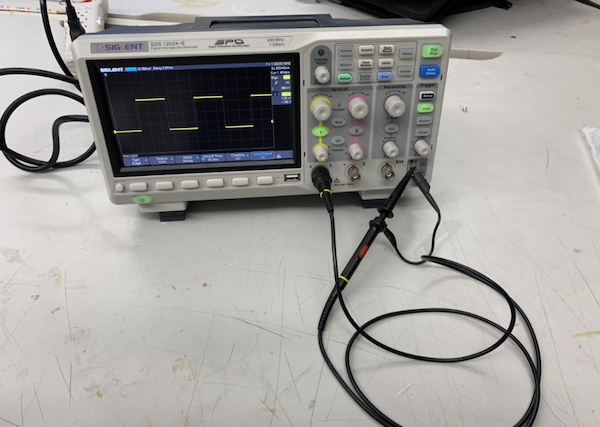
For this week’s group assignment, we had to use the test equipment in your lab to observe the operation of a microcontroller circuit board. I used an oscilloscope to observe the operation of an Arduino Uno 3 while it ran a simple blink program. This week, our groups split up into smaller groups so that we could observe board operations more easily. We started by watching this video. We had never used an oscilloscope before, but this video helped a lot in understanding what to do. I also used this link to understand why oscilloscopes are important. I learned that oscilloscopes are able to measure voltage (seen as values on the Y-axis) in relation to time (seen as values on the X-axis).
The oscilloscope we are using is the SDS1000X-E Series from Siglent. We first turned on the machine. We first turned on the machine and followed the steps in the video to callibrate the oscilloscope and get it ready for testing with the circuit. For callibrating the oscilloscope, did the following: - turning on channel 1 and turning off channel 2 - turning DC to Coupling - making sure the probe was on the 10x setting - under the trigger menu, setting Type -> Edge, Source -> Channel 1, and Slope -> Rising. This was the setup for callibrating the machine.
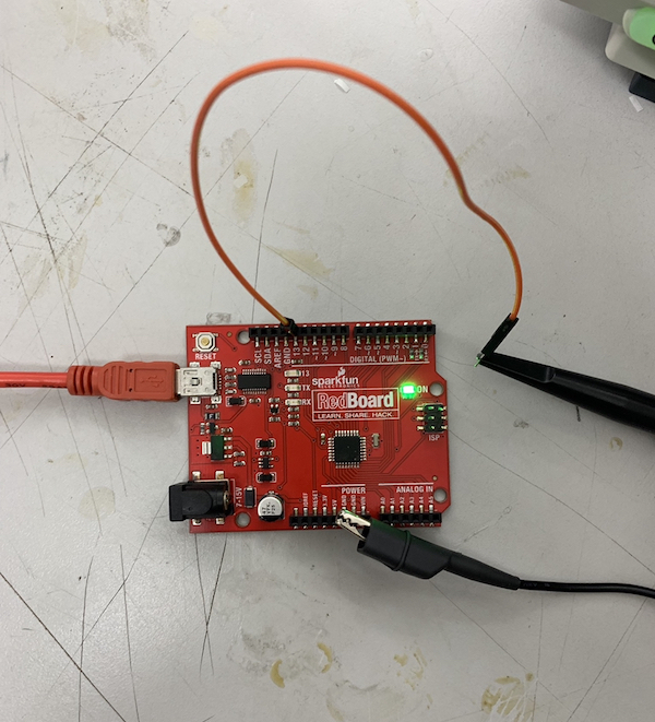
Then we grabbed an Arduino Uno and opened the Arduino program. We uploaded the example simple Blink code to the Arduino and hooked up the Arduino to the oscilloscope, powering the Arduino using a laptop. This was what our setup looked like.
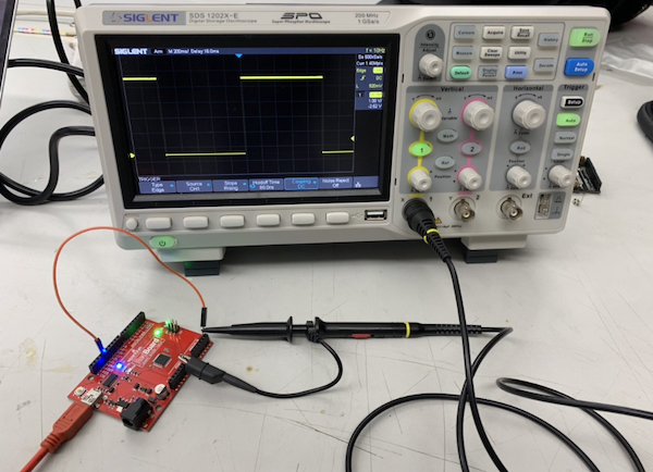
This video shows the voltage reading. We adjusted some different knobs to show the effects of them.
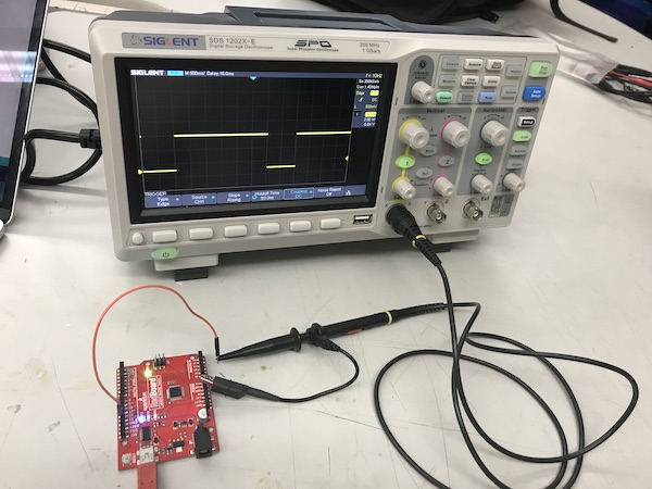
Then to see what the reading of another code would look like, we reuploaded the Blink code after changing the high value to 3000 milliseconds. The reading shows the voltage of the circuit at different times.
Individual Assignment
The individual assignment for this week was to redraw an echo hello-world board, add a button and LED, check the design rules, make it, and test it. I used Autodesk EAGLE to do this.
Getting the Necessary Libraries
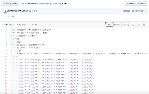
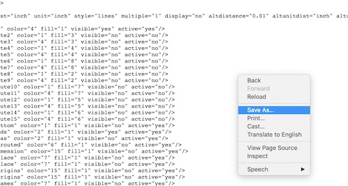
Before I started anything, I downloaded the Eagle FabLab library called fab.lbr and downloaded it from Github. I went to the Raw section to view it, it saved it by right clicking and clicking “save as”.
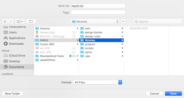
I saved it into the EAGLE libraries folder as an lbr file.
Then I started EAGLE after the library was where it needed to be.
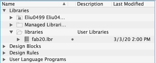
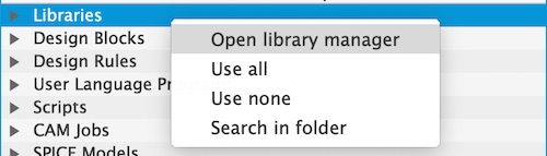
Then I opened the Library Manager by right clicking on Libraries.
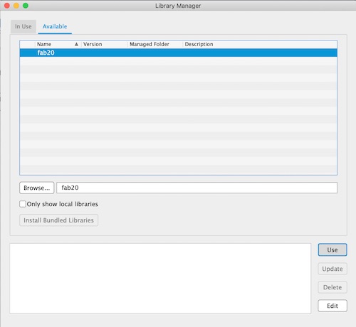
Then, in the Library Manager, I went to the Available section and searched up fab20. I clicked on the library and clicked Use.
I also downloaded a library Mr. Rudolph made for the ATtiny412 called fab_new.lbr and a library called sparkFun-Connectors.lbr from the predownloaded libraries. I went through the same process for the fab20 libraries with this library as well.
Schematic and Traces
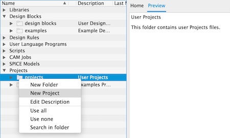
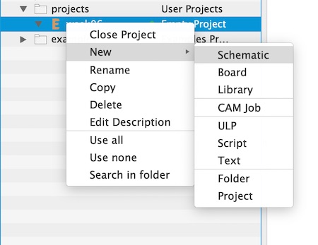
Now it was time to start making the schematic. Once I got to this point, I wanted to learn more about what an echo board is and more about how to use EAGLE. I used this tutorial to help get me started with the program. I read through this website too in order to get comfortable with schematics. I made a new project and renamed it helloWorld. I opened the project and made a new schematic.
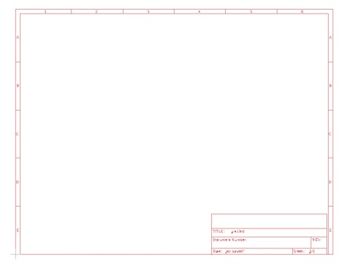
After playing around with EAGLE for a while, I added a letter frame reference while following the tutorial.
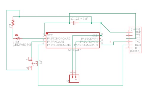
Afterwards, I found the schematic of the echo board using the ATtiny412 chip I needed on the Embedded Programming week website.
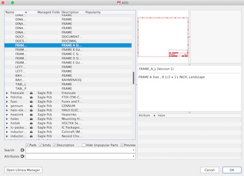
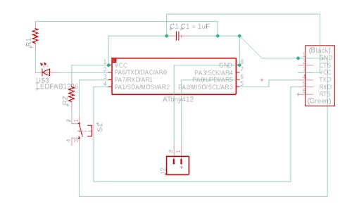
I started adding any components I needed into the schematic. In the search bar, I typed in “add” and hit enter. I started by adding in the ATtiny412 chip.
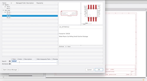
Then I clicked OK and clicked to place the chip where I wanted to. I clicked the esc key and clicked cancel to get rid of the chip from my cursor. The other components I needed included a capacitor, an LED, a resistor, a button, a 6x1 pin header, and a 2x1 pin header. I changed the values of the capacitor and resistor by clicking on the component and pressing Value. Once I had all the parts I needed, I moved them around. After all the components were where I wanted them to be, I used the Net command to connect them.
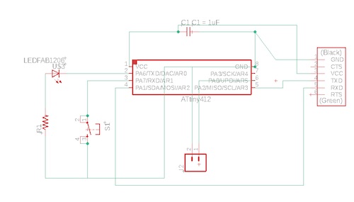
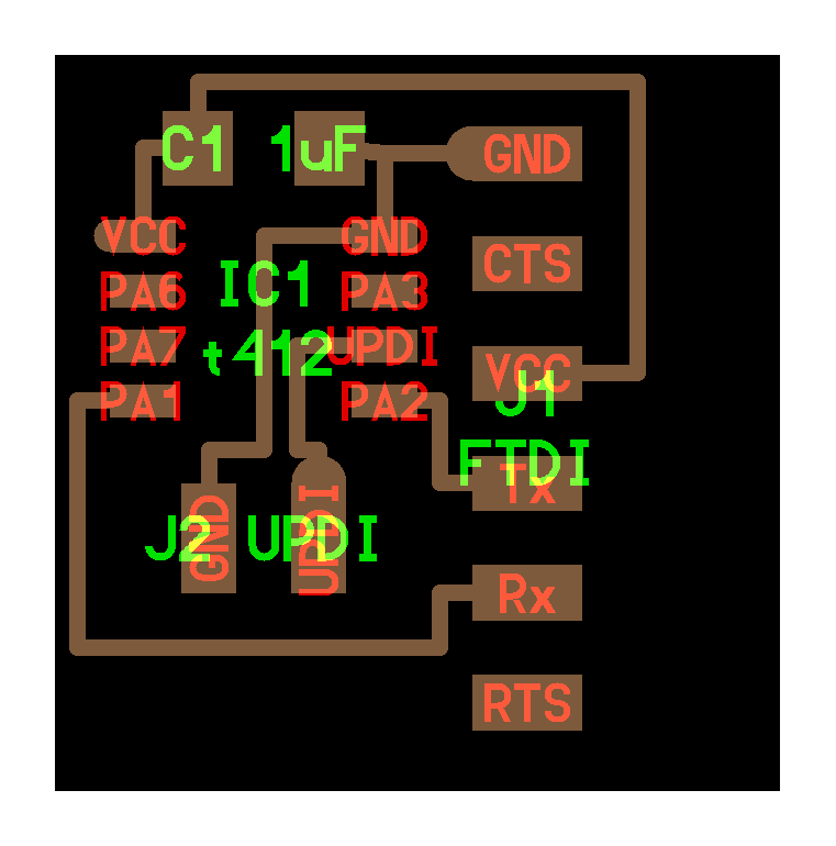
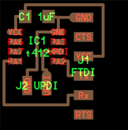
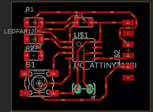
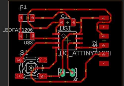
Then I generated the BRD file board to make traces after my schematic was finished. I clicked Generate/switch to board. All the components had been jumbled together in the bottom left corner, so I moved them to where I wanted them to be. It was then time to make the traces. I first tried to use the autorouter after a classmate told me about it. After making sure all my trace widths were 12mm, this is what the autorouted traces looked like and the process I went through to autoroute.
Milling the Board
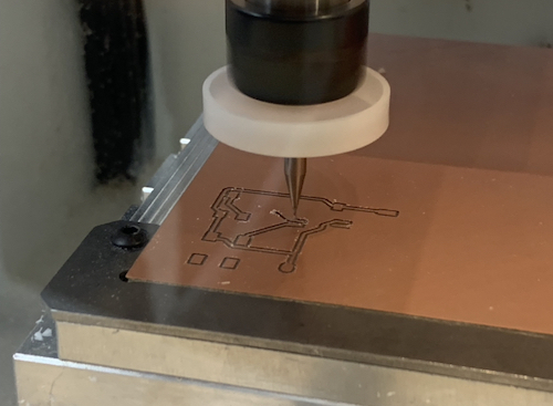
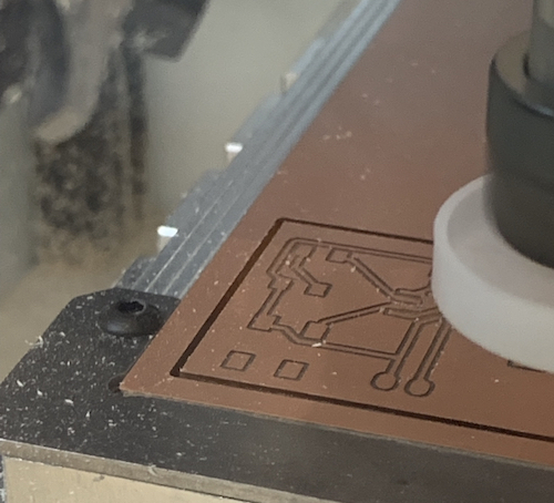
Then after everything seemed to look right, I decided to get it ready for milling. I downloaded Bantam Tools and opened it. This is the process I went through of importing the BRD file, changing the material, and changing the bit size.
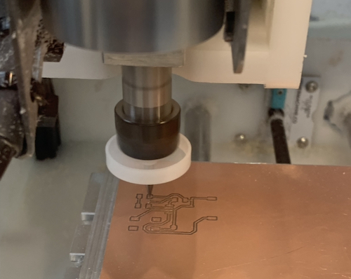
I went through the same process in the computer that was hooked up to our lab’s milling machine. I went through the BitBreaking Probe material thickness process, and clicked Start milling, first for just the traces. Then I changed bits to a 1/32” bit for the outline of the board.
Soldering the Board
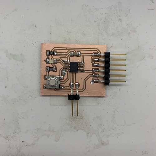
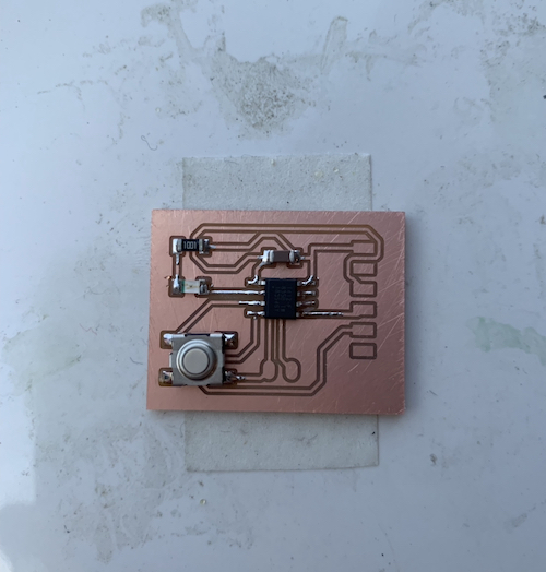
I then soldered parts to the board. I took all the parts I needed: the ATtiny412 chip, a 6x1 connector pin, a 2x1 connector pin, a button, an LED, a 1k Ohm resistor, and a capacitor.
This is where things started to go south a little bit. After I soldered the board, I showed it to Mr. Dubick and the 2x1 pins were almost ripped off from the traces. We used _ to quickly glue the traces back on and everything was alright. However, after testing to program the board using a pre-made programmer, I realized that had soldered my LED backwards. So, I used the __ to remove the LED. However, in the process, I accidentally ripped a trace a tiny bit. To see if the layout and design of the board would work, I soldered the trace together.
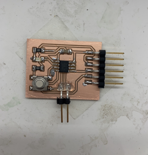
Then I resoldered another LED on correctly and tested the board again.
Unfortunately, the board didn’t work for the following mistakes:
Fixing Some Mistakes
This time, I realized that I hadn’t made a trace between the capacitor and the chip’s ground, nor had I made another set of pad traces for another resistor for the button. Thus, the programer did not work to program the board. I went back to the schematic and added a resistor for the button. I also found out that the wiring of the LED, resistor, and button was wrong, so I fixed it.
Next I went through the process of milling and soldering the board again. This time, I added another 10k Ohm resistor for the button.
I accidentally almost ripped up some traces from the 2x1 pin headers when taking off my board from the tile and Nitto tape, so I upon Mr. Rudolph’s recommendation I used hot glue to glue the pin headers in place.
Then I tried testing my board by programming it from Mr. Rudolph’s computer. I found that it worked well, except for the fact that sometimes the LED would respond to capacitive touch / distance sensing near the copper of the capacitor. After talking with Mr. Rudolph, I decided to remove the resistor of the button, since it might have been causing more ‘noise’ in the circuit.
After I removed the resistor, I tested the board again. I connected the programmer to the board, connecting 5V, GND, and UPDI to each corresponding pin. I uploaded some Blink code to the board, and I found that the board still didn’t work. I decided to put a 0k resistor in its place.
I uploaded some Blink code and found that at first it worked, but when I had to clicked the button, the LED would turn off. Additionally, the button became very hot. The first thing I tried to change was the code– I switched the LOW and HIGH parameters of the methods for the LED so that it would turn on when I clicked the button instead of turn off. The second thing I tried was changing the code to PIN_LIFT (change) allowed the button to not overheat. Then, the button worked! However, the LED was extremely dim when it turned on, and we found it weird that my board would also dim the LED on the programmer. I tried to think of things that might’ve caused the oddity. (Unfortunately, I also forgot to take a video of what was happening.) I tried to take off my button, since it was feeling a little sticky from the heat before, and I replaced it with another one. I was frustrated to find that the entire board no longer worked after I replaced the button. So, it was time to make a new one.
Final Attempt
I first tried to edit the schematic. Since I knew that I no longer needed the resistor for the button, I got rid of it from the schematic.
Then on the board file, I retraced some of the traces leading to the button. I also moved the capacitor a little below the chip so that it gave the traces a little more room to breathe.
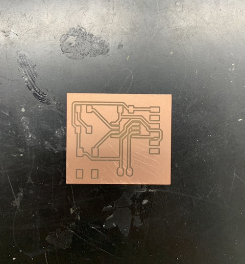
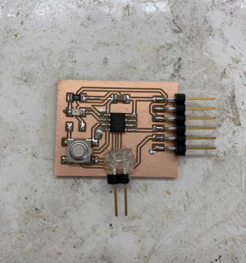
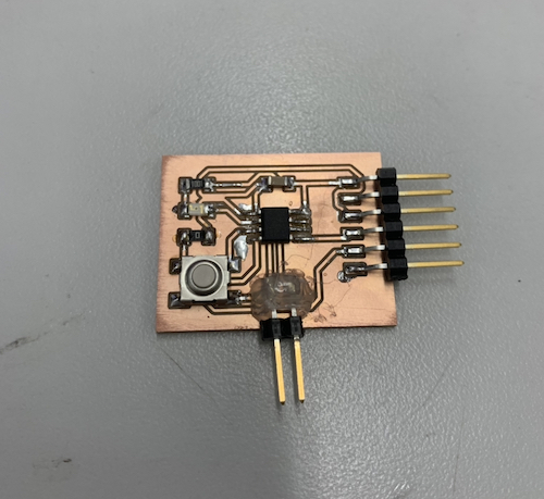
I quickly milled the board, and it came out looking great.
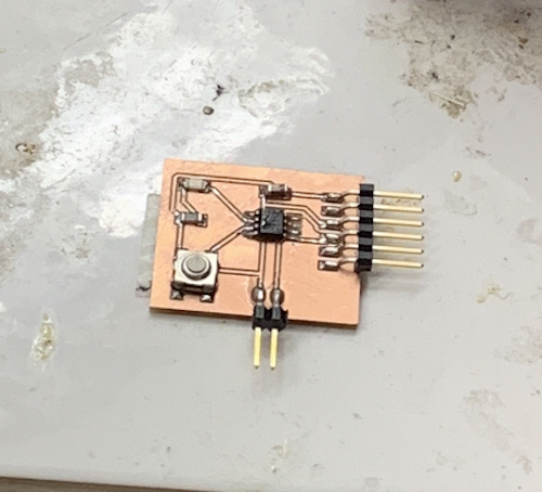
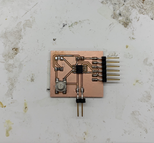
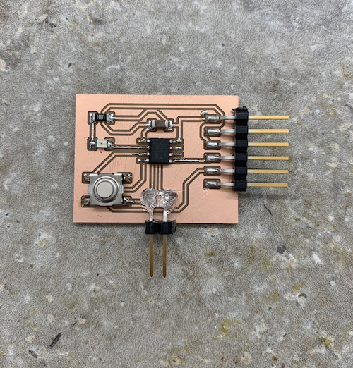
Since I had to leave the lab at this time, I took home with me all the components I needed except for the pin headers, and all the materials I needed to solder everything together. Once I got home, I soldered what I taken home onto my board.
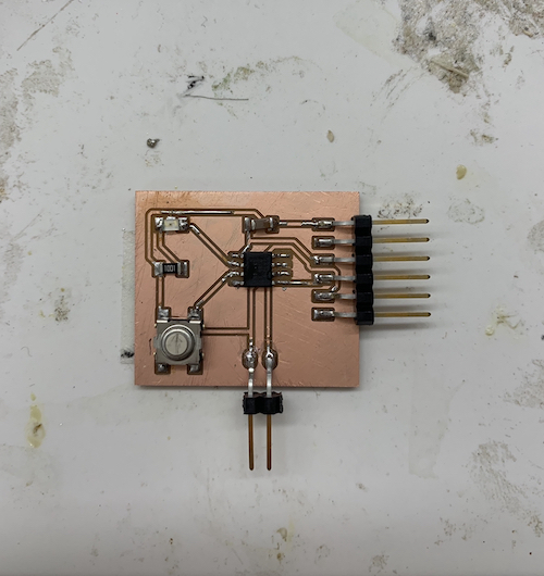
I finished soldering the pins and put some hot glue on them so that they were sturdy.
Blink Test
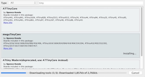
Then it was time to upload some code. I made sure that Arduino had the ATtiny additional board manager link in Preferences. I then went to Board Manager and installed the megaTinyCore boards file (after searching “tiny,” it was the second option).
After I made sure the right board, port, and programmer (jtag2updi (megaTinyCore)) was selected, I used Mr. Rudolph’s blink button code:
#define F_CPU 20000000
#include <avr/delay.h>
#include <avr/io.h>

uint8_t counter;

void setup() {
   PORTA.DIRCLR |= PIN7_bm;           //Set PA7 to input
   PORTA.PIN7CTRL |= PORT_PULLUPEN_bm;  //Set pullup resistor on PA7
   PORTA.DIRSET |= PIN6_bm;           //Set PA6 as output
}

void loop() {
  if(~PORTA.IN & PIN7_bm){  //check to see if PA7 is pulled low
     while(~PORTA.IN & PIN7_bm){ //wait until PA7 returns high
      _delay_ms(5);
      counter++;
      if(counter >= 5){
        PORTA.OUT |= PIN6_bm; //set PA6 LOW
        _delay_ms(1000);
        PORTA.OUT &= ~PIN6_bm; //set PA6 HIGH
      }
     }
  }
}
Finally, the board worked!!
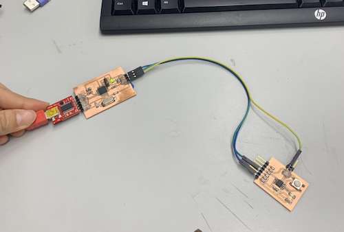
This is what the setup looked like:
Echo Test
In the Serial Monitor, I typed in “hello world” and the board worked as well! In the beginning, it returned empty quotation marks, but it worked the second time.
Board Files
Here are my board files from this week: