8. Embedded programming
This week, I had to compare the performance and development workflows for other architectures for the group project. For the individual project, I had to read a microcontroller data sheet and program my board to do something, with as many different programming languages and programming environments as possible. I had very little knowledge about electronics, so this week was a little rough to get through, but I’m glad I learned as much as I did.
Individual Project
In order to understand some of the basic concepts for this week, I did more searching online after watching Niel’s video. I also searched online and looked at other people from previous years’ documentation. I found clear, laymen’s explanations of such concepts on Sarah Coston’s website that explained it very well. I also looked at this website that broke down the parts of a microcontroller even more clearly. Here is some of the key information:
Hardware: In a microcontroller lies a processor, also called a microprocessor, which is a small chip that receives input and provides an output. A processer only has a CPU inside it (optionally some memory too) while microcontrollers contain the processor in addition to other parts, like the SRAM, called the peripherals. The way the peripherals and processor of a microcontroller are arranged is called architecture. In system development refers to how we hook up the microcontroller to the computer to load code onto it. The Unified Program and Debug Interface (UPDI) is a proprietary interface for external programming and on-chip debugging of a device (379). Software: An integrated development environment, or IDE, is a piece of software that acts as a text editor, debugger, and compiler for code. For example, one IDE is Arduino. Oftentimes we have to upload certain libraries, files written in C or C++, to provide sketches with extra functionality. The code we put into the IDE can range from the most basic assembly language, like a hex file, to the more complicated C, to the highest level Java or Python.
What I learned from the data sheet
I used this tutorial to learn how to read a datasheet first. After looking at the tutorial, I read through the ATtiny412 datasheet, looking for key information described in the tutorial, like the part’s functions and features in the summary, pinout lists, absolute maximum ratings, and recommended operating conditions.
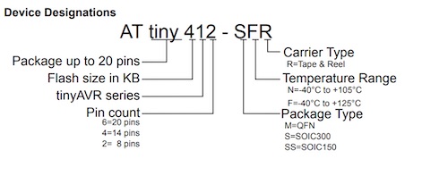
I learned how the ATtiny412 was named:
The ATtiny412’s pinout:
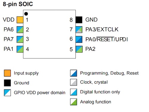
The diagram of the chip was confusing to interpret, but I slowly started to understand it.
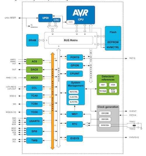
I also learned that the chip used primarily SRAM, EEPROM, and flash memories, as well as information about registers. For example, I learned that the chip uses a Stack and Stack Pointer, using PUSH and POP functions, and that temporary data is stored from higher to lower memory locations.
This datasheet had a vast amount of information– 479 pages worth. It took a long time to scroll through all the pages, but it was worth it. I learned that these tiny chips are so complex and so much more than small black tile; they even have a sleep mode! All of the information on the data sheet is important, but I chose to explain the content that I think was most important to understanding the foundation level information in this week.
Programming my Board
This week, I used my board from week 6 (Echo Board) and programmed it. However, since we couldn’t have access to our lab because of coronavirus, I used a premade jtag2updi programmer that Mr. Rudolph made from week 6. However, this programmer didn’t have a resistor between the two UPDI pins, so I needed a 4.7k Ohm resistor. Luckily, I brought home my other boards that didn’t work from before, as well as my old FabtinyISP I made from week 4. Collectively, there were 4x1k Ohm resistors that I could use. I realized that if I soldered them together, they’d add up to be 4k Ohms, which is close enough for the purpose of this week. I unsoldered the resistors from each board, and soldered them together, forming a strip of resistors. Then I soldered the strip to two male ends of male-female wires.
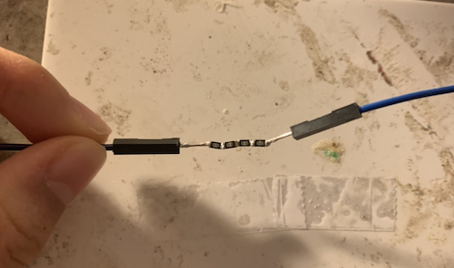
Although it looked janky, it served its purpose well for this week.
Arduino IDE
I decided that for my board, I would program it to turn on an LED when the button is pressed. I first started in Arduino. I used the Digital Button example Arduino C code. I wanted to also learn and understand how C bitshifting worked. In order to better understand how C works, I looked at this brief tutorial on C assignment operators.
| Operator | Description | Example |
|---|---|---|
| <<= | Left shift AND assignment operator | C <<= 2 is same as C = C << 2 |
| >>= | Right shift AND assignment operator | C >>= 2 is same as C = C >> 2 |
| &= | Bitwise AND assignment operator | C &= 2 is same as C = C & 2 |
| ^= | Bitwise exclusive OR and assignment operator | C ^= 2 is same as C = C ^ 2 |
| I= | Bitwise inclusive OR and assignment operator | C I= 2 is same as C = C I 2 |
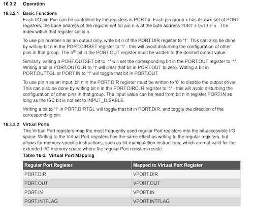
I also referenced the datasheet for the ATtiny412 to see how to change pin and port references. In order to declare which ports are the input or output, we change the value of PORT.DIR using bitwise operations on PORT.DIRSET and PORT.DIRCLR. The value of ports will be set with a bitwise operation on the virtual port register, VPORT.OUT.
I started off referencing the logic of the original button code, but I changed the syntax of how things were written.
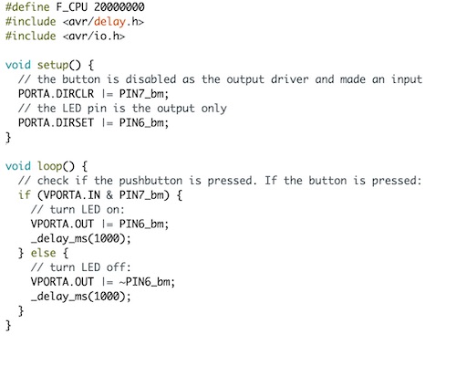
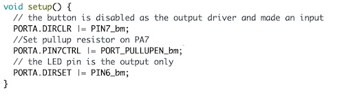
I looked at week 6’s code to reference how to set the pullup resistor on the output pin.
#define F_CPU 20000000
#include <avr/delay.h>
#include <avr/io.h>

void setup() {
  // the button is disabled as the output driver and made an input
  PORTA.DIRCLR |= PIN7_bm;
  //Set pullup resistor on PA7
  PORTA.PIN7CTRL |= PORT_PULLUPEN_bm;
  // the LED pin is the output only
  PORTA.DIRSET |= PIN6_bm;
}

void loop() {
  // check if the pushbutton is pressed. If the button is pressed:
  if (VPORTA.IN & PIN7_bm) {
    // turn LED on:
    VPORTA.OUT |= PIN6_bm;
    _delay_ms(1000);
  }
  else {
    // turn LED off:
    VPORTA.OUT |= ~PIN6_bm;
    _delay_ms(1000);
  }
}
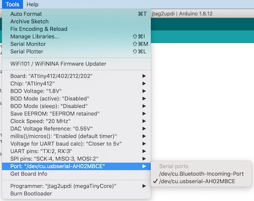
Then I made sure all the details were in check– the correct board, port, and programmer.
However, when I programmed the board, it didn’t work the way I wanted it to. I realized that the logic behind my code was incorrect. I referenced back to week 6’s code written by Mr. Rudolph, and everything made much more sense. I had to add a while loop and put the blinking action under the nested while loop in the if statement. This is what the code looked like:
#define F_CPU 20000000
#include <avr/delay.h>
#include <avr/io.h>

uint8_t counter;

void setup() {
   //Set PA7 to input
   PORTA.DIRCLR |= PIN7_bm;
   //Set pullup resistor on PA7
   PORTA.PIN7CTRL |= PORT_PULLUPEN_bm;
   //Set PA6 as output
   PORTA.DIRSET |= PIN6_bm;
}

void loop() {
  //check to see if PA7 is pulled low
  if(~PORTA.IN & PIN7_bm){
     //wait until PA7 returns high
     while(~PORTA.IN & PIN7_bm){
      _delay_ms(5);
      counter++;
      if(counter >= 5){
        //set PA6 to LOW
        PORTA.OUT |= PIN6_bm;
        _delay_ms(1000);
        //set PA6 to HIGH
        PORTA.OUT &= ~PIN6_bm;
      }
     }
  }
}
Then I reuploaded the code, and it worked! I think it didn’t work before because the if else statement I used didn’t properly account for the time it would take to recognize the button value. But here is the video of the board working!:
Atmel Studio IDE
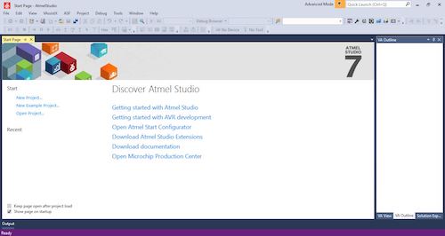
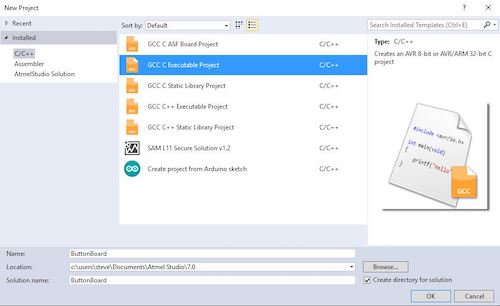
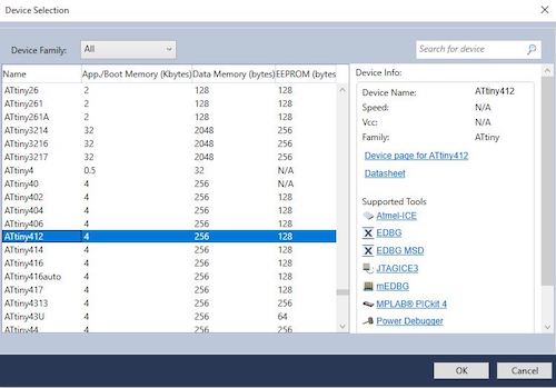
I tried to use Atmel Studio to code my board using C bitshifting too. I first downloaded Atmel Studio on another computer that used the Windows operating system at home, since I couldn’t download it on Mac. It took a long, long time to download Atmel, but after it finished downloading, I tried to play around in the IDE. I opened up Atmel to the start screen. I made a new project, selected my board as the ATtiny412, and started inserting the code I used for the Arduino IDE with C bitshifting.
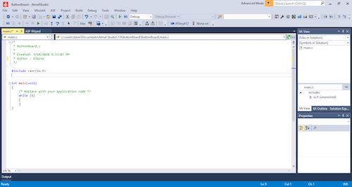
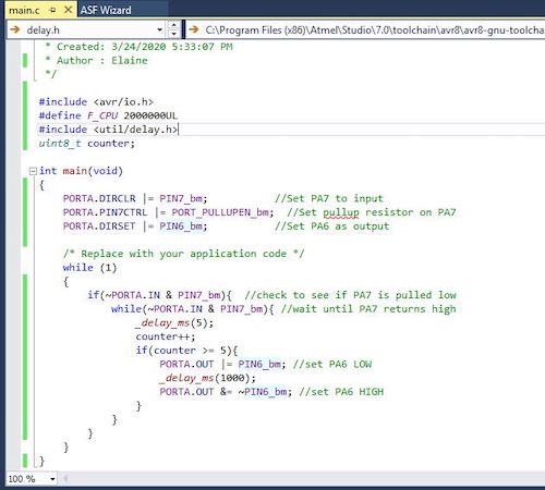
I noticed that there wasn’t a void setup() method or a void loop() method, but rather an int main(void) method, similar to what I am familiar with in Java. I also noticed that there was a while loop. I figured that the code before the while loop is for any declarations or instantiations, and that the code in the while loop is the code that would usually go into the void loop() method.
I organized the working code that I used in the Arduino IDE, and added the two lines:
#define F_CPU 2000000UL
#include <util/delay.h>
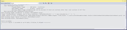
I was confused as to how I should compile the code, since I didn’t see any button that explicity said compile. After watching this video/walkthrough on how to upload code to a microcontroller, I found that Build > Build Solution was the “compile” equivalent. I clicked it, and I got no errors.
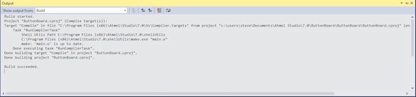
Afterwards, I realized there was a compile button under Build > Compile, so I compiled the code again, and I got no errors.
Then I navigated to the avrdude.exe file that Arduino uses. This was in
C:\Users\steve\AppData\Local\Arduino15\packages\arduino\tools\avrdude\6.3.0-arduino17\bin\avrdude.exe
I also navigated to the avrdude.conf file that came with the megaTinyCore board manager. This was in
C:\Users\steve\AppData\Local\Arduino15\packages\megaTinyCore\hardware\megaavr\1.1.8\avrdude.conf
Then I opened up Tools > External Tools… In the Command box, I pasted the path of the avrdude.exe file from above. In the Arguments box, I entered the following text, with a space instead of an enter between each line:
-P com9                                            # The port your jtag2updi is plugged in
-C (PATH)                                          # The path of your avrdude.conf file
-c jtag2updi                                       # The programmer you are using
-p t412                                            # The chip you are trying to program
-U flash:w:$(ProjectDir)Debug/$(TargetName).hex:i  # Memory operation specification (Don't Change)
It looked like:
-P com9 -C C:\Users\steve\AppData\Local\Arduino15\packages\megaTinyCore\hardware\megaavr\1.1.8\avrdude.conf -c jtag2updi -p t412 -U flash:w:$(ProjectDir)Debug\$(TargetName).hex:i
I also renamed the Title to jtag2updi attiny412.
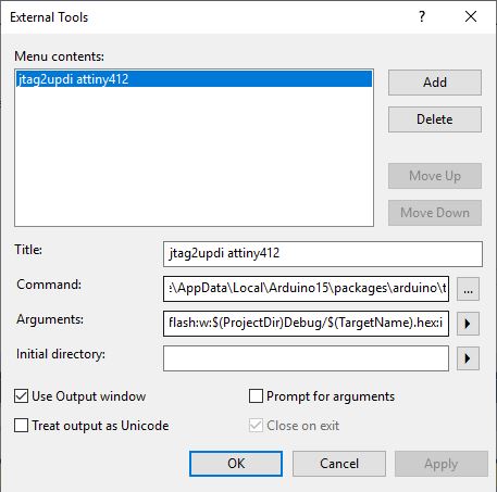
Then I checked Output Window I clicked Apply then OK. Then I clicked Tools > jtag2updi attiny412 and my board was programmed.
Files
Here are my files for this week:
Group Project
Here is the link for our group project this week.