12. Output devices
This week’s assignment:
group assignment:
measure the power consumption of an output device
individual assignment:
add an output device to a microcontroller board you’ve designed, and program it to do something
Measuring power consumption
We decided to measure the draw of an LED.
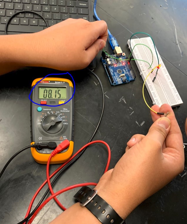
We connected the LED and a resistor to an Arduino and turned on the light. With a multimeter, we found that the LED drew just above 8 mA.
Photo credit: Will Knight
Designing an output board
This week, in continuing my preparation for the final project, I decided to work on using LCDs. I designed my board following Neil’s example, found here.
![]()
I tried to add a row of female pin headers onto the board so I could directly attach an LCD to the board, but I encountered clearance issues (as seen above) when I tried to cleanly route the necessary traces. Instead, I kept the original design and used jumper wires and a breadboard for this assignment.
Building the board
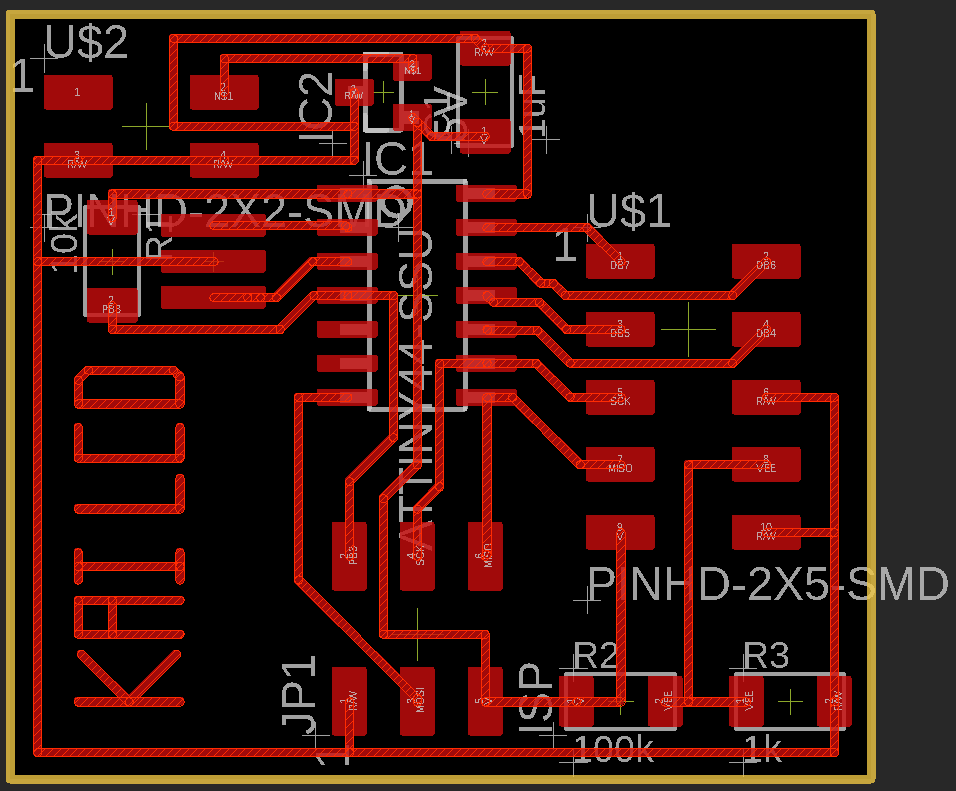
Above, my finished board file. Once I finished designing the board in EAGLE, I milled it with a 1/64” bit on our Othermill without any issues and soldered the components on.
Testing the board
In the above video, you can see the LCD board functioning with the Hello World code found here.
I added a line to define the clock rate on my board (20 MHz). The full code I used is as follows:
//
// hello.LCD.44.c
//
// LCD hello-world
//
// set lfuse to 0x5E for 20 MHz xtal
//
// Neil Gershenfeld
// 11/14/10
//
// (c) Massachusetts Institute of Technology 2010
// This work may be reproduced, modified, distributed,
// performed, and displayed for any purpose. Copyright is
// retained and must be preserved. The work is provided
// as is; no warranty is provided, and users accept all
// liability.
//

#define F_CPU 20000000

#include <avr/io.h>
#include <util/delay.h>
#include <avr/pgmspace.h>

#define output(directions,pin) (directions |= pin) // set port direction for output
#define set(port,pin) (port |= pin) // set port pin
#define clear(port,pin) (port &= (~pin)) // clear port pin
#define pin_test(pins,pin) (pins & pin) // test for port pin
#define bit_test(byte,bit) (byte & (1 << bit)) // test for bit set

#define LCD_port PORTA
#define LCD_direction DDRA
#define DB7 (1 << PA0)
#define DB6 (1 << PA1)
#define DB5 (1 << PA2)
#define DB4 (1 << PA3)
#define E (1 << PA4)
#define RS (1 << PA5)

#define long_delay() _delay_ms(1000) // delay before redraw
#define lcd_delay() _delay_ms(10) // delay between commands
#define strobe_delay() _delay_us(1) // delay for strobe

//
// lcd_putchar
//    put character in lcdbyte
//
void lcd_putchar(char lcdbyte) {
   //
   // set RS for data
   //
   set(LCD_port, RS);
   //
   // output high nibble
   //
   if bit_test(lcdbyte, 7)
      set(LCD_port, DB7);
   else
      clear(LCD_port, DB7);
   if bit_test(lcdbyte, 6)
      set(LCD_port, DB6);
   else
      clear(LCD_port, DB6);
   if bit_test(lcdbyte, 5)
      set(LCD_port, DB5);
   else
      clear(LCD_port, DB5);
   if bit_test(lcdbyte, 4)
      set(LCD_port, DB4);
   else
      clear(LCD_port, DB4);
   //
   // strobe E
   //
   strobe_delay();
   set(LCD_port, E);
   strobe_delay();
   clear(LCD_port, E);
   //
   // wait
   //
   lcd_delay();
   //
   // output low nibble
   //
   if bit_test(lcdbyte, 3)
      set(LCD_port, DB7);
   else
      clear(LCD_port, DB7);
   if bit_test(lcdbyte, 2)
      set(LCD_port, DB6);
   else
      clear(LCD_port, DB6);
   if bit_test(lcdbyte, 1)
      set(LCD_port, DB5);
   else
      clear(LCD_port, DB5);
   if bit_test(lcdbyte, 0)
      set(LCD_port, DB4);
   else
      clear(LCD_port, DB4);
   //
   // strobe E
   //
   strobe_delay();
   set(LCD_port, E);
   strobe_delay();
   clear(LCD_port, E);
   //
   // wait and return
   //
   lcd_delay();
   }
//
// lcd_putcmd
//    put command in lcdbyte
//
void lcd_putcmd(char lcdbyte) {
   //
   // clear RS for command
   //
   clear(LCD_port, RS);
   //
   // output command bits
   //
   PORTA = lcdbyte;
   //
   // strobe E
   //
   strobe_delay();
   set(LCD_port, E);
   strobe_delay();
   clear(LCD_port, E);
   //
   // wait and return
   //
   lcd_delay();
   }
//
// lcd_putstring
//    put a null-terminated string in flash
//
void lcd_putstring(PGM_P message) {
   static uint8_t index;
   static char chr;
   index = 0;
   while (1) {
      chr = pgm_read_byte(&(message[index]));
      if (chr == 0)
         return;
      lcd_putchar(chr);
      ++index;
      }
   }
//
// lcd_init
//    initialize the LCD
//
void lcd_init() {
   //
   // power-up delay
   //
   lcd_delay();
   //
   // initialization sequence
   //
   lcd_putcmd(DB5+DB4);
   lcd_putcmd(DB5+DB4);
   lcd_putcmd(DB5+DB4);
   //
   // 4-bit interface
   //
   lcd_putcmd(DB5);
   //
   // two lines, 5x7 font
   //
   lcd_putcmd(DB5);
   lcd_putcmd(DB7);
   //
   // display on
   //
   lcd_putcmd(0);
   lcd_putcmd(DB7+DB6+DB5);
   //
   // entry mode
   //
   lcd_putcmd(0);
   lcd_putcmd(DB6+DB5);
   }

int main(void) {
   //
   // main
   //
   // set clock divider to /1
   //
   CLKPR = (1 << CLKPCE);
   CLKPR = (0 << CLKPS3) | (0 << CLKPS2) | (0 << CLKPS1) | (0 << CLKPS0);
   //
   // initialize LCD pins
   //
   clear(LCD_port, DB7);
   output(LCD_direction, DB7);
   clear(LCD_port, DB6);
   output(LCD_direction, DB6);
   clear(LCD_port, DB5);
   output(LCD_direction, DB5);
   clear(LCD_port, DB4);
   output(LCD_direction, DB4);
   clear(LCD_port, E);
   output(LCD_direction, E);
   clear(LCD_port, RS);
   output(LCD_direction, RS);
   //
   // initialize LCD
   //
   lcd_init();
   //
   // main loop
   //
   while (1) {
      //
      // go to zero position
      //
      lcd_putcmd(0);
      lcd_putcmd(DB5);
      //
      // print first line from flash
      //
      static const char line1[] PROGMEM = "Hello to";
      lcd_putstring((PGM_P) line1);
      //
      // move to second line
      //
      lcd_putcmd(DB7+DB6);
      lcd_putcmd(0);
      //
      // print second line from flash
      //
      static const char line2[] PROGMEM = "the world";
      lcd_putstring((PGM_P) line2);
      //
      // pause
      //
      long_delay();
      //
      // clear display
      //
      lcd_putcmd(0);
      lcd_putcmd(DB4);
      }
   }
Making the board do something fancy!
Once I had the Hello World code working, I wanted to play with a fun way to display information: autoscroll. I discovered this in the Examples in Arduino IDE. I had to take a while to review the pinouts of both my board and the LCD.

Above, you can see the helpful LCD pinout that I found here. I also found the datasheet for my LCD here.

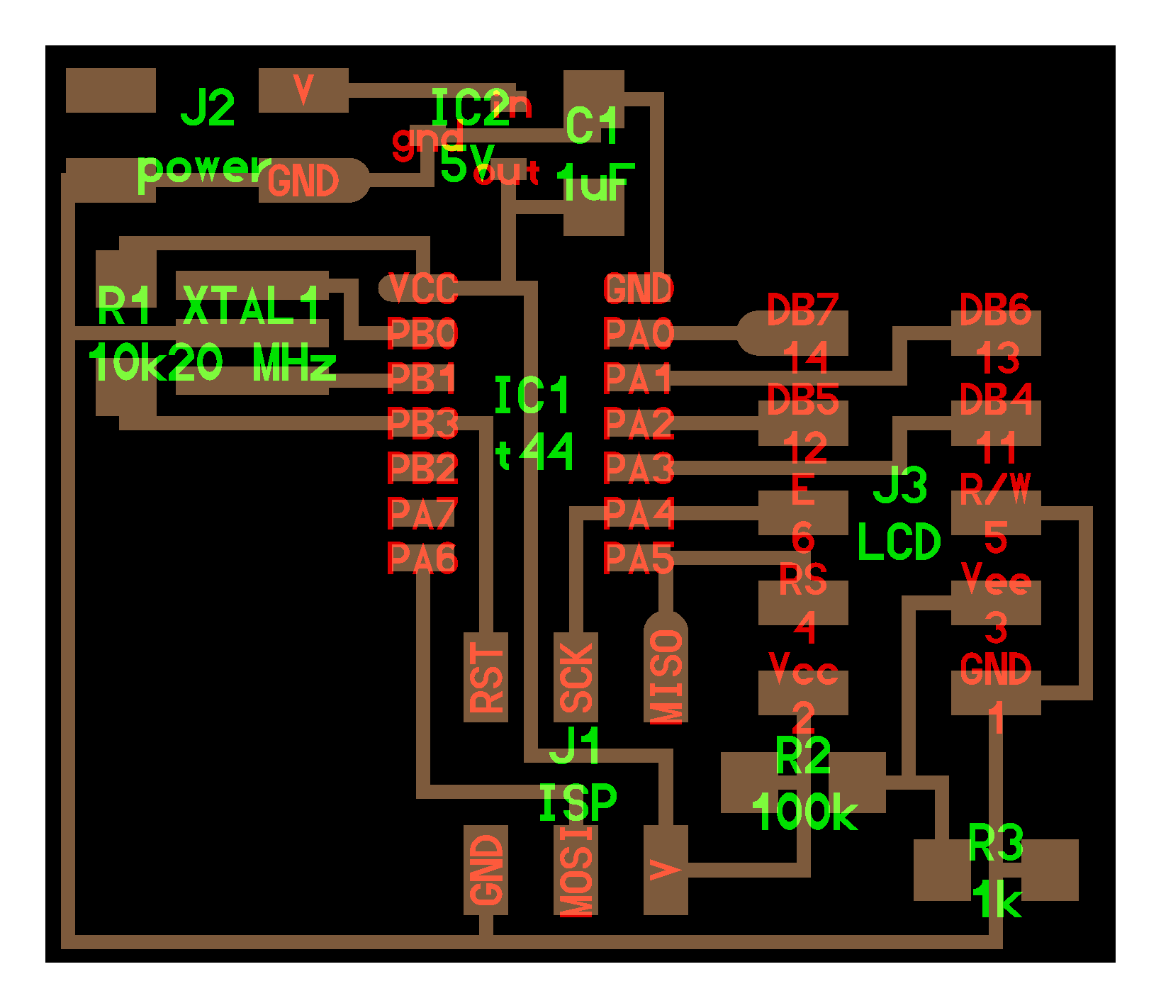
Above, you can see my EAGLE schematic for my LCD board.
// ATMEL ATTINY84 / ARDUINO
//
//                           +-\/-+
//                     VCC  1|    |14  GND
//             (D 10)  PB0  2|    |13  AREF (D  0)
//             (D  9)  PB1  3|    |12  PA1  (D  1)
//                     PB3  4|    |11  PA2  (D  2)
//  PWM  INT0  (D  8)  PB2  5|    |10  PA3  (D  3)
//  PWM        (D  7)  PA7  6|    |9   PA4  (D  4)
//  PWM        (D  6)  PA6  7|    |8   PA5  (D  5)        PWM
//                           +----+
Finally, you can see above a pinout for the ATTiny, which I found here at the source of the ATTiny library I am using with the Arduino IDE. Note that various pinouts online are based on different libraries and programs, so be sure to find the correct pinout for your application.
Using these resources, I determined the correct Arduino pin numbers for the LCD pins and subsequently made the respective changes to the autoscroll example. My code is as follows:
/*
  LiquidCrystal Library - Autoscroll

 Demonstrates the use a 16x2 LCD display.  The LiquidCrystal
 library works with all LCD displays that are compatible with the
 Hitachi HD44780 driver. There are many of them out there, and you
 can usually tell them by the 16-pin interface.

 This sketch demonstrates the use of the autoscroll()
 and noAutoscroll() functions to make new text scroll or not.

 The circuit:
 * LCD RS pin to digital pin 12
 * LCD Enable pin to digital pin 11
 * LCD D4 pin to digital pin 5
 * LCD D5 pin to digital pin 4
 * LCD D6 pin to digital pin 3
 * LCD D7 pin to digital pin 2
 * LCD R/W pin to ground
 * 10K resistor:
 * ends to +5V and ground
 * wiper to LCD VO pin (pin 3)

 Library originally added 18 Apr 2008
 by David A. Mellis
 library modified 5 Jul 2009
 by Limor Fried (http://www.ladyada.net)
 example added 9 Jul 2009
 by Tom Igoe
 modified 22 Nov 2010
 by Tom Igoe
 modified 7 Nov 2016
 by Arturo Guadalupi

 This example code is in the public domain.

 http://www.arduino.cc/en/Tutorial/LiquidCrystalAutoscroll

*/

// include the library code:
#include <LiquidCrystal.h>

// initialize the library by associating any needed LCD interface pin
// with the arduino pin number it is connected to
const int rs = 5, en = 4, d4 = 3, d5 = 2, d6 = 1, d7 = 0;
LiquidCrystal lcd(rs, en, d4, d5, d6, d7);

void setup() {
  // set up the LCD's number of columns and rows:
  lcd.begin(16, 2);
}

void loop() {
  // set the cursor to (0,0):
  lcd.setCursor(0, 0);
  // print from 0 to 9:
  for (int thisChar = 0; thisChar < 10; thisChar++) {
    lcd.print(thisChar);
    delay(500);
  }

  // set the cursor to (16,1):
  lcd.setCursor(16, 1);
  // set the display to automatically scroll:
  lcd.autoscroll();
  // print from 0 to 9:
  for (int thisChar = 0; thisChar < 10; thisChar++) {
    lcd.print(thisChar);
    delay(500);
  }
  // turn off automatic scrolling
  lcd.noAutoscroll();

  // clear screen for the next loop:
  lcd.clear();
}
You can see the code working in the above video.
Moving beyond the assignment
After I got Autoscroll working, I worked on integrating the inputs board from Week 11 by displaying the temperature information from the serial output of the inputs board on my LCD. I began with the example Serial Display sketch in the Arduino IDE and changed the standard Serial parts to Software Serial (I consulted the Arduino documentation for the Software Serial library here) because the Tiny 44 doesn’t have standard UART TX/RX pins like the Mega 328 on my inputs board does. I chose the two unused pins on my Tiny 44, 8 & 7, for RX & TX, respectively. I only needed an RX, so I soldered a jumper wire to that pin on the LCD Board so that I could connect to the TX pin on my inputs board. My code was as follows:
/*
  LiquidCrystal Library - Serial Input

 Demonstrates the use a 16x2 LCD display.  The LiquidCrystal
 library works with all LCD displays that are compatible with the
 Hitachi HD44780 driver. There are many of them out there, and you
 can usually tell them by the 16-pin interface.

 This sketch displays text sent over the serial port
 (e.g. from the Serial Monitor) on an attached LCD.

 The circuit:
 * LCD RS pin to digital pin 12
 * LCD Enable pin to digital pin 11
 * LCD D4 pin to digital pin 5
 * LCD D5 pin to digital pin 4
 * LCD D6 pin to digital pin 3
 * LCD D7 pin to digital pin 2
 * LCD R/W pin to ground
 * 10K resistor:
 * ends to +5V and ground
 * wiper to LCD VO pin (pin 3)

 Library originally added 18 Apr 2008
 by David A. Mellis
 library modified 5 Jul 2009
 by Limor Fried (http://www.ladyada.net)
 example added 9 Jul 2009
 by Tom Igoe
 modified 22 Nov 2010
 by Tom Igoe
 modified 7 Nov 2016
 by Arturo Guadalupi

 This example code is in the public domain.

 http://www.arduino.cc/en/Tutorial/LiquidCrystalSerialDisplay

*/

// include the library code:
#include <LiquidCrystal.h>

// initialize the library by associating any needed LCD interface pin
// with the arduino pin number it is connected to
const int rs = 5, en = 4, d4 = 3, d5 = 2, d6 = 1, d7 = 0, RX = 7, TX = 8;
LiquidCrystal lcd(rs, en, d4, d5, d6, d7);

#include <SoftwareSerial.h>
// ***
// *** Define the RX and TX pins. Choose any two
// *** pins that are unused. Try to avoid D0 (pin 5)
// *** and D2 (pin 7) if you plan to use I2C.
// ***
// int RX = 8;   // *** D3, Pin 2
//#define TX    8   // *** D4, Pin 3

// ***
// *** Define the software based serial port. Using the
// *** name Serial so that code can be used on other
// *** platforms that support hardware based serial. On
// *** chips that support the hardware serial, just
// *** comment this line.
// ***
SoftwareSerial mySerial (RX, TX);

void setup() {
  // set up the LCD's number of columns and rows:
  lcd.begin(16, 2);
  // initialize the serial communications:
  mySerial.begin(9600);
}

void loop() {
  // when characters arrive over the serial port...
  if (mySerial.available()) {
    // Serial.write(mySerial.read());
    // wait a bit for the entire message to arrive
    delay(100);
    // clear the screen
    lcd.clear();
    // read all the available characters
    while (mySerial.available() > 0) {
      // display each character to the LCD
      lcd.write(mySerial.read());
    }
  }
}
I tried fiddling with code to move extra characters to the second line of the screen (shoutout to this Arduino forum post for great working code), but it didn’t look great and I instead shortened the original serial output on the Satshakit so that it would fit on one line. My updated Satshakit code is as follows:
int sensorPin = 0;

void setup() {
  // put your setup code here, to run once:
  Serial.begin(9600);
}

void loop() {
  // put your main code here, to run repeatedly:
  int reading = analogRead(sensorPin);
  float voltage = reading * (5.0 / 1024.0) ;
  float tempC = (voltage - 0.5) * 100 ;
  float tempF = (tempC * 9.0 / 5.0) + 32.0 ;
  Serial.println("It is "); Serial.print(tempF); Serial.println(" F");
  delay(1000);
}
Note: I again encountered issues with uploading code to my Satshakit via FTDI. For some reason, it appears that my board will not reset via the FTDI to allow the new code to be uploaded, so I had to connect the board to my FabTinyISP programmer and burn the bootloader and upload the code that way. I suppose the issue would be resolved if I made a new board, but I am uncertain. Anyhow, uploading via a programmer worked fine.
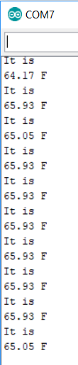
The updated serial output appeared as seen above in the Arduino IDE Serial Monitor.
You can see the display functioning in the above two videos. I used this to satisfy the group assignment for week 14.

Special thanks to Maxine for her expertise and assistance with the Software Serial library and her steady soldering hand as I remade the LCD board.
My LCD Board Files (BOM, .brd, .sch, .btm, .ino files in .zip folder)