7. Electronics design
This week’s assignment:
group assignment:
use the test equipment in your lab to observe the operation of a microcontroller circuit board
individual assignment:
redraw the echo hello-world board
add (at least) a button and LED (with current-limiting resistor)
check the design rules, make it, and test it
extra credit: simulate its operation
extra credit: render it
Using an Oscilloscope
Our Lab has a SIGLENT SDS1000X-E Series Super Phosphor Oscilloscope.
To begin, I watched this Sparkfun tutorial on YouTube per the recommendation of my instructors. The short video gave me a good understanding of the basic features of an oscilloscope.
Next, I took a look at the user manual, which was located on an included CD-ROM. I susbsequently discovered that there was software compatible with our oscilloscope called EasyScopeX. The software was on the CD-ROM, but I had to install additional drivers from National Instruments. With this software, I could take screen recordings of the oscilloscope or control it remotely.
Once we were ready to begin using the scope, we had to calibrate it per the instructions in the aforementioned tutorial video.
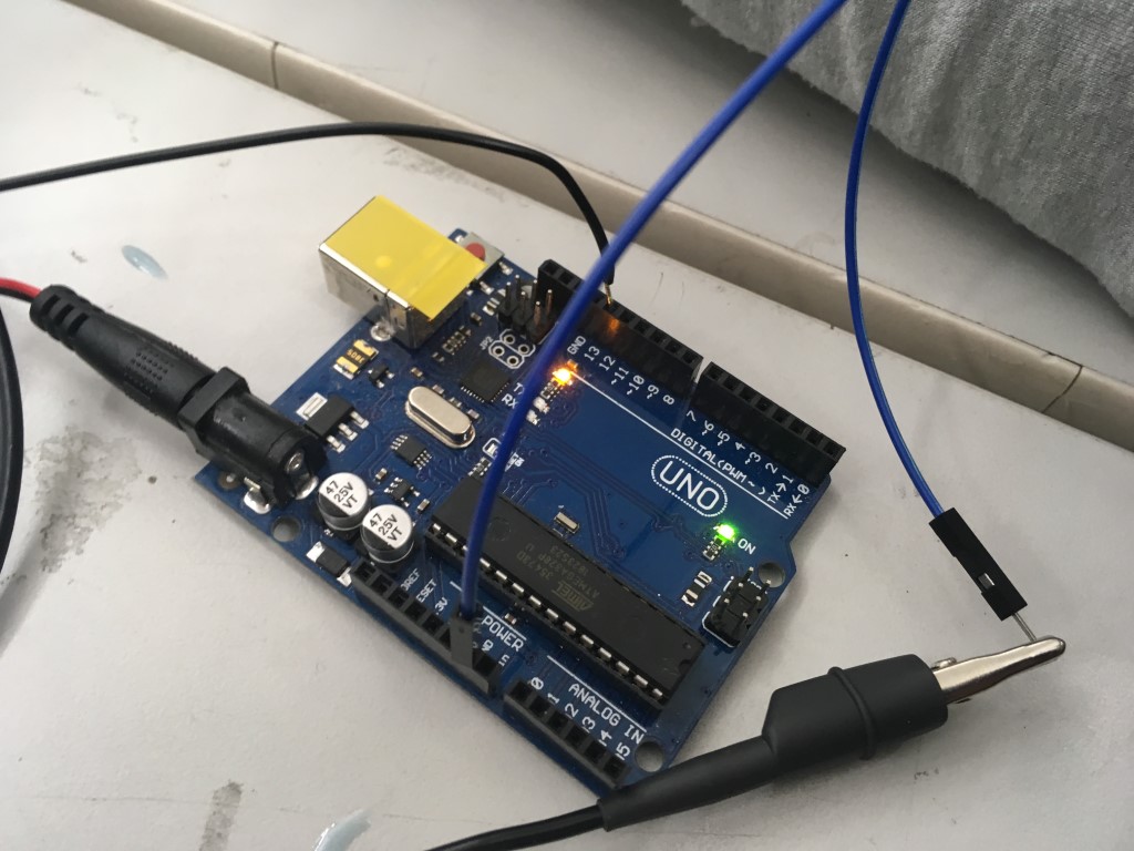
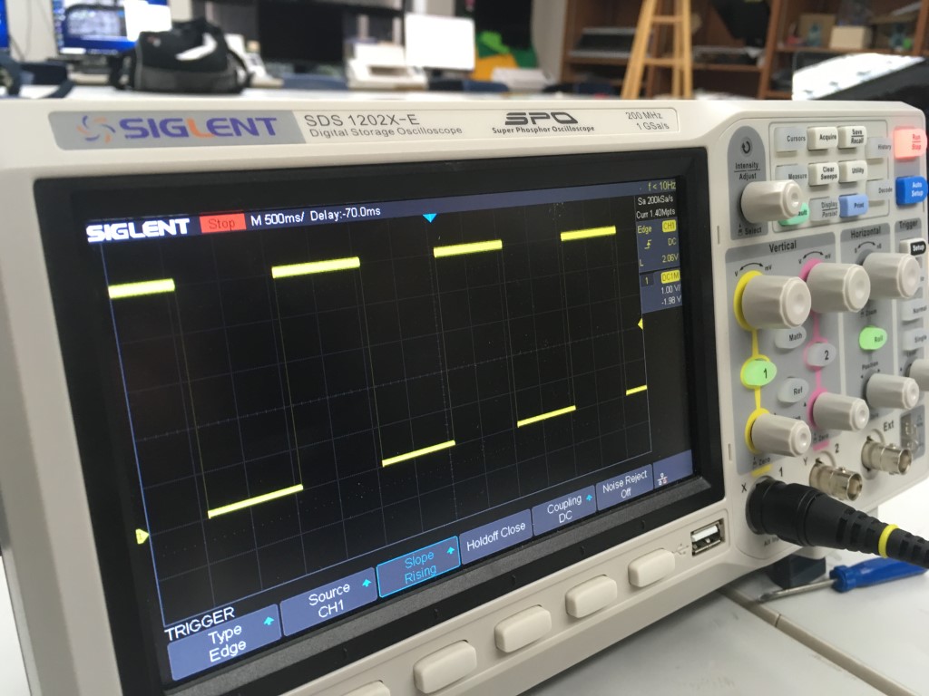
After calibrating the scope, we decided to test the function of a basic Blink code with an Arduino. Sure enough, the High and Low signals came across the screen as the LED flashed on and off.
We also modified the sample Blink code to have varying blink lengths, and these showed up correspondingly on the oscilloscope’s screen.
Redrawing the Hello-World board
I downloaded EAGLE with my student license here.
In order to have more of the parts we use in our Fab Lab available in EAGLE, I downloaded the Fab library for EAGLE here and copied it to EAGLE’s Library folder (C:\Users\LENOVO USER\Documents\EAGLE\libraries on my laptop). (.zip folder of library)
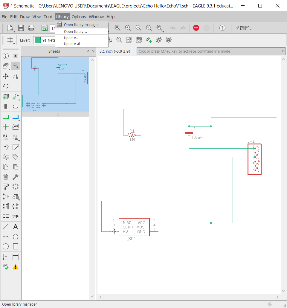
Then I opened EAGLE and opened a schematic file, clicked Library > Open Library Manager…
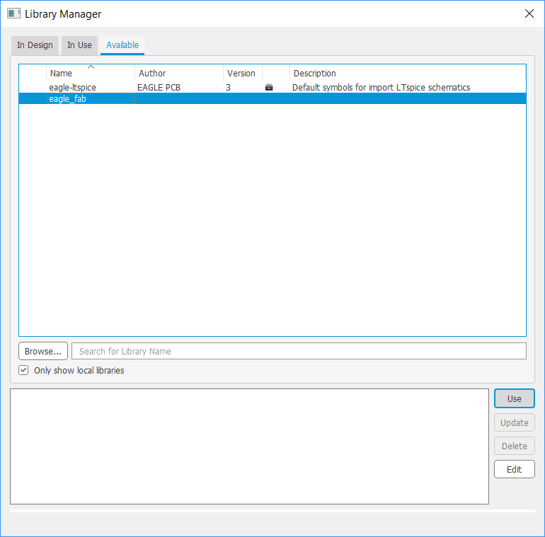
…clicked Available, selected eagle_fab (the name of the Fab library I downloaded), and clicked Use.
I also added the Adafruit and Sparkfun libraries that are already available inside the Library Manager.
Per the recommendation of my instructors, I installed DRC (design rule check) files from the CNC mill manufacturer (Bantam Tools). I found them here. (.zip folder of DRC files)

To begin re-drawing the EchoHelloWorld board, I looked at the provided board image (above, all credit to Fab Academy/Neil Gershenfeld) and determined the existing components that I needed to include, which were an ATTiny44, 20MHz resonator, 10k Ohm resistor, 1uF capacitor, FTDI pins, and an ISP header. I also had to consider the additional button, LED, and associated resistor.
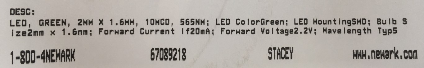
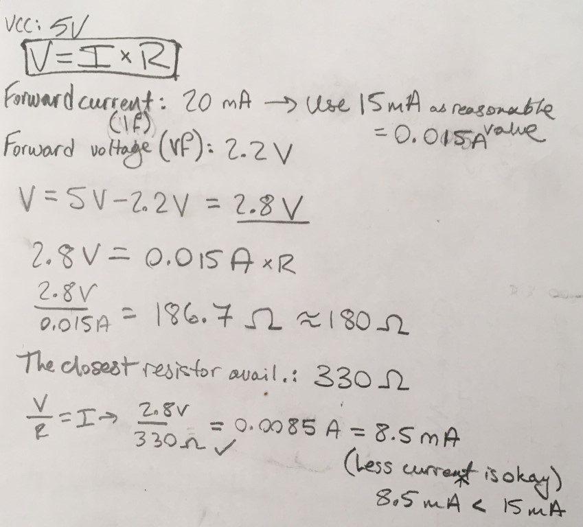
In order to refresh my memory on Ohm’s Law, I took a look at this Evil Mad Scientist article. I then took a look at the specs for the green LED I wanted to add to my board (above) and then did the appropriate calculations (also above). I initially believed that the 330 Ohm resistors that my Lab had would work, but I realized that the package was far too small to solder, so I used a 499 Ohm resistor instead, which still provides enough Amperage for light to be emitted.
Once I knew the necessary components, I began a new project in EAGLE, created a Schematic, and inserted the components using the Fab Library I installed (see above), as well as some other helpful pre-installed libraries, like Sparkfun and Adafruit. I soon realized that all of the components I needed were actually in the Fab library, so I began only using that library. In that library, certain components have specially designed pad layouts that allow for more routes to go under them (which proved useful shortly thereafter).
I then connected all of the base components using nets per the traces shown in the same provided image.
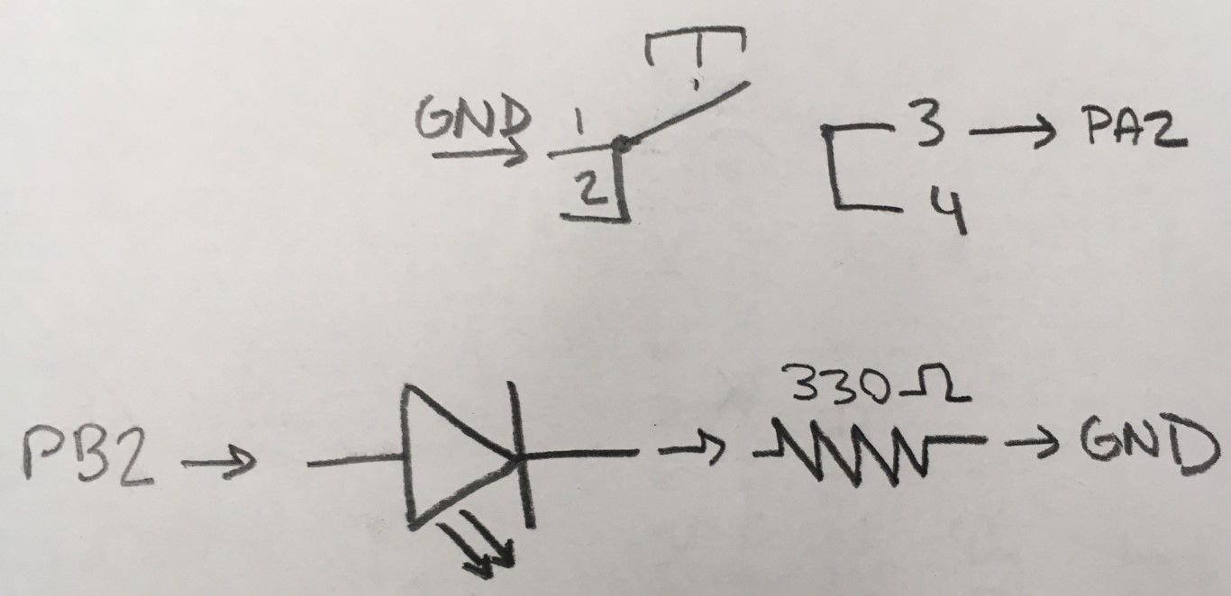
Once I had the base components properly connected, I considered the remaining unused pins on the Tiny to plan out the wiring of my LED and button. I also looked at a pinout diagram at this Instructable. To understand the workings of an SPST button, I looked at this photo and read the data sheet for the button we had available in our Lab. I looked at this DigiKey post to learn how LEDs are drawn in a diagram. Once I determined the wiring of these components (see above photo), I added nets for them in the schematic.
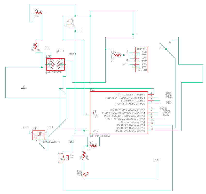
Above, my finished schematic.
Once my schematic was ready, the routing fun began. While the autorouter function does figure out a majority of traces, it is not a flawless solution (or at least I have not uncovered the secret to using it thus far). I went through four major iterations of my board before finally routing everything successfully. I had to take into account the limitations of our CNC mills (which is why I used the aforementioned DRCs); traces had to be at least 12 units wide and have significant clearance from other traces. I ended up having to use three 0 Ohm resistors to jump problematic traces. The entire routing process took many hours (I spent two afternoons working on routing alone), but I learned a lot about the process and it will hopefully not take as long in the future.
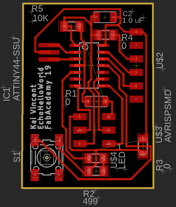
Above, my finished board file. I mimicked the majority of Neil’s design, incorporating jumper resistors where needed to add the button and LED without a major redesign. Note that I tried autorouting straight from the schematic, but this produced multiple issues, and I decided not to ‘reinvent the wheel’ and kept Neil’s major design features.
Once my board was routed, I opened the .brd file from EAGLE in Bantam Tools (the software for our CNC mills) to verify that the DRC had caught all errors (it did). Then, I simply measured my FR1, taped it to the mill bed, and ran the trace (1/64in bit) and outline (1/32 in bit).
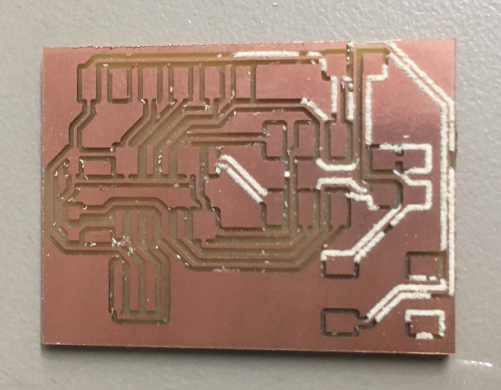
As seen in the above video and photo, the first run didn’t go so well. It turned out that my thickness measurement was too small, and the bit went too deep.
So, I remeasured the board, updated the measurements, and ran the mill again on a different part of the board. This resulted in a great board.
Then, it was time to get the components and begin soldering! I found this Autodesk tutorial that showed me how to generate a Bill of Materials; I used this function to print out a copy in order to keep track of my components. I later added a location attribute to indicate the location on our labeled and inventoried parts wall in our Lab so that I could easily find my components.
Once I had my components, I got to work soldering. I believe that this board took me under two hours to solder, which is a decent improvement over my programmer.
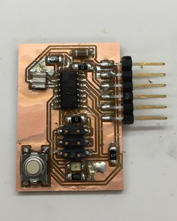
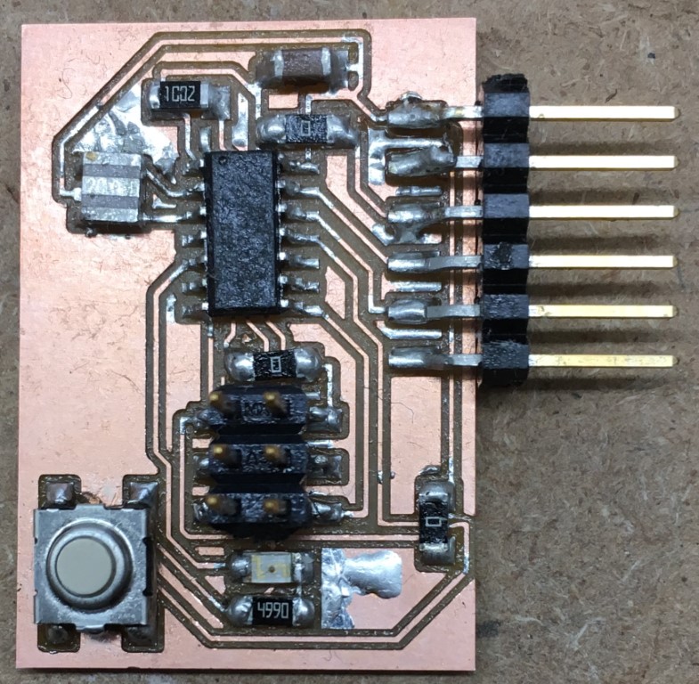
After my board was soldered, I needed to clean the flux off of it. I used a brush and rubbing alcohol to clean it. I realized afterwards that I could have used less flux and had a cleaner board. Above is the dirty board, followed by the clean(er) board.
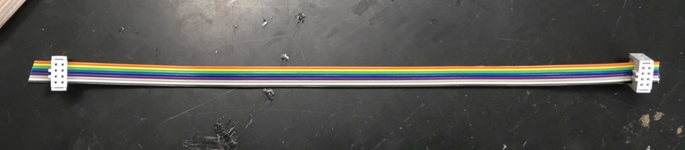
While I let my board dry off, I made my own ribbon cable for programming with the help of one of my instructors. I used pliers to clamp connectors onto a cable with 8 wires.
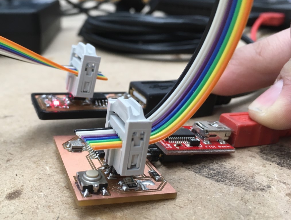
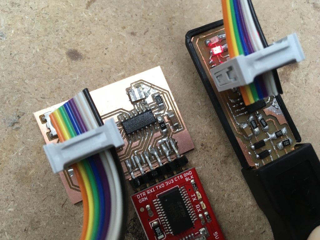
Then, I downloaded Neil’s base EchoHelloWorld code, and imported it into the Arduino IDE. I then plugged in my programmer and connected it with my new ribbon cable to the ISP header on my new board. I also used an FTDI breakout and a mini USB cable to connect the FTDI pins on my board to my computer.
Note: I was having trouble uploading the code to my board via my programmer. I had to add the line #define F_CPU 20000000, which corresponds to the clock speed of my resonator, which is 20 MHz, or 20,000,000 Hz. One of my instructors suggested that I might need drivers for my programmer, which I found here on Adafruit. Once I had these, my computer recognized my programmer in the Device Manager. I then had further trouble, and it was recommended that I burned the bootloader, which I did, and then the programming went smoothly. I also had to add a library in the IDE for the Tiny. I got this link: https://raw.githubusercontent.com/damellis/attiny/ide-1.6.x-boards-manager/package_damellis_attiny_index.json, opened Preferences in the IDE, and pasted the link into the field labeled Additional Boards Manager URLs. Then, I opened the Board Manager and scrolled down until I found the new Tiny library and installed it. Then I was able to select the Tiny44 under boards, verify the package, and select my clock, an External 20MHz resonator.
Once I had the code on my board, I opened up the Serial Monitor in the Arduino IDE and entered a character and hit Enter. Sure enough, my board responded with a message and the character I typed. (If you see a string of weird characters, be sure that you have selected the correct Baud rate in the Serial Monitor).
I tried to program my button and LED into the code. I referred to Arduino’s helpful reference page to refresh my memory on the language, and I referred back to the aforementioned Pinout diagram to see which Tiny pins corresponded to which Arduino pins. Unfortunately, after multiple tries, I still could not get the Button & LED to work. I will come back to this issue at a later time. I have included my code files in the code folder (see below).
UPDATE (3/25/2019): I have resolved the aforementioned issue, as noted here in Week 9.
My EAGLE Schematic & Board files, BOM, and CNC milling file (.zip file)