11. Input devices
This week’s assignment:
group assignment:
probe an input device’s analog levels and digital signals
individual assignment:
measure something: add a sensor to a microcontroller board that you have designed and read it
Probing levels & signals
We measured the input levels of both rotary and linear potentiomenters. Additionally, we programmed an Arduino with an LED to use PWM to use the potentiometers as faders. See the results in the below videos.
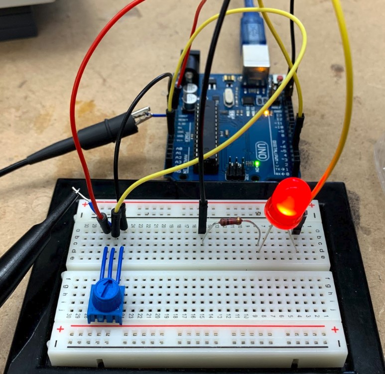
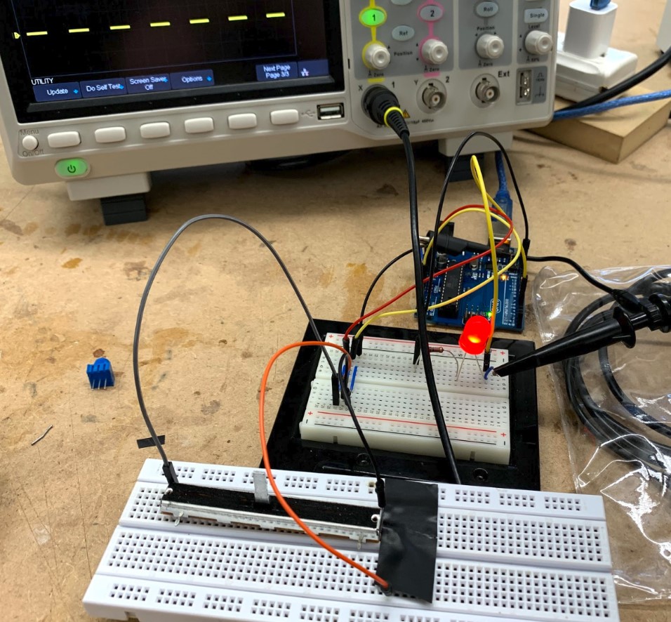
Our setups.
Video & image credit: Will Knight
Making a new Microcontroller board
As documented in week 9, my EchoHelloWorld board has failed. In an attempt to simultaneously satisfy this week’s individual assignment, as well as complete my week 9 assignment, and prepare for next week’s outputs lesson and my final project, I have decided to move on from the EHW board and instead make my own version of Fab Academy 2015 graduate Daniele Ingrassia‘s satshakit, which works just like an Arduino Uno board.
To start, I visited the most up-to-date webpage for the satshakit. I downloaded the BOM and CNC schematic & board files to edit in EAGLE.
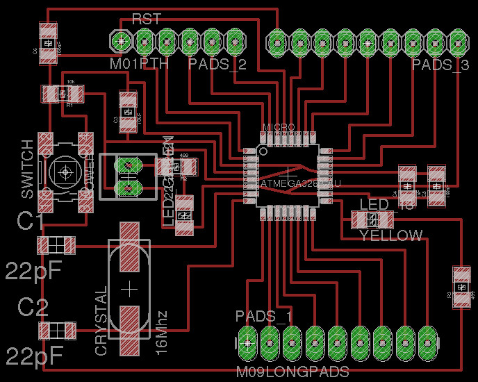
After looking at unmodified satshakit boards milled by Maxine and the original schematic (above), I realized one major improvement that I could make was the slight adjustment of the placement of two capacitors that straddle a trace. Our CNC mills could not separate the trace from the pads of the capacitors because they were too close. To fix this, I first changed the grid size in EAGLE to half the original amount so that I could finely position the two components in question. Then, while holding the Control key (which allowed me to very incrementally move the capacitors), I used the move tool with the Design Rule Check for the 1/64” bit on our mill open so that I could verify that clearance was achieved. Once done, I also added an LED and resistor to the board and connected it to ground and one of the digital pins to serve as an additional onboard “testbed” besides the included LED on Pin 13. I then wrote my name on the board (though I accidentally used the trace tool instead of the line tool, so EAGLE thought I was trying to connect the lines to an existing trace). Finally, I exported the .brd file to the CNC mill for milling. The best milling resulted from using the 1/64” bit for all of the features of the board. (I used the same workflow with the CNC mill as in electronics production week)
Above, a timelapse of me soldering my first Satshakit board.
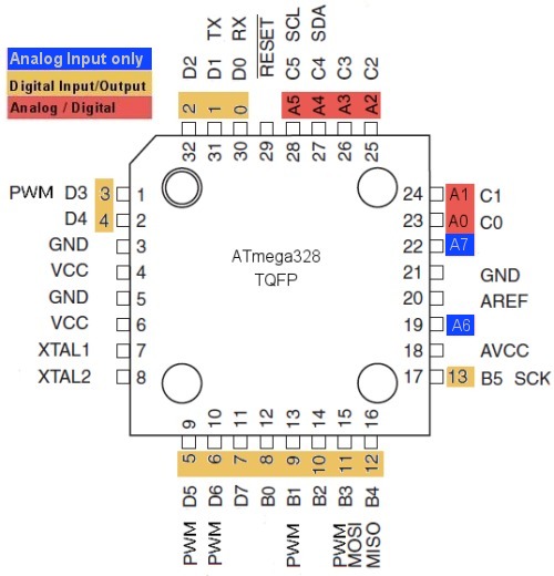
I found the above pinout diagram for the ATMega328 here.
Once I finally soldered a working board, I first burned the bootloader for a blank sketch onto the board per the instructions on the Satshakit site. Then, I tested the basic Blink program, but using my testbed pin, 5, instead of default pin 13:
/*
  Blink

  Turns an LED on for one second, then off for one second, repeatedly.

  Most Arduinos have an on-board LED you can control. On the UNO, MEGA and ZERO
  it is attached to digital pin 13, on MKR1000 on pin 6. LED_BUILTIN is set to
  the correct LED pin independent of which board is used.
  If you want to know what pin the on-board LED is connected to on your Arduino
  model, check the Technical Specs of your board at:
  https://www.arduino.cc/en/Main/Products

  modified 8 May 2014
  by Scott Fitzgerald
  modified 2 Sep 2016
  by Arturo Guadalupi
  modified 8 Sep 2016
  by Colby Newman

  This example code is in the public domain.

  http://www.arduino.cc/en/Tutorial/Blink
*/

// the setup function runs once when you press reset or power the board
void setup() {
  // initialize digital pin LED_BUILTIN as an output.
  pinMode(5, OUTPUT);

}

// the loop function runs over and over again forever
void loop() {
  digitalWrite(5, HIGH);   // turn the LED on (HIGH is the voltage level)
  delay(1000);                       // wait for a second
  digitalWrite(5, LOW);    // turn the LED off by making the voltage LOW
  delay(1000);                       // wait for a second
}

Once I wrote the code, I connected the board to my computer via my programmer and FTDI cable per the above image (from the satshakit site). Note that I had to connect the 5V and ground from the FTDI to the respective pins on both my board and the programmer, and TX/RX pins on the FTDI to the respective pins on the board. Before I uploaded the Blink code, I first had to burn the bootloader (in the Tools menu in the Arduino IDE).
You can see the Blink program running above.
In order to advance on my final project, I decided to use a TMP36 temperature sensor for inputs week. I wrote the following code, based on this very helpful Adafruit tutorial and the Arduino language documentation:
int sensorPin = 0;

void setup() {
  // put your setup code here, to run once:
  Serial.begin(9600);
}

void loop() {
  // put your main code here, to run repeatedly:
  int reading = analogRead(sensorPin);
  float voltage = reading * (5.0 / 1024.0) ;
  float tempC = (voltage - 0.5) * 100 ;
  float tempF = (tempC * 9.0 / 5.0) + 32.0 ;
  Serial.println("The current temperature is "); Serial.print(tempF); Serial.println(" degrees Fahrenheit");
  delay(1000);
}
The pinout of the TMP36 sensor can be seen in the above image, from the aforementioned Adafruit tutorial.
According to the tutorial:
Using the TMP36 is easy, simply connect the left pin to power (2.7-5.5V) and the right pin to ground. Then the middle pin will have an analog voltage that is directly proportional (linear) to the temperature. The analog voltage is independent of the power supply. To convert the voltage to temperature, simply use the basic formula: Temp in °C = [(Vout in mV) - 500] / 10 So for example, if the voltage out is 1V that means that the temperature is ((1000 mV - 500) / 10) = 50 °C

I used the same wiring as in the tutorial, as seen in the above picture from the tutorial, except that I had to draw 5V & GND from the FTDI cable since the board doesn’t have its own pins for such use.
You can see the program successfully at work in the above video.
My Satshakit Design Files (BOM, .brd, .sch, .btm files in .zip folder)