4. Computer controlled cutting
This week’s assignment:
group assignment:
characterize your lasercutter, making test part(s) that vary cutting settings and dimensions
individual assignment:
cut something on the vinylcutter
design, lasercut, and document a parametric press-fit construction kit, accounting for the lasercutter kerf, which can be assembled in multiple ways
Laser Cutter Characterization
A majority of the below documentation would not have been possible without the hard work of two of my classmates at the Charlotte Latin Fab Lab, Katie Chai and Maxine Tan. A big thank you to them for taking the time design the tests and record this information.
Our Lab’s main laser cutter is the 50 watt Epilog Fusion M2. More information can be found about the machine on Epilog’s site. We also have a smaller Epilog laser and a Glowforge. For the purposes of this course, we will mainly be using the M2, so that is the machine we characterized.
To characterize the cutter, we tested different frequency, speed, and power settings, while maintaining the other two settings at set levels.
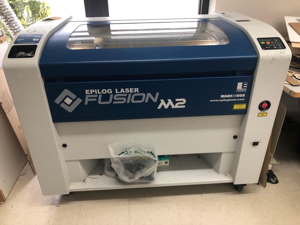
A view of our workhorse laser cutter, the Epilog Fusion M2.
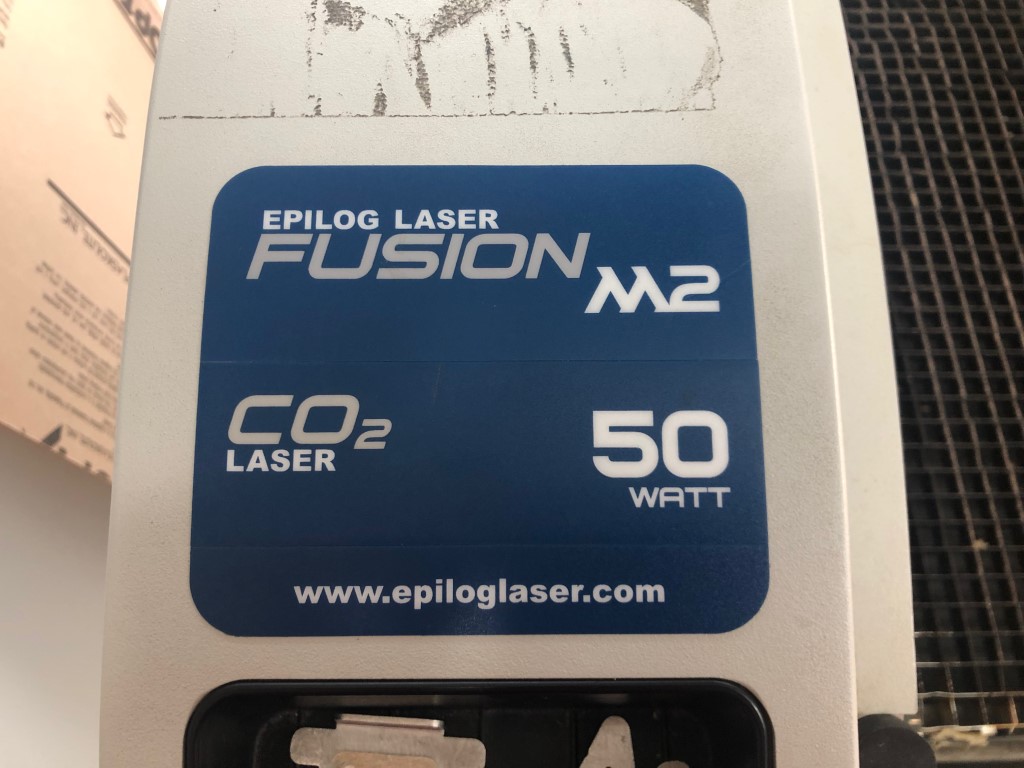
The specification sticker on our laser cutter.
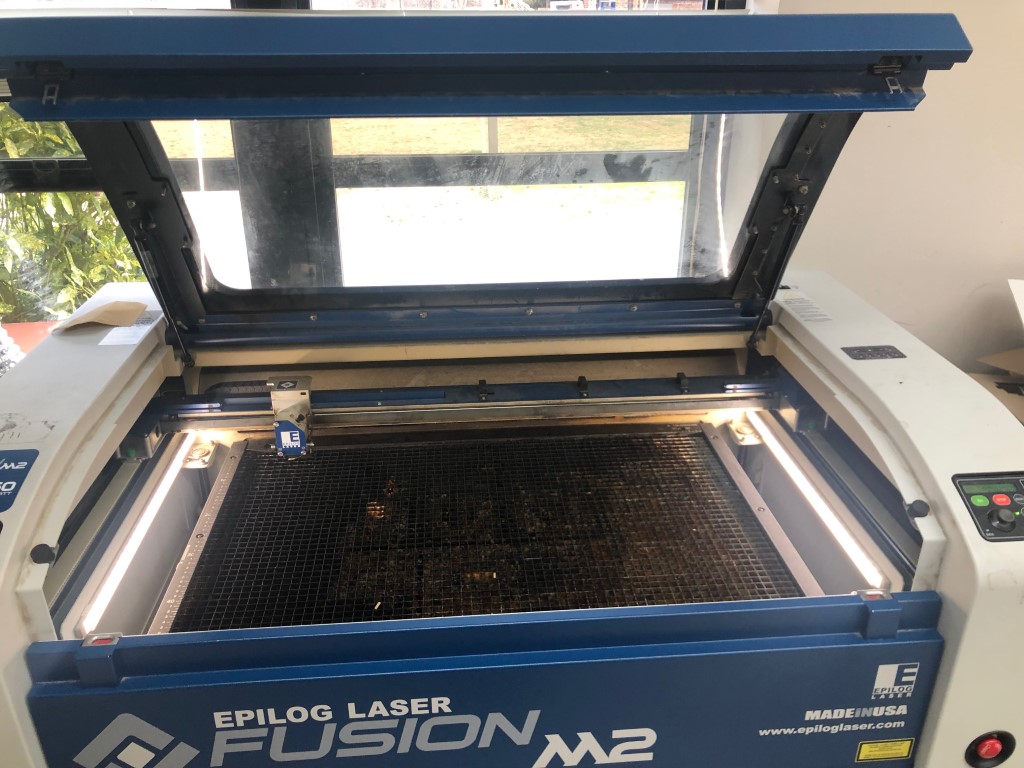
A view of our laser cutter with the hatch open.
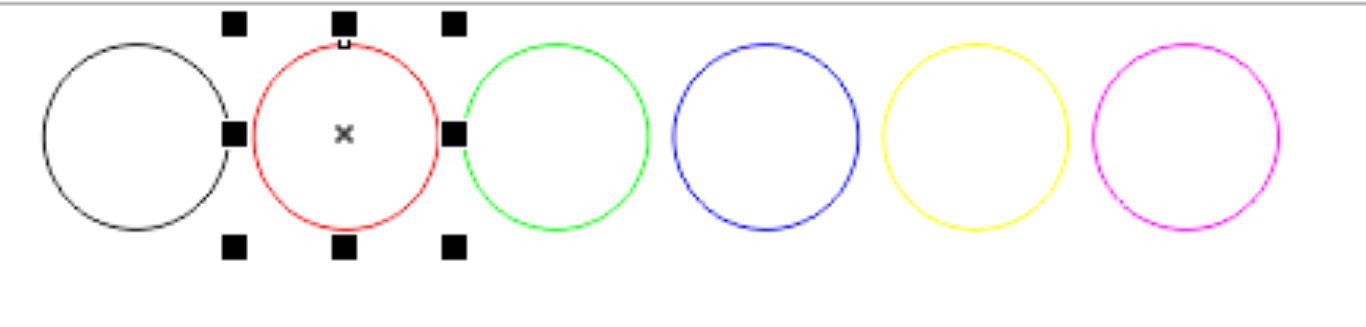
We designed the test file in CorelDRAW, which is our preferred program to prepare files for laser cutting. Each circle had a different RGB color so that we could designate different cutting settings for each circle during each test. We used cardboard with 0.14 in thickness for the tests.
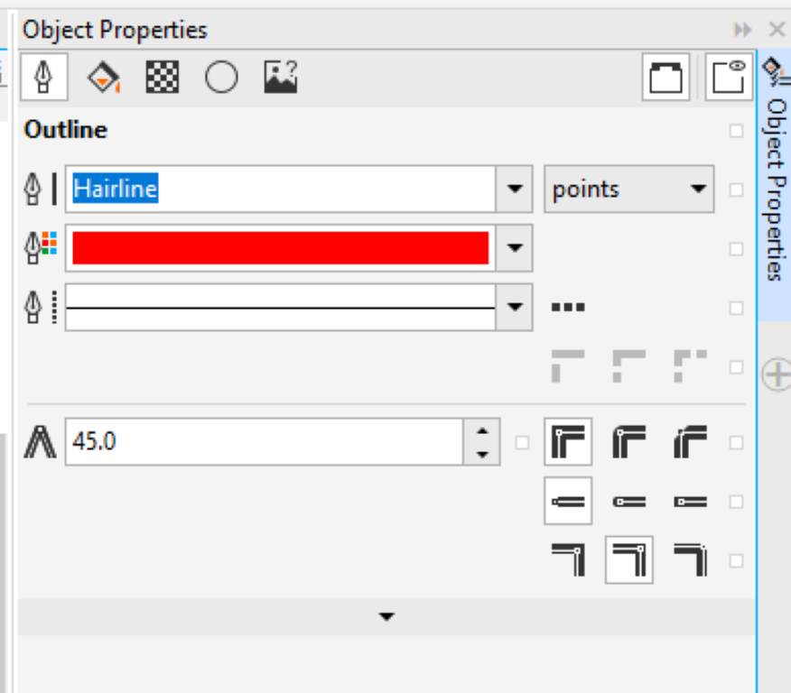
Here you can see the object Outline options in Corel. With the Epilog client, we must use Hairline-thickness lines for the program to recognize it and cut it. We used the stroke color option below the thickness to change the colors of the circles for the Color Mapping. In this way, we were able to run each test with only one “Print” command.
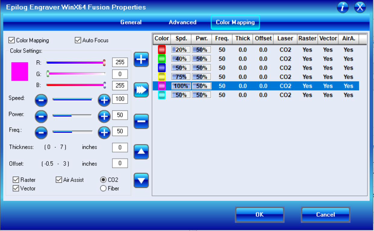
Color mapping settings within the Epilog client for the Speed test. Note that we maintained power and frequency at 50 each, while varying the speeds. We maintained a control on each line with 50% power and speed, and 50 frequency. This pattern was repeated for each test.
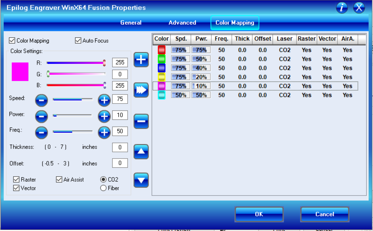
Color mapping settings for the Power test.
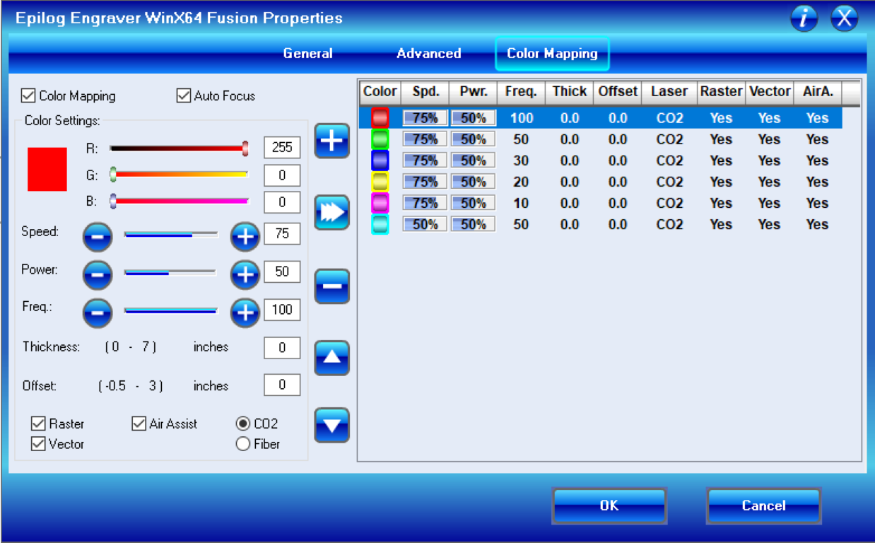
Color mapping settings for the Frequency test.
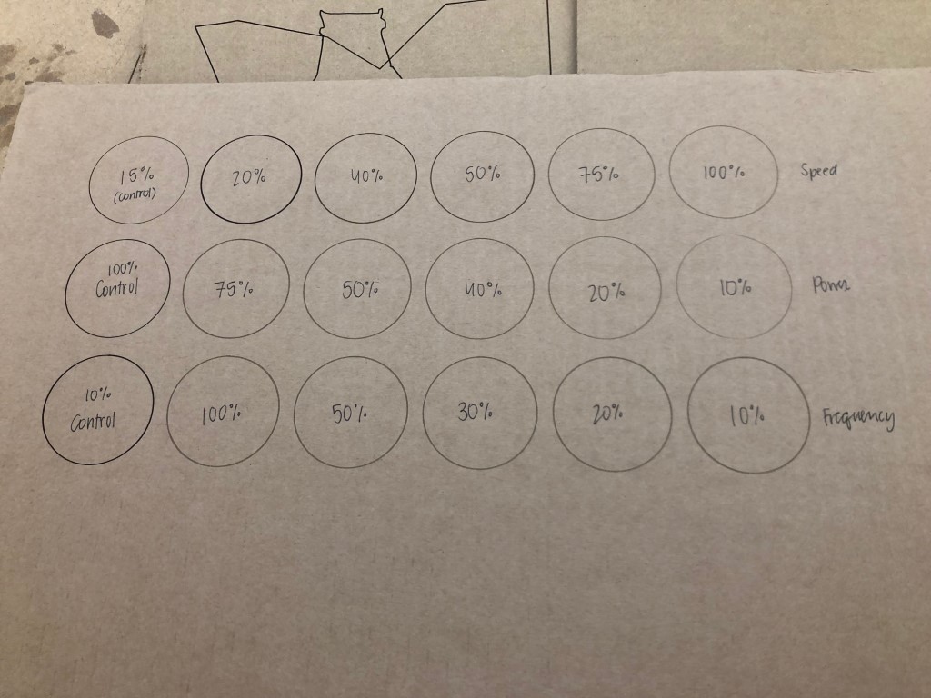
A view of the three tests. Each row is a test. The first cicle in each row is the control specimen. By referring to this chart, we can tell what settings to use when we want to achieve a certain line.
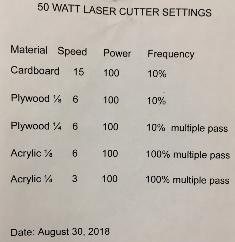
We have this poster in our Lab that we follow for most laser cuts on the M2. For cardboard, we generally run two passes on the prescribed setting (15% speed, 100% power, 10 frequency).
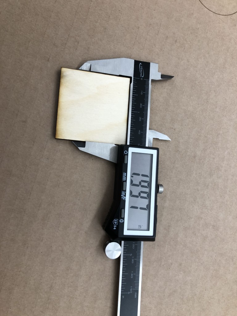
To test the kerf of our laser cutter, we designed a square with 2 inch sides and cut it on 1/8 in plywood. Once it was cut, we measured the actual distance between the square’s sides with calipers. We found that the actual measurement was 1.997 in. By subtracting this from the designed measurement of 2 in, we find that the laser removed .003 from the desired length; If we want an object to be cut and measure an exact measurement, we need to design that object to have an extra .003 in to account for the kerf.
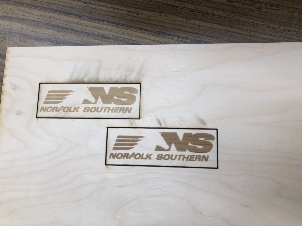
This photo demonstrates how focus can affect an engraving. On the left, you can see how an in-focus cut resulted in a nice, light, engraving as desired. By being out of focus on the right, the wood has a burned appearance. This should be taken into consideration when focusing your laser cutter…you may want lighter (or darker) lines and account for that accordingly.
I used this site to convert HEIC images to JPEGs for this section.
Press-Fit Kit
Note: When I initially began this portion of the assignment, I misunderstood the task and designed a simple press fit kit that was not a puzzle/abstract design. However, I did go over my splicing technique and it was a good practice run for testing user parameters in Fusion. I did restart with a new design, which is what I describe here.
I designed my Press Fit Kit in Fusion 360, as that is the software I have the most experience with, and I hadn’t yet learned much about Parametric Design within Fusion, so I figured it was high time to do so. With the help of my classmate Katie Chai, I learned how to create user parameters, which proved to be essential in designing this kit. I created a few parameters to start, and added more as needed.
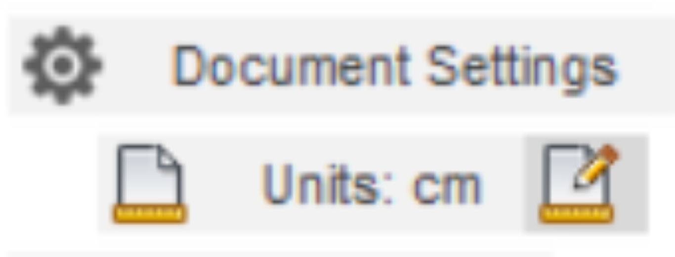
I wanted to use Imperial units (inches) for this design, so I went to the Edit Units menu when I created the design file in Fusion to do so.
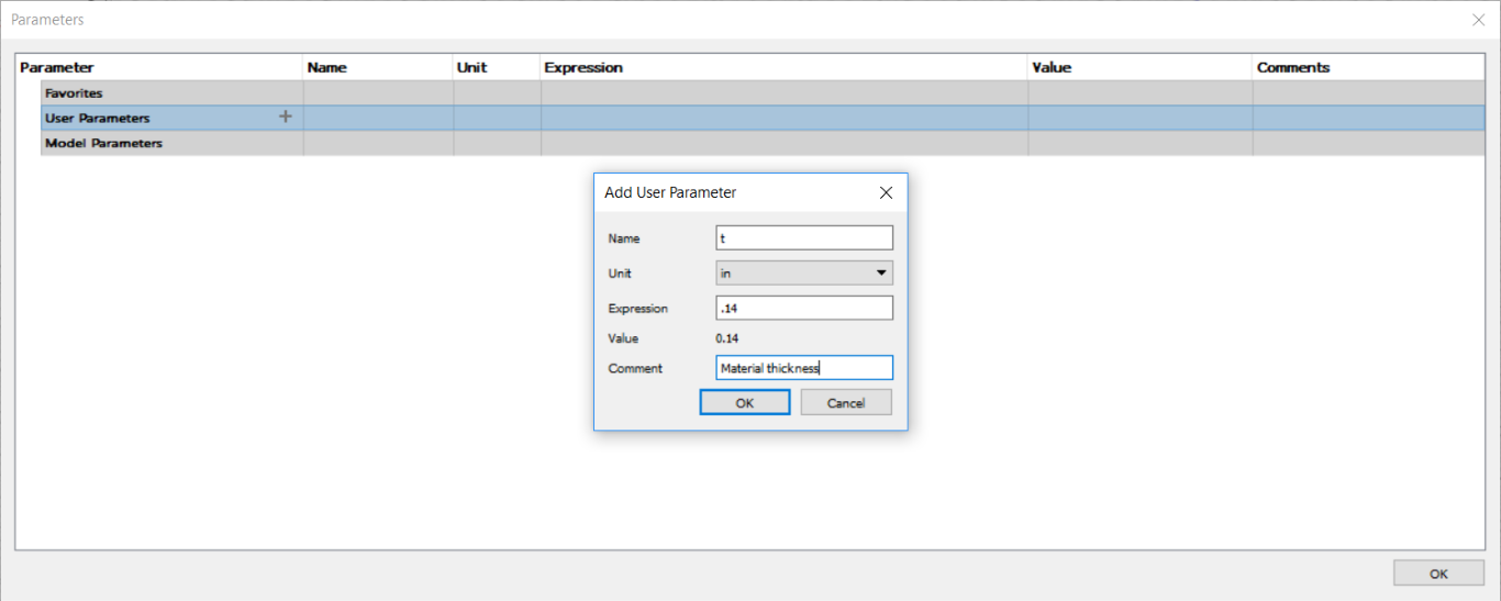
A view of the dialog that appears when creating/editing a parameter. Here, I am establishing a parameter for the material thickness, “t”. Since I am using cardboard with a thickness of 0.14 in, that is what I set the parameter to.
For my kit, I decided to create a set of 4 different shapes that could interlock to construct different objects. I began with a regular hexagon with side length “si”. I then split one of the hexagons in half to form trapezoids. Then, I designed a rectangle with side lengths “si” and “sib” and subsequently split that along the diagonal (length “diag”) to create right triangles. I also established a parameter for the chamfer, “ch”. Each shape has indents with length “i” (for indent) and width “t”, and chamfered edges.
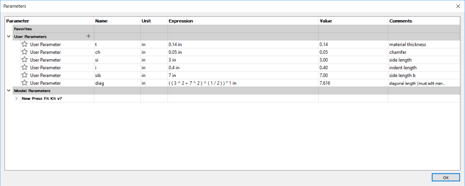
A look at all of the parameters for my kit. Most are pretty self-explanatory with the comments I included. You may notice that the “diag” parameter is all numeric, even though it should reference the other parameters. I use this parameter to slice the rectangle into two triangles; as the diagonal length of the rectangle varies with the side lengths of the rectangle through the Pythagorean Theorem, this should be simple to do. However, square roots (which are necessary for this measurement) cannot be done in Fusion with other parameters under the radical. I learned about this querk and much more about parameter math here and here, respectively. Information about constraints that I used can be found here and info about time as a dimension within Fusion can be found here (this helped me understand why an attached canvas in another design disappeared while I edited a sketch that was created before the insertion of the canvas: in order to maintain continuity while designing)
In the above video, you can see the result of me editing parameters on an earlier design; below, you can see me editing the final kit’s parameters. Note: due to limitations with my screen recording software, it appears that the parameter editing menu does not show up in the recording; see above screenshots to see what this menu looks like.

Generally, I created one indent on a shape, and constructed mirror lines to have replicas of the indents on the sides of the shape. I used the trim tool (keyboard shortcut: t) to eliminate the line segment across the edge of the indent so that the indent would be useable. I extruded these sketches by “t” to create bodies that represented the final cut pieces. I added a chamfer of depth “ch” to the two wedges of each indent. To prepare the design for cutting, I entered my desired parameters, made sure that the bodies didn’t overlap, and then created sketches on the faces of the bodies and exported those as DXF files in Fusion.
On the computer connected to the laser cutter, I opened all of the DXF files in CorelDRAW and arranged the different shapes as I wanted them to cut and sent it to the cutter. As detailed in the cutter documentation above, I used the recommended cardboard settings and ran two runs.
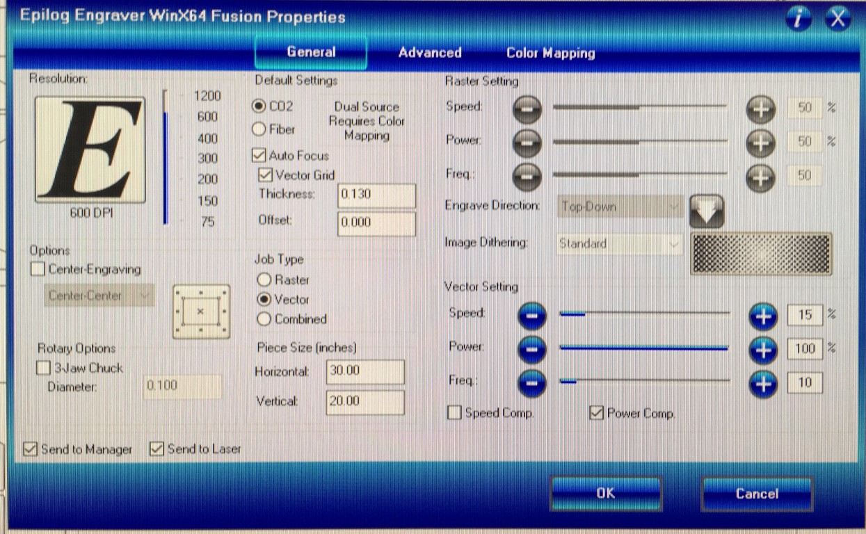
The settings in the Epilog client that I used for this project.
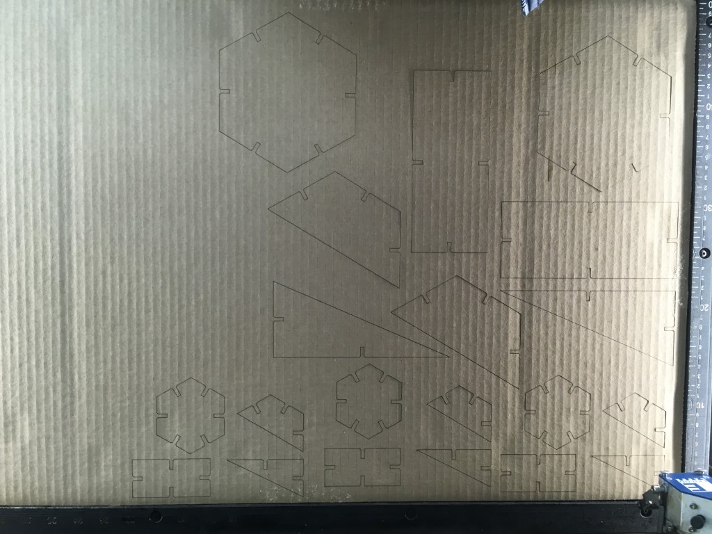
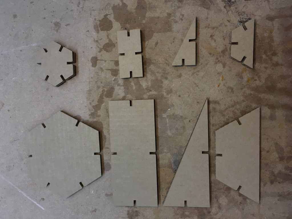
Views of my cut pieces in two sizes inside and removed from the laser cutter, respectively.
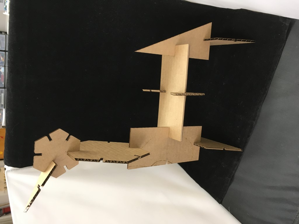
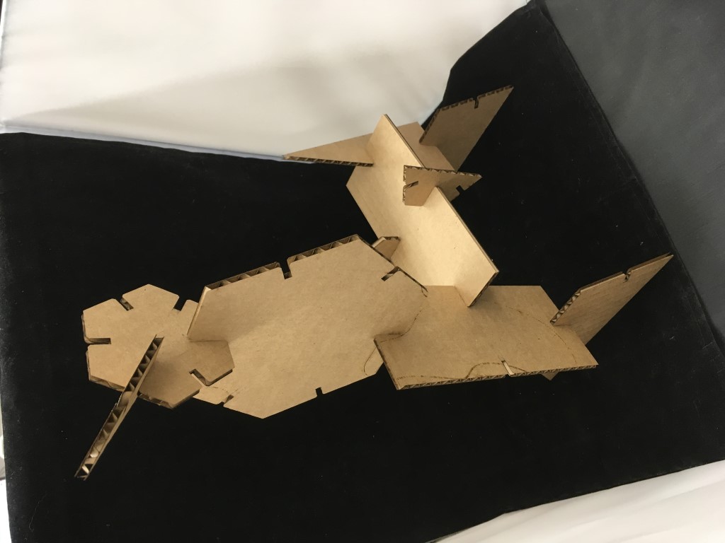
Here, two views of a poodle or camel-looking creation that I put together using the pieces from this project.
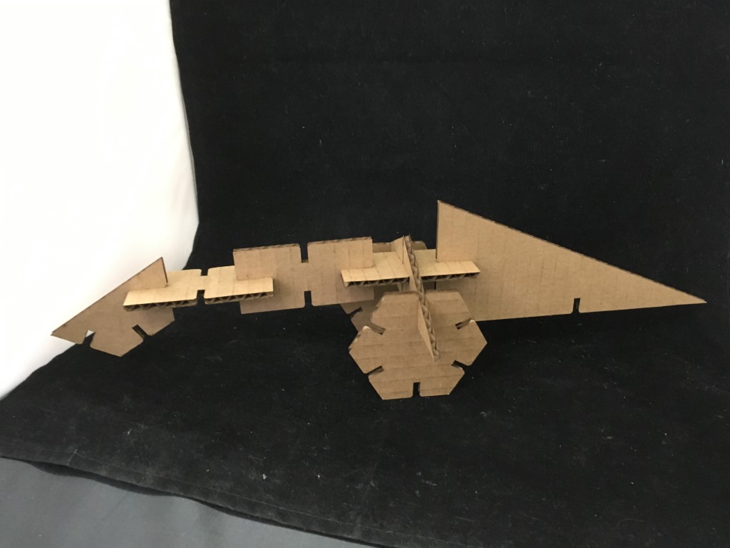
Another, more abstract object I made with the parts.
My Press Fit Design Files (.zip format), including Fusion file, DXFs, & Corel file
Vinyl Cutting
Our Fab Lab has Silhouette Cameo vinyl cutters. I got the compatible Silhouette Studio software at the manufacturer’s website for free.
For this assignment, I decided to make a Fab Academy sticker for our class here at Charlotte Latin.
To start, I got the Fab Academy logo here. I got our school’s logo here.
I utilized the Trace tool in Studio to trace the image files to be compatible for cutting. (I had to use a site to convert my school’s logo from SVG form to a compatible image format; I chose to convert it to PNG using this site)
I aligned my traces so that they would be centered when they cut.
After that, I added the @ symbol and the year using the Text tool. I was able to choose the font and size of the text.
I also added registration marks to the top of the master design. Thank you to Sarah Gibson for pointing me in this direction, as I would not have even known what the term for these nifty things is. I learned a bunch about how they work in these YouTube videos and this article. Essentially, these are useful for layered designs, or designs that incorporate multiple colors. By having a set of marks (usually rectangles) in an exact location for each cut, you can then stack all of your cuts together by connecting these marks together carefully. By using these, I was able to add many colors to my final sticker.
To prepare the desired piece of vinyl for cutting on the Silhouette Cameo, you simply align and press it onto the sticky cut mat (generally align the piece to the top left corner, but this will vary by design). Then take the mat and line it up on the surface of the vinyl cutter, and select “load cut mat” on the screen. Then, send the cut from your computer to the cutter (described below). Once the cut is done, select “unload” on the cutter’s screen.
This video shows the Send dialog in Silhouette Studio that one must use to send their design to cut. Once you hit send, the Cameo will instantly begin cutting. Normally, a cut will take just seconds, but this will vary with the size and complexity of the design.
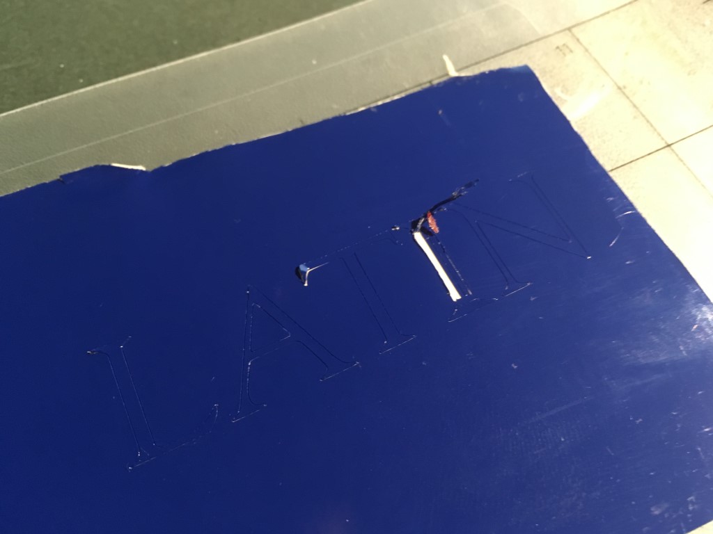
A fault with my school’s logo is that the fancy column in the I is comprised of small lines that are close together. Unfortunately, our vinyl cutter damaged this part of the cut; I plan on manually adding lines to the sticker in the future when I have free time.
Once the designs are cut, it is necessary to “weed” the excess vinyl from the cut. I used a pointy metal probe to pierce the extra vinyl and carefully peel it from the paper backing. Then, I took one of the designs and carefully squeegeed it onto a large piece of transfer tape, repeating the appilcation process with the other cuts, making sure to keep the registration marks aligned. You can see me carefully placing the vinyl onto the transfer tape in the videos above and below.
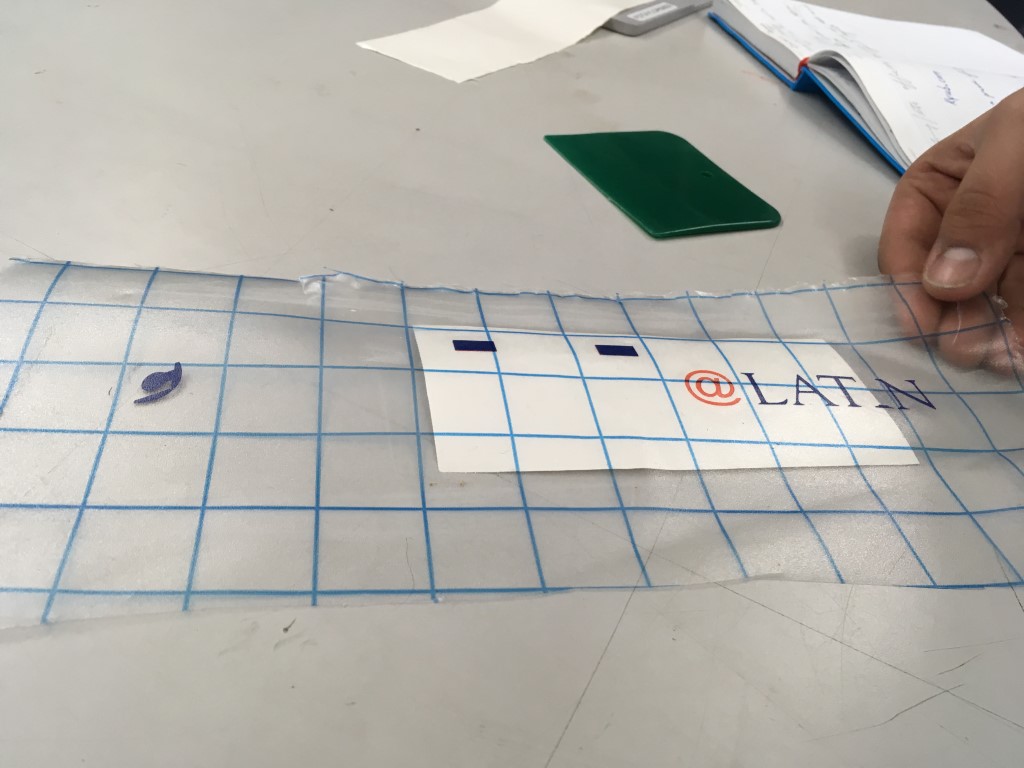
A key part of correctly assembling a design like this one using registration marks is to align the marks as perfectly as possible when placing the vinyl to the transfer tape.
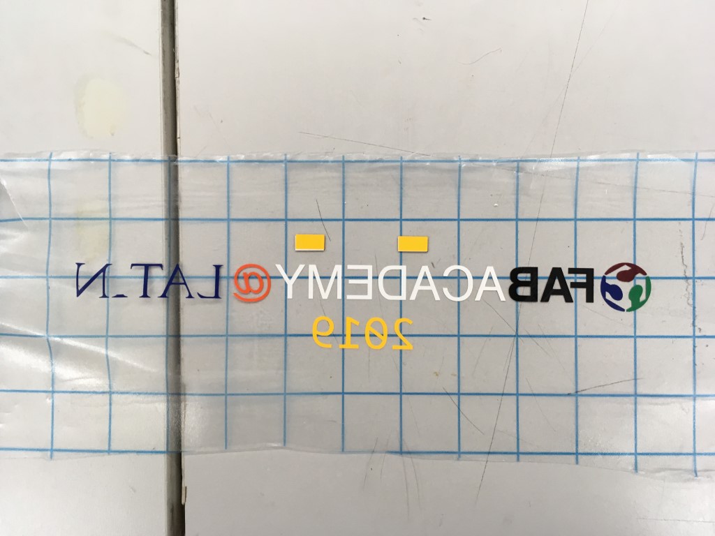
Above, a look at all of the different components of the master design all together on the transfer tape.
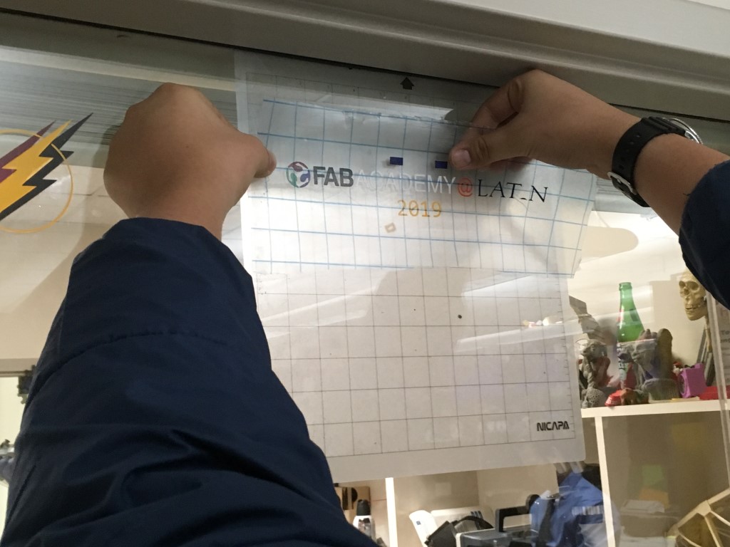
In the above photo and below video, you can see me using a squeegee to carefully apply my sticker to the window.
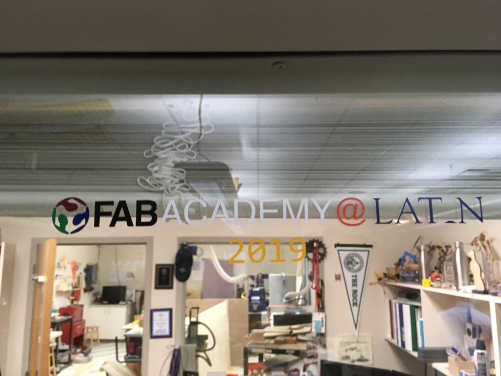
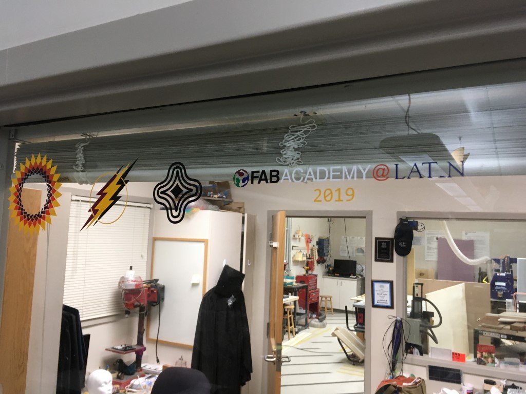
The final project alone and alongside the great stickers of my classmates.
My Vinyl Design Files (.zip format) (Silhouette Studio documents) The entire design is in the file “Master Design.” The rest of the files are the individual parts of the design that I cut on different color vinyl; these files are named with the part of the design and the color of vinyl I used.