9. Embedded programming
This week’s assignment:
group assignment:
compare the performance and development workflows for other architectures
individual assignment:
read a microcontroller data sheet
program your board to do something, with as many different programming languages and programming environments as possible
Comparing Architectures
For our group assignment, we decided to compare the architectures of Raspberry Pi and CHIP.
For the Raspberry Pi, we used a Pi that I had already installed an OS on. I had installed Raspbian Jessie Lite on an RPi Model 3B for the specific use case of streaming from an RPi camera module to a YouTube stream and collecting ADS-B data from flights using a 1090 MHz antenna, connected to the internet via the onboard WiFi antenna. Jessie Lite is the same as standard Jessie, but with no GUI/visual representation, only command line; I only installed the Lite version because that was all that was needed to run the desired programs at the time. Raspbian is a form of Linux, open source. Without the GUI, there are not many advanced programs but you can still do code like normal. Due to setup though, you can’t actually open an IDE to write/upload code. Raspberry Pi is the classic “pocket computer,” featuring:
- Quad Core 1.2GHz Broadcom BCM2837 64bit CPU
- 1GB RAM
- BCM43438 wireless LAN and Bluetooth Low Energy (BLE) on board
- 100 Base Ethernet
- 40-pin extended GPIO
- 4 USB 2 ports
- 4 Pole stereo output and composite video port
- Full size HDMI
- CSI camera port for connecting a Raspberry Pi camera
- DSI display port for connecting a Raspberry Pi touchscreen display
- Micro SD port for loading your operating system and storing data
- Upgraded switched Micro USB power source up to 2.5A
Basic Linux programs & commands
User privelege basics: sudo means you are giving administrator privileges. root is higher than sudo, but not recommended.
Nano: text editor within Linux. Any text based file can be edited in Nano.
sudo nano test_code.py means:
- Sudo: giving admin priv
- Nano: Opens nano
- test_code.py: Opens (If you have an existing document called test_code.py) or Creates file called “test_code.py”
- .py: File extension for Python code
Once done editing file, Ctrl + X to exit & press Y to save
python test_code.py will run the code in test_code.py: in our case, it said Hello World because within the file, we had print (“Hello world”)
sudo apt-get update searches servers for software update
sudo raspi-configopens configuration menu, where options such as WiFi, SSH access, overclocking, keyboard layout, date & time, etc. can be changed
script transcript.log begins transcript of code entered, storing the info in transcript.log, which can be accessed via…
nano transcript .log shows every line of code that has been written after starting transcript
Blinking an LED on RPi
Insert import RPi.GPIO as GPIO in order to use GPIO pins in python code (GPIO: General Purpose In and Out)
Tutorial we used for LED blink code
Our resulting blinking LED (ignore the Arduino board behind the breadboard).
The code (per the above tutorial):
import RPi.GPIO as GPIO # Import Raspberry Pi GPIO library
from time import sleep # Import the sleep function from the time module

GPIO.setwarnings(False) # Ignore warning for now
GPIO.setmode(GPIO.BOARD) # Use physical pin numbering
GPIO.setup(8, GPIO.OUT, initial=GPIO.LOW) # Set pin 8 to be an output pin and set initial value to low (off)

while True: # Run forever
 GPIO.output(8, GPIO.HIGH) # Turn on
 sleep(1) # Sleep for 1 second
 GPIO.output(8, GPIO.LOW) # Turn off
 sleep(1) # Sleep for 1 second
Exploring the CHIP
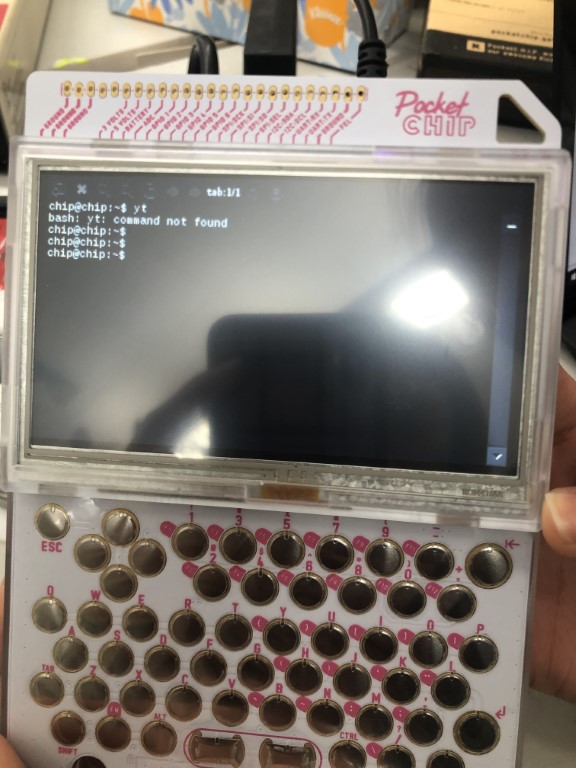
We also had a Pocket CHIP, a version of the CHIP computer with a screen and keyboard attached. It looks like a jumbo version of a Blackberry smartphone. Unfortunately, the business that produced it is no longer operating. Luckily, we were able to find a cached version of the website here.
Katie looked at this tutorial on Instructables to find out how to blink an LED with the CHIP. The OS on the CHIP needed to be updated & a GPIO library needed to be installed, but that operation required a password, which we did not figure out at the time. (At the cached website, however, I later found that the password for chip is chip and the password for root is root) Katie instead decided to code a tip calculator instead. Her code read as follows:
def tipcalc():
    x=float(input("What is the price?"))
    y=float(input("What percent would you like to tip?"))

    y=y/100
    z=x*y

    print "The tip is $", round (z,2)
    print "The total price is $", round (x+z,2)

tipcalc()
Reading a Microcontroller Data Sheet
I looked at the ATTiny44 data sheet recommended on the assignment page. After the first couple of pages with general specifications and diagrams, reading the data sheet seemed like trying to interpret an alien language with my extremely limited experience and knowledge in this area. I was most surprised by the extreme amount of information and level of detail attainable for an object smaller than my pinky nail. I cannot imagine the number of experts and manhours it took to produce and edit this 286-page document.
Programming My Board
To begin, I connected my board & programmer together and to my computer the same way as in my electronics design week. Then, I opened the Arduino IDE & wrote the following code, using pin 8 per my board’s pinout (I have an LED connected to pin 8)
void setup() {
  pinMode(8, OUTPUT);

}

void loop() {
  digitalWrite(8, HIGH);
  delay(1000);
  digitalWrite(8, LOW);
  delay(1000);
}
After I verified the code, I attempted to upload it to my board and immediately began to receive error messages. After reading a few forum threads, I activated verbose mode. The error messages upon uploading look like this:
Arduino: 1.8.8 (Windows 10), Board: "ATtiny24/44/84, ATtiny44, External 20 MHz"

Sketch uses 664 bytes (16%) of program storage space. Maximum is 4096 bytes.
Global variables use 64 bytes (25%) of dynamic memory, leaving 192 bytes for local variables. Maximum is 256 bytes.
C:\Program Files (x86)\Arduino\hardware\tools\avr/bin/avrdude -CC:\Program Files (x86)\Arduino\hardware\tools\avr/etc/avrdude.conf -v -pattiny44 -cusbtiny -Uflash:w:C:\Users\LENOVO~1\AppData\Local\Temp\arduino_build_318311/EchoHelloWorld.ino.hex:i

avrdude: Version 6.3-20171130
         Copyright (c) 2000-2005 Brian Dean, http://www.bdmicro.com/
         Copyright (c) 2007-2014 Joerg Wunsch

         System wide configuration file is "C:\Program Files (x86)\Arduino\hardware\tools\avr/etc/avrdude.conf"

         Using Port                    : usb
         Using Programmer              : usbtiny
avrdude: usbdev_open(): Found USBtinyISP, bus:device: bus-0:\\.\libusb0-0001--0x1781-0x0c9f
         AVR Part                      : ATtiny44
         Chip Erase delay              : 4500 us
         PAGEL                         : P00
         BS2                           : P00
         RESET disposition             : possible i/o
         RETRY pulse                   : SCK
         serial program mode           : yes
         parallel program mode         : yes
         Timeout                       : 200
         StabDelay                     : 100
         CmdexeDelay                   : 25
         SyncLoops                     : 32
         ByteDelay                     : 0
         PollIndex                     : 3
         PollValue                     : 0x53
         Memory Detail                 :

                                  Block Poll               Page                       Polled
           Memory Type Mode Delay Size  Indx Paged  Size   Size #Pages MinW  MaxW   ReadBack
           ----------- ---- ----- ----- ---- ------ ------ ---- ------ ----- ----- ---------
           eeprom        65     6     4    0 no        256    4      0  4000  4500 0xff 0xff
           flash         65     6    32    0 yes      4096   64     64  4500  4500 0xff 0xff
           signature      0     0     0    0 no          3    0      0     0     0 0x00 0x00
           lock           0     0     0    0 no          1    0      0  9000  9000 0x00 0x00
           lfuse          0     0     0    0 no          1    0      0  9000  9000 0x00 0x00
           hfuse          0     0     0    0 no          1    0      0  9000  9000 0x00 0x00
           efuse          0     0     0    0 no          1    0      0  9000  9000 0x00 0x00
           calibration    0     0     0    0 no          1    0      0     0     0 0x00 0x00

         Programmer Type : USBtiny
         Description     : USBtiny simple USB programmer, https://learn.adafruit.com/usbtinyisp
avrdude: programmer operation not supported

avrdude: Using SCK period of 10 usec
avrdude: AVR device initialized and ready to accept instructions

Reading | ################################################## | 100% 0.00s

avrdude: Device signature = 0xffffff (probably .avr8x_mega) (retrying)

Reading | ################################################## | 100% 0.01s

avrdude: Device signature = 0xffffff (probably .avr8x_mega) (retrying)

An error occurred while uploading the sketch
Reading | ################################################## | 100% 0.00s

avrdude: Device signature = 0xffffff (probably .avr8x_mega)
avrdude: Yikes!  Invalid device signature.
         Double check connections and try again, or use -F to override
         this check.


avrdude done.  Thank you.

This report would have more information with
"Show verbose output during compilation"
option enabled in File -> Preferences.
The primary issue identified is that there is a device signature mismatch. Per most of the threads I read, I have most likely bricked my board at this point. Unfortunately, as I write this, I am on vacation 1000 miles away from my Lab, so I don’t have access to an oscilloscope to verify that my board’s crystal is working or further analyze why the board is not functioning. This result is very disheartening, but I hope that I can resolve the issue without having to completely reproduce the board.
Note: I did look at this poupular thread. I verified before I began programming that my board was properly connected to my programmer, I selected the correct COM port, so the issue could be that the crystal is not properly oscillating (but I don’t have an o-scope to check this as explained above) or that there is an issue with flashing/erasing.
UPDATE (3/25/19)
I have returned from vacation. Upon packing up my equipment, I discovered that thew ISP header on my board had lifted off of the board and suspected that that may have been the issue. Today, I used a soldering iron to resolder the header, and luckily, it appears that my board is now working normally. I successfully uploaded a blank sketch from the Arduino IDE and received the following message:
avrdude: Version 6.3-20171130
         Copyright (c) 2000-2005 Brian Dean, http://www.bdmicro.com/
         Copyright (c) 2007-2014 Joerg Wunsch

         System wide configuration file is "C:\Program Files (x86)\Arduino\hardware\tools\avr/etc/avrdude.conf"

         Using Port                    : usb
         Using Programmer              : usbtiny
avrdude: usbdev_open(): Found USBtinyISP, bus:device: bus-0:\\.\libusb0-0001--0x1781-0x0c9f
         AVR Part                      : ATtiny44
         Chip Erase delay              : 4500 us
         PAGEL                         : P00
         BS2                           : P00
         RESET disposition             : possible i/o
         RETRY pulse                   : SCK
         serial program mode           : yes
         parallel program mode         : yes
         Timeout                       : 200
         StabDelay                     : 100
         CmdexeDelay                   : 25
         SyncLoops                     : 32
         ByteDelay                     : 0
         PollIndex                     : 3
         PollValue                     : 0x53
         Memory Detail                 :

                                  Block Poll               Page                       Polled
           Memory Type Mode Delay Size  Indx Paged  Size   Size #Pages MinW  MaxW   ReadBack
           ----------- ---- ----- ----- ---- ------ ------ ---- ------ ----- ----- ---------
           eeprom        65     6     4    0 no        256    4      0  4000  4500 0xff 0xff
           flash         65     6    32    0 yes      4096   64     64  4500  4500 0xff 0xff
           signature      0     0     0    0 no          3    0      0     0     0 0x00 0x00
           lock           0     0     0    0 no          1    0      0  9000  9000 0x00 0x00
           lfuse          0     0     0    0 no          1    0      0  9000  9000 0x00 0x00
           hfuse          0     0     0    0 no          1    0      0  9000  9000 0x00 0x00
           efuse          0     0     0    0 no          1    0      0  9000  9000 0x00 0x00
           calibration    0     0     0    0 no          1    0      0     0     0 0x00 0x00

         Programmer Type : USBtiny
         Description     : USBtiny simple USB programmer, https://learn.adafruit.com/usbtinyisp
avrdude: programmer operation not supported

avrdude: Using SCK period of 10 usec
avrdude: AVR device initialized and ready to accept instructions

Reading | ################################################## | 100% 0.01s

avrdude: Device signature = 0x1e9207 (probably t44)
avrdude: NOTE: "flash" memory has been specified, an erase cycle will be performed
         To disable this feature, specify the -D option.
avrdude: erasing chip
avrdude: Using SCK period of 10 usec
avrdude: reading input file "C:\Users\LENOVO~1\AppData\Local\Temp\arduino_build_577261/sketch_mar25a.ino.hex"
avrdude: writing flash (284 bytes):

Writing | ################################################## | 100% 0.58s

avrdude: 284 bytes of flash written
avrdude: verifying flash memory against C:\Users\LENOVO~1\AppData\Local\Temp\arduino_build_577261/sketch_mar25a.ino.hex:
avrdude: load data flash data from input file C:\Users\LENOVO~1\AppData\Local\Temp\arduino_build_577261/sketch_mar25a.ino.hex:
avrdude: input file C:\Users\LENOVO~1\AppData\Local\Temp\arduino_build_577261/sketch_mar25a.ino.hex contains 284 bytes
avrdude: reading on-chip flash data:

Reading | ################################################## | 100% 0.59s

avrdude: verifying ...
avrdude: 284 bytes of flash verified

avrdude done.  Thank you.
Discovery #2: The Button code I tried to use during Week 7 is now working as seen in the video above.
UPDATE #2 (3/30/19)
Since fixing the board, I have been unsuccessful in running a new program on it. After successfully sending new code to the board and even wiping the memory, the button program stil keeps working. Following multiple attempts to troubleshoot my EchoHelloWorld board, I cannot figure out the issue. I have decided to instead edit the satshakit for use in the Input/Output weeks, my final project, and this assignment. I’ll update this page with further progress, while you can find info regarding my version of the satshakit here in my Input week documentation (week 11).
UPDATE #3 (4/16/19)
After successfully working on Inputs & Outputs, I have come back to Embedded Programming, using the modified Satshakit that I designed in Inputs Week. I have decided to work to get my testbed LED blinking using Arduino IDE, Powershell, and Atmel Studio.
Arduino
I used the example Blink code & changed the pin to reflect my board design. I also changed the on time to .5 seconds to test it out.
/*
  Blink

  Turns an LED on for one second, then off for one second, repeatedly.

  Most Arduinos have an on-board LED you can control. On the UNO, MEGA and ZERO
  it is attached to digital pin 13, on MKR1000 on pin 6. LED_BUILTIN is set to
  the correct LED pin independent of which board is used.
  If you want to know what pin the on-board LED is connected to on your Arduino
  model, check the Technical Specs of your board at:
  https://www.arduino.cc/en/Main/Products

  modified 8 May 2014
  by Scott Fitzgerald
  modified 2 Sep 2016
  by Arturo Guadalupi
  modified 8 Sep 2016
  by Colby Newman

  This example code is in the public domain.

  http://www.arduino.cc/en/Tutorial/Blink
*/

// the setup function runs once when you press reset or power the board
void setup() {
  // initialize digital pin LED_BUILTIN as an output.
  pinMode(5, OUTPUT);
}

// the loop function runs over and over again forever
void loop() {
  digitalWrite(5, HIGH);   // turn the LED on (HIGH is the voltage level)
  delay(500);                       // wait for a second
  digitalWrite(5, LOW);    // turn the LED off by making the voltage LOW
  delay(1000);                       // wait for a second
}
Note: Likely due to pin overlap from my Inputs code (the SCK pin was used to receive data from the temp. sensor), my board refused to take new code or a bootloader. Through trial and error, I discovered that I could successfully reprogram my board by holding down the Reset button while programming the board. I also had the jumper from RST on my ISP programmer connected to the wrong RST pin on my board, so that may have had something to do with it. In any case, I resolved the issue and it programs normally now.
UPDATE #4 (6/1/19)
A lot has happened since the last update! After successfully running the Blink code via Arduino, I fried my Satshakit due to power and ground shorting out. I am now using my Satshakit with networking capabilities that I have used for various assignments since then.
C++
I followed this tutorial from Lady Ada to write the blink code in C++. Note that my comments within the code are in parentheses, while those without parentheses are original comments from the author, Lady Ada. Her code was for an ATTiny, so I had to modify the code to match my Mega328P and the pin I wanted to use (pin 13, which is PB5 on the Mega).
My code:
/*
 * KaiBlink.c
 *
 * Created: 6/1/2019 10:51:59 AM
 * Author : LENOVO USER
 */
#define F_CPU 16000000
// this is the header file that tells the compiler what pins and ports, etc.
// are available on this chip.
#include <avr/io.h>

// define what pins the LEDs are connected to.
// in reality, PD6 is really just '6'
// (I, Kai, have updated this to PB5, which is pin 13 on the Mega328P)
#define LED PB5

// Some macros that make the code more readable
#define output_low(port,pin) port &= ~(1<<pin)
#define output_high(port,pin) port |= (1<<pin)
#define set_input(portdir,pin) portdir &= ~(1<<pin)
#define set_output(portdir,pin) portdir |= (1<<pin)

// this is just a program that 'kills time' in a calibrated method
void delay_ms(uint8_t ms) {
    uint16_t delay_count = F_CPU / 17500;
    volatile uint16_t i;

    while (ms != 0) {
        for (i=0; i != delay_count; i++);
        ms--;
    }
}

int main(void) {
    // initialize the direction of PORTD #6 to be an output
    // (edited from DDRD to DDRB to reflect pin change noted above)
    set_output(DDRB, LED);

    while (1) {
        // turn on the LED for 200ms
        // (edited from PORTD to PORTB to reflect pin change noted above)
        output_high(PORTB, LED);
        delay_ms(200);
        // now turn off the LED for another 200ms
        output_low(PORTB, LED);
        delay_ms(200);
// now start over
   }
}
At first, I tried following the programming workflow that I used to program the FabTinyISP through Powershell with make and avr-dude. However, this didn’t work. After some researching, I learned that I could carry out the entire programming process inside Atmel Studio with a little bit of work.
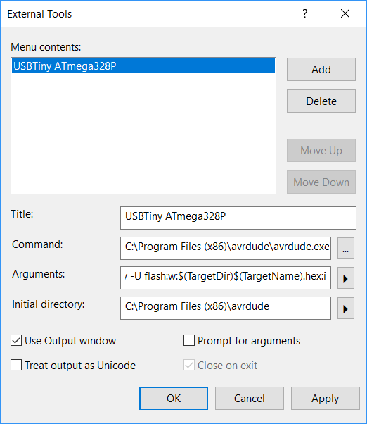
This article was invaluable in helping me use a programmer. I had to follow Step 1 create a new tool in Atmel Studio, as seen in the screenshot above.
Then, all I had to do was debug my program and then produce the “release” of the code. After I did that, I followed Step 2 of the above article to program the board. Note that I would have normally used my FabTinyISP to program my board, but I did not have one at my disposal at the time, so I used a Sparkfun Tiny Programmer that functions similarly. I looked at the product page to verify the pinout of the programmer.
You can see the blinking functioning in the above video.
Output from programmer in Atmel Studio:
avrdude.exe: Version 5.11, compiled on Sep  2 2011 at 19:38:36
             Copyright (c) 2000-2005 Brian Dean, http://www.bdmicro.com/
             Copyright (c) 2007-2009 Joerg Wunsch

             System wide configuration file is "C:\Program Files (x86)\avrdude\avrdude.conf"

             Using Port                    : lpt1
             Using Programmer              : usbtiny
avrdude: usbdev_open(): Found USBtinyISP, bus:device: bus-0:\\.\libusb0-0001--0x1781-0x0c9f
             AVR Part                      : ATMEGA328P
             Chip Erase delay              : 9000 us
             PAGEL                         : PD7
             BS2                           : PC2
             RESET disposition             : dedicated
             RETRY pulse                   : SCK
             serial program mode           : yes
             parallel program mode         : yes
             Timeout                       : 200
             StabDelay                     : 100
             CmdexeDelay                   : 25
             SyncLoops                     : 32
             ByteDelay                     : 0
             PollIndex                     : 3
             PollValue                     : 0x53
             Memory Detail                 :

                                      Block Poll               Page                       Polled
               Memory Type Mode Delay Size  Indx Paged  Size   Size #Pages MinW  MaxW   ReadBack
               ----------- ---- ----- ----- ---- ------ ------ ---- ------ ----- ----- ---------
               eeprom        65    20     4    0 no       1024    4      0  3600  3600 0xff 0xff
                                      Block Poll               Page                       Polled
               Memory Type Mode Delay Size  Indx Paged  Size   Size #Pages MinW  MaxW   ReadBack
               ----------- ---- ----- ----- ---- ------ ------ ---- ------ ----- ----- ---------
               flash         65     6   128    0 yes     32768  128    256  4500  4500 0xff 0xff
                                      Block Poll               Page                       Polled
               Memory Type Mode Delay Size  Indx Paged  Size   Size #Pages MinW  MaxW   ReadBack
               ----------- ---- ----- ----- ---- ------ ------ ---- ------ ----- ----- ---------
               lfuse          0     0     0    0 no          1    0      0  4500  4500 0x00 0x00
                                      Block Poll               Page                       Polled
               Memory Type Mode Delay Size  Indx Paged  Size   Size #Pages MinW  MaxW   ReadBack
               ----------- ---- ----- ----- ---- ------ ------ ---- ------ ----- ----- ---------
               hfuse          0     0     0    0 no          1    0      0  4500  4500 0x00 0x00
                                      Block Poll               Page                       Polled
               Memory Type Mode Delay Size  Indx Paged  Size   Size #Pages MinW  MaxW   ReadBack
               ----------- ---- ----- ----- ---- ------ ------ ---- ------ ----- ----- ---------
               efuse          0     0     0    0 no          1    0      0  4500  4500 0x00 0x00
                                      Block Poll               Page                       Polled
               Memory Type Mode Delay Size  Indx Paged  Size   Size #Pages MinW  MaxW   ReadBack
               ----------- ---- ----- ----- ---- ------ ------ ---- ------ ----- ----- ---------
               lock           0     0     0    0 no          1    0      0  4500  4500 0x00 0x00
                                      Block Poll               Page                       Polled
               Memory Type Mode Delay Size  Indx Paged  Size   Size #Pages MinW  MaxW   ReadBack
               ----------- ---- ----- ----- ---- ------ ------ ---- ------ ----- ----- ---------
               calibration    0     0     0    0 no          1    0      0     0     0 0x00 0x00
                                      Block Poll               Page                       Polled
               Memory Type Mode Delay Size  Indx Paged  Size   Size #Pages MinW  MaxW   ReadBack
               ----------- ---- ----- ----- ---- ------ ------ ---- ------ ----- ----- ---------
               signature      0     0     0    0 no          3    0      0     0     0 0x00 0x00

             Programmer Type : USBtiny
             Description     : USBtiny simple USB programmer, http://www.ladyada.net/make/usbtinyisp/
avrdude.exe: programmer operation not supported

avrdude.exe: Using SCK period of 10 usec
CMD: [ac 53 00 00] [00 00 53 00]
avrdude.exe: AVR device initialized and ready to accept instructions

Reading | CMD: [30 00 00 00] [00 30 00 1e]
CMD: [30 00 01 00] [00 30 00 95]
################CMD: [30 00 02 00] [00 30 00 0f]
################################## | 100% 0.01s

avrdude.exe: Device signature = 0x1e950f
CMD: [50 00 00 00] [00 50 00 ff]
avrdude.exe: safemode read 1, lfuse value: ff
CMD: [50 00 00 00] [00 50 00 ff]
avrdude.exe: safemode read 2, lfuse value: ff
CMD: [50 00 00 00] [00 50 00 ff]
avrdude.exe: safemode read 3, lfuse value: ff
avrdude.exe: safemode: lfuse reads as FF
CMD: [58 08 00 00] [00 58 08 de]
avrdude.exe: safemode read 1, hfuse value: de
CMD: [58 08 00 00] [00 58 08 de]
avrdude.exe: safemode read 2, hfuse value: de
CMD: [58 08 00 00] [00 58 08 de]
avrdude.exe: safemode read 3, hfuse value: de
avrdude.exe: safemode: hfuse reads as DE
CMD: [50 08 00 00] [00 50 08 fd]
avrdude.exe: safemode read 1, efuse value: 5
CMD: [50 08 00 00] [00 50 08 fd]
avrdude.exe: safemode read 2, efuse value: 5
CMD: [50 08 00 00] [00 50 08 fd]
avrdude.exe: safemode read 3, efuse value: 5
avrdude.exe: safemode: efuse reads as 5
avrdude.exe: NOTE: FLASH memory has been specified, an erase cycle will be performed
             To disable this feature, specify the -D option.
CMD: [a0 03 fc 00] [00 a0 03 ff]
CMD: [a0 03 fd 00] [00 a0 03 ff]
CMD: [a0 03 fe 00] [00 a0 03 ff]
CMD: [a0 03 ff 00] [00 a0 03 ff]
avrdude.exe: erasing chip
CMD: [ac 80 00 00] [00 ac 80 00]
avrdude.exe: Using SCK period of 10 usec
CMD: [ac 53 00 00] [00 ac 53 00]
avrdude.exe: reading input file "C:\Users\LENOVO USER\Documents\Atmel Studio\7.0\KaiBlink\KaiBlink\Release\KaiBlink.hex"
avrdude.exe: writing flash (208 bytes):

Writing | CMD: [4c 00 00 00] [00 4c 00 00]
##############################CMD: [4c 00 40 00] [cf 4c 00 40]
#################### | 100% 0.25s

avrdude.exe: 208 bytes of flash written
avrdude.exe: verifying flash memory against C:\Users\LENOVO USER\Documents\Atmel Studio\7.0\KaiBlink\KaiBlink\Release\KaiBlink.hex:
avrdude.exe: load data flash data from input file C:\Users\LENOVO USER\Documents\Atmel Studio\7.0\KaiBlink\KaiBlink\Release\KaiBlink.hex:
avrdude.exe: input file C:\Users\LENOVO USER\Documents\Atmel Studio\7.0\KaiBlink\KaiBlink\Release\KaiBlink.hex contains 208 bytes
avrdude.exe: reading on-chip flash data:

Reading | ################################################## | 100% 0.19s

avrdude.exe: verifying ...
avrdude.exe: 208 bytes of flash verified

CMD: [50 00 00 00] [cf 50 00 ff]
avrdude.exe: safemode read 1, lfuse value: ff
CMD: [50 00 00 00] [00 50 00 ff]
avrdude.exe: safemode read 2, lfuse value: ff
CMD: [50 00 00 00] [00 50 00 ff]
avrdude.exe: safemode read 3, lfuse value: ff
avrdude.exe: safemode: lfuse reads as FF
CMD: [58 08 00 00] [00 58 08 de]
avrdude.exe: safemode read 1, hfuse value: de
CMD: [58 08 00 00] [00 58 08 de]
avrdude.exe: safemode read 2, hfuse value: de
CMD: [58 08 00 00] [00 58 08 de]
avrdude.exe: safemode read 3, hfuse value: de
avrdude.exe: safemode: hfuse reads as DE
CMD: [50 08 00 00] [00 50 08 fd]
avrdude.exe: safemode read 1, efuse value: 5
CMD: [50 08 00 00] [00 50 08 fd]
avrdude.exe: safemode read 2, efuse value: 5
CMD: [50 08 00 00] [00 50 08 fd]
avrdude.exe: safemode read 3, efuse value: 5
avrdude.exe: safemode: efuse reads as 5
avrdude.exe: safemode: Fuses OK

avrdude.exe done.  Thank you.