20. Project development
Project synthesis
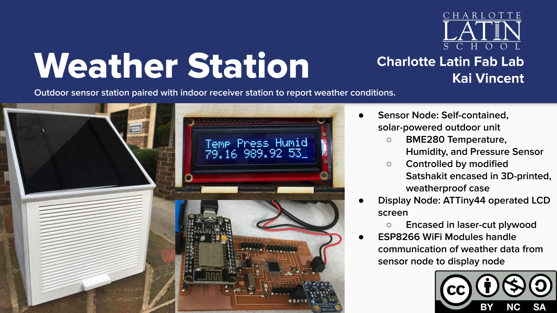
I have built an outdoor sensor station paired with indoor receiver station to report weather conditions. It is comprised of two units:
-
Sensor Node: Self-contained, solar-powered outdoor unit BME280 Temperature, Humidity, and Pressure Sensor Controlled by modified Satshakit encased in 3D-printed, weatherproof case
-
Display Node: ATTiny44 operated LCD screen Encased in laser-cut plywood
Two ESP8266 WiFi Modules handle communication of weather data from sensor node to display node.
You can watch the successful final presentations of all of the members from my Lab here or in the below video at ~27 minute mark:
Fab-20190619B_Final05 from Academany on Vimeo.
Timing
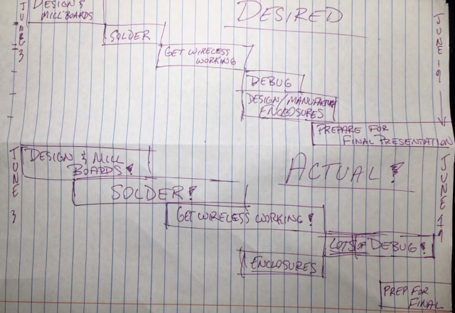
In the above photo, you can see the desired and actual timing of my final project development. I was done with school by June 3rd and presented my project on the 19th. The two and a half weeks in between were an absolute whirlwind. I hoped to spend 2-3 days each on designing/milling my boards, soldering them. Then I would use 3-4 days to get wireless communications functioning, leaving me another week or so to debug my code, design and manufacture my enclosures, and prepare for my presentation. As you can see in my photo, the schedule did not go according to plan whatsoever. Designing my boards took a little longer than expected, but soldering and networking used most of the two weeks I had at my disposal. I had to split my focus between the two just to get everything barely working, and then I had to rush through my enclosure designing and making & my presentation prep, while also debugging all of my work, which was not truly finished until hours prior to my final presentation. This variation of timing required me to prioritize certain elements of my project over others: I knew I needed to have working boards and code more than I needed any enclosures, which I only worked on while the other components were on hold. This timing somewhat replicates the supply-demand timing balance that Neil often mentions: I had far too little supply of time, while having various demands of varying importance. I definitely did not enjoy having to rush through this project, and would highly recommend to others that they complete as much of their project as possible prior to the end of the course; unfortunately, I did not have time to do this myself besides my full school courseload and a minimum of 20-30 hours per week spent on this course, as well as other activities.
Board design and production
My boards are based on the modified Satshakits I used for many purposes during the course, with the addition of female headers for the wireless modules, logic level converters, and the sensor/LCD. I designed the boards in EAGLE.
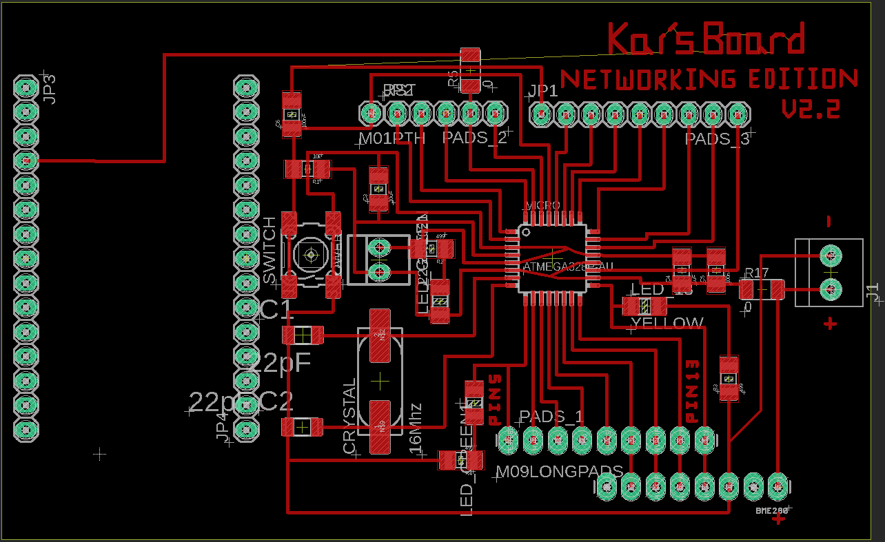
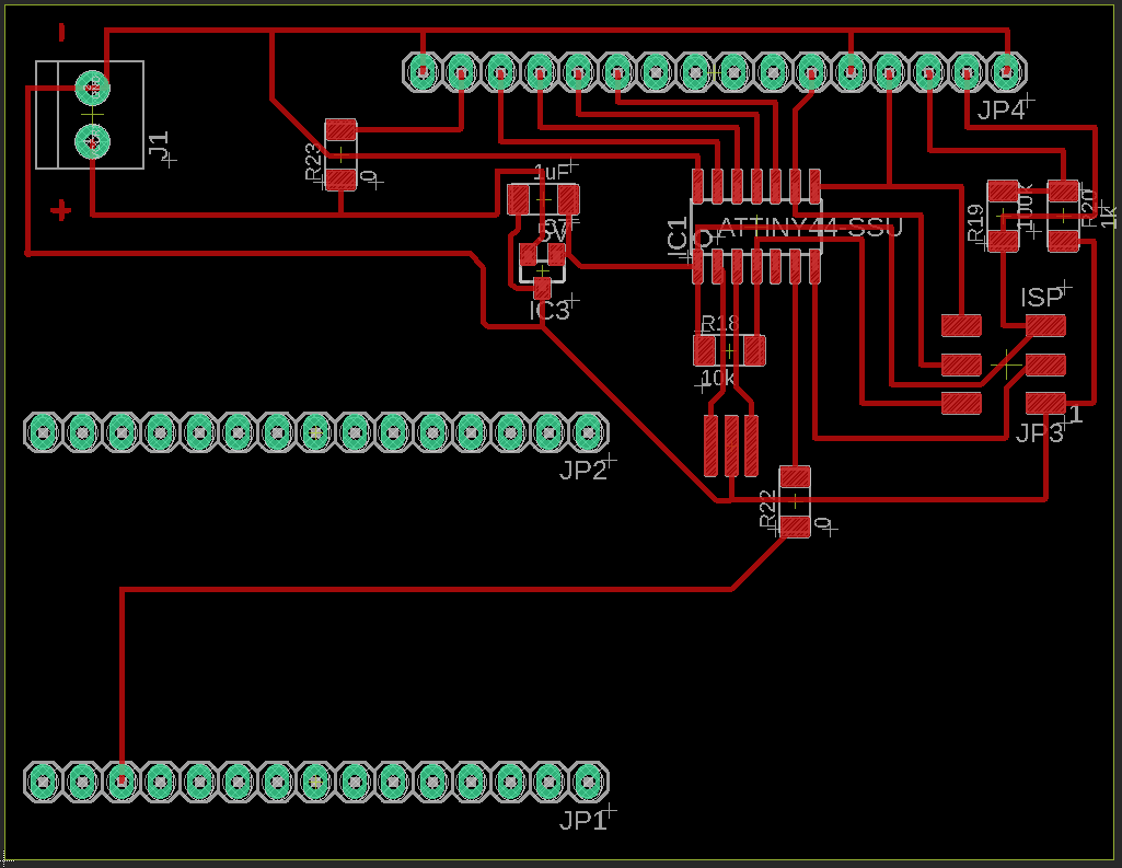
Above, the board schematics for my sensor and display nodes, respectively.
Bill of Materials:
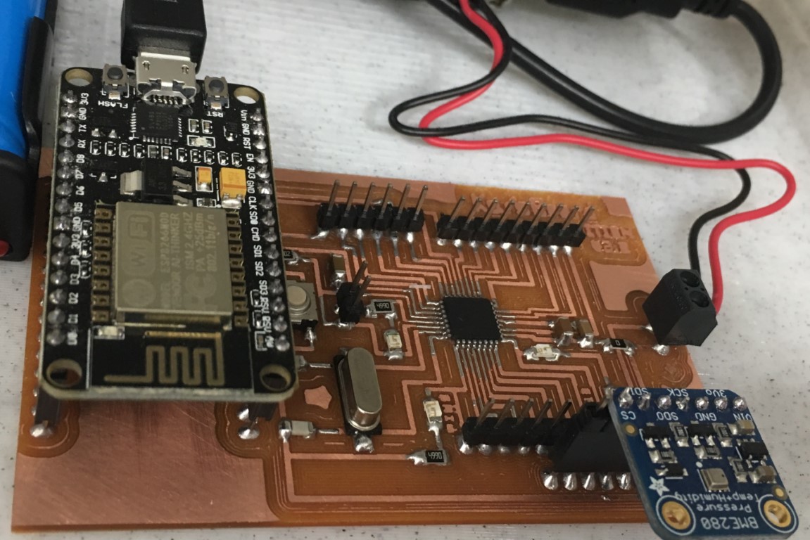
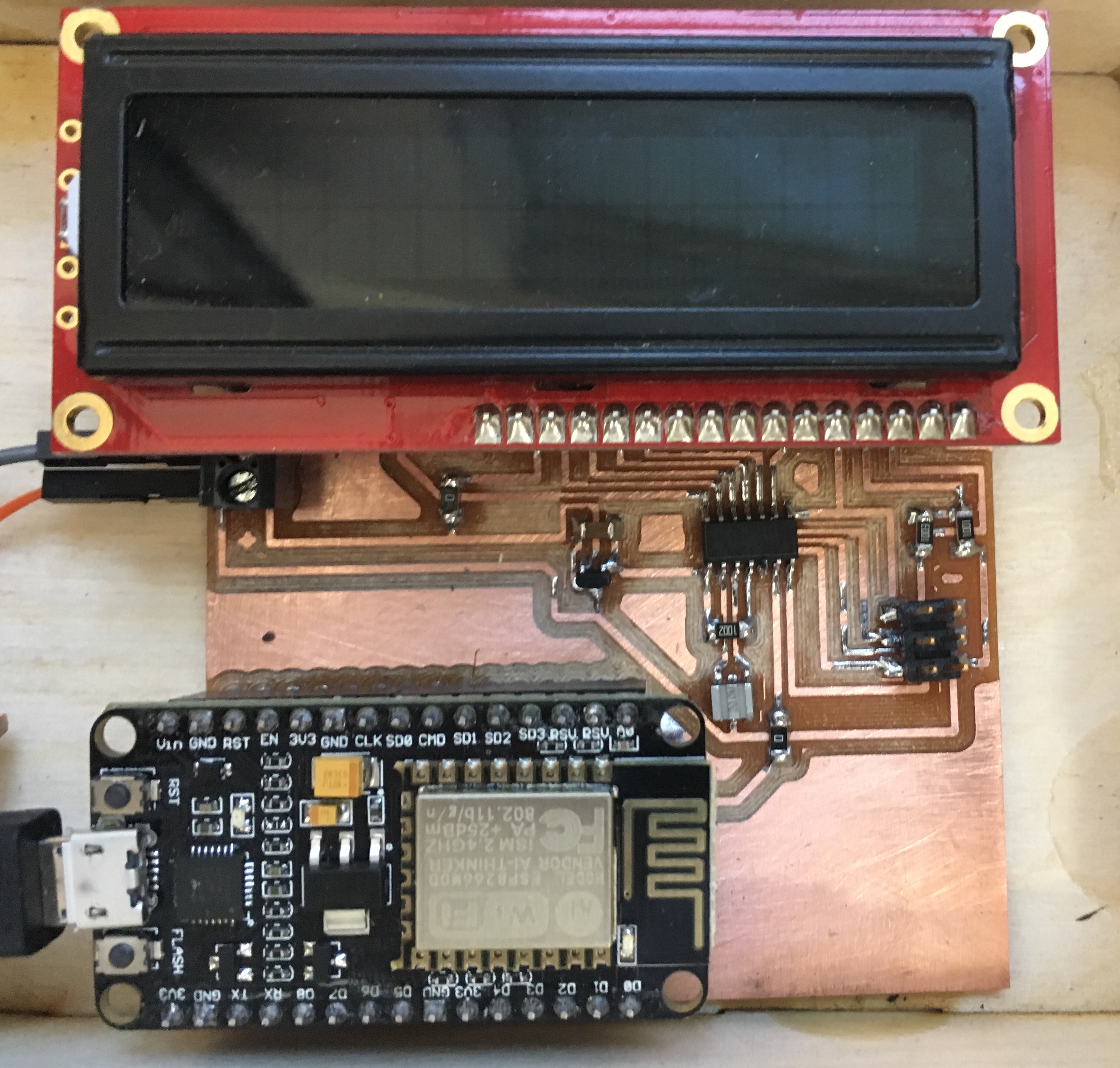
Above, a look at my completed boards, the sensor node and the display node.
Testing
Above, a recording of the serial console output from the BME280 sensor when I tested it.
Power Considerations
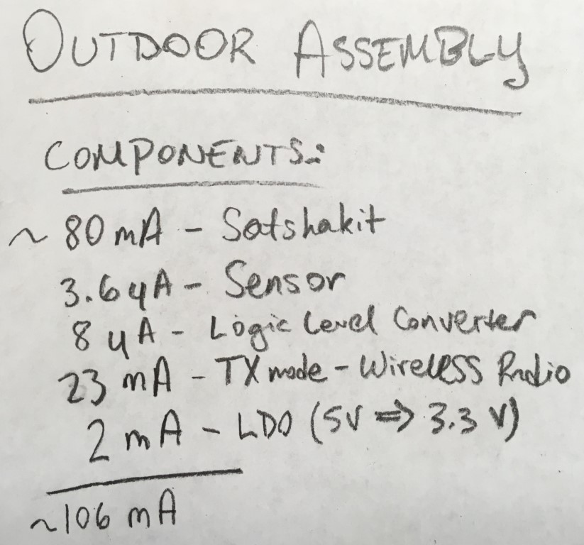
First, I tallied up the average current consumption of each component on my sensor node. (I learned about Quiescent current, or Iq on this forum post; I subsequently found Iq for voltage regulator and other components by looking for Iq on their datasheets)

I then used this information to calculate the average power consumption for an entire day, compared with the worst-case-scenario solar exposure for one day in my region. I found this info on this Solar exposure map. With this info, I decided that a 6V 4.5W solar panel, paired with a 3.7V 18650 battery (which has a similar width to, but is longer than a standard AA battery) with 2500mAh of capacity, and a solar charge controller (so that I would not overcharge/overdrain the battery and potentially damage my electronics) would be an ideal power supply for my outdoor unit. Being solar powered allows the outdoor unit to be placed further away from a building, which provides more accurate sensor readings.
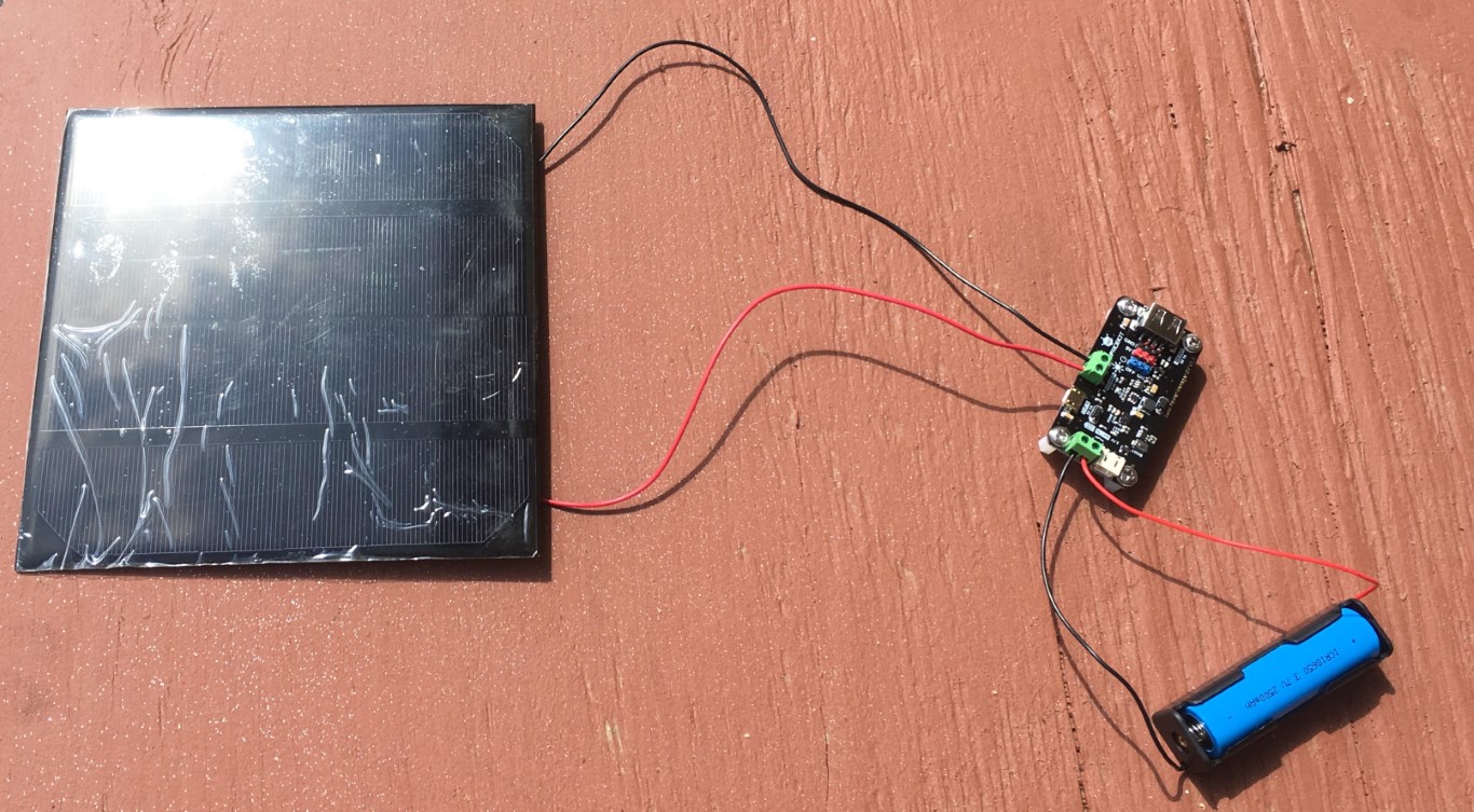
Above, my solar setup outside for testing.
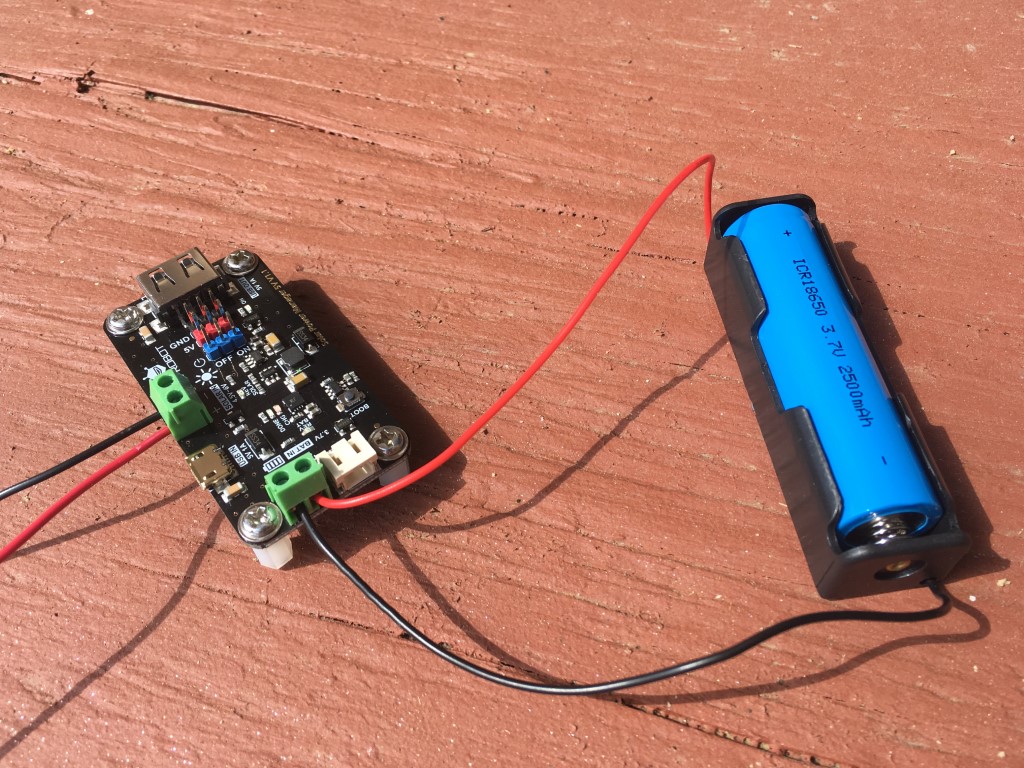
A closer look at the charge controller and the battery. The controller regulates the charge current going to the battery and also provides output in USB and pins as needed. For my project, I’ll be using the pins to connect to my sensor board.
I found this Solar Panel Angle
Wireless Networking Trouble
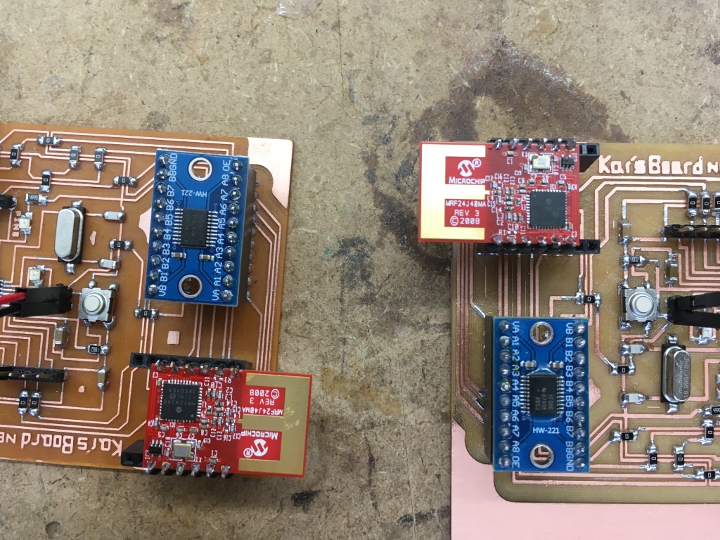
I have been using karlp’s MRF24J40 Arduino library that is used in many Arduino projects with the MRF24J40 wireless modules that I’ve seen on the web. I had been running various iterations of sample code found within the library’s examples and elsewhere. To do so, I basically keept the PAN ID the same for both boards (which I understand is necessary to connect the two modules) and swapping the sending/receiving addresses between boards. As far as I could tell, both modules were sending data, but neither were receiving each others’ transmissions. At this point, I posted on the Arduino forum to try my luck. You can see my post here. (In the end, the forum did not help :( )
The Setup
The wireless modules on each board is connected to the ATMega328P in the following manner (note that all signals, except for GND and VCC, are routed through a Logic Level Converter to shift the levels from 5V to 3.3V and back again since the wireless module operates on 3.3V; see attached photo & schematics for look at the modules and the LLCs, which are on the top left and bottom left of each board, respectively):
| MRF24J40MA Pin (in numerical order from datasheet) | Satshakit (Arduino Uno) Pin |
|---|---|
| GND | GND |
| RESET | 6 |
| WAKE | 2 |
| INT | 3 |
| SDI | 11 (MOSI) |
| SCK | 13 (SCK) |
| SDO | 12 (MISO) |
| CS | 9 |
| NC | - |
| VIN | VCC (via 3.3V LDO regulator) |
| GND | GND |
| GND | GND |
The Code
I began with the Basic_TwoWay example from the aforementioned library (original .ino file attached for reference), and I changed the pins at the top and the attachInterrupt line to reflect my setup, and then only swapped the addresses for sending/receiving on the two boards. The resulting, modified code:
/**
 * Example code for using a microchip mrf24j40 module to send and receive
 * packets using plain 802.15.4
 * Requirements: 3 pins for spi, 3 pins for reset, chip select and interrupt
 * notifications
 * This example file is considered to be in the public domain
 * Originally written by Karl Palsson, karlp@tweak.net.au, March 2011
 */
#include <SPI.h>
#include <mrf24j.h>

const int pin_reset = 6; // UPDATED for my setup!!
const int pin_cs = 9; // UPDATED for my setup!!
const int pin_interrupt = 3; // UPDATED for my setup!!

Mrf24j mrf(pin_reset, pin_cs, pin_interrupt);

long last_time;
long tx_interval = 1000;

void setup() {
  Serial.begin(9600);

  mrf.reset();
  mrf.init();

  mrf.set_pan(0xcafe);
  // 0xcafe is our PAN (common ID)
  mrf.address16_write(0x4202); // CHANGE DEPENDING ON BOARD --> 0x4201 is address on display, 0x4202 on sensor

  // uncomment if you want to receive any packet on this channel
  //mrf.set_promiscuous(true);

  // uncomment if you want to enable PA/LNA external control
  //mrf.set_palna(true);

  // uncomment if you want to buffer all PHY Payload
  //mrf.set_bufferPHY(true);

  attachInterrupt(1, interrupt_routine, CHANGE); // UPDATED for my setup!! --> interrupt 0 equivalent to pin 3 (INT1) on ATmega328
  last_time = millis();
  interrupts();
}

void interrupt_routine() {
    mrf.interrupt_handler(); // mrf24 object interrupt routine
}

void loop() {
    mrf.check_flags(&handle_rx, &handle_tx);
    unsigned long current_time = millis();
    if (current_time - last_time > tx_interval) {
        last_time = current_time;
        Serial.println("txxxing...");
        mrf.send16(0x4201, "abcd"); // CHANGE DEPENDING ON BOARD --> should be opposite of address stated in mrf.address16_write above ^^^
    }
}

void handle_rx() {
    Serial.print("received a packet ");Serial.print(mrf.get_rxinfo()->frame_length, DEC);Serial.println(" bytes long");

    if(mrf.get_bufferPHY()){
      Serial.println("Packet data (PHY Payload):");
      for (int i = 0; i < mrf.get_rxinfo()->frame_length; i++) {
          Serial.print(mrf.get_rxbuf()[i]);
      }
    }

    Serial.println("\r\nASCII data (relevant data):");
    for (int i = 0; i < mrf.rx_datalength(); i++) {
        Serial.write(mrf.get_rxinfo()->rx_data[i]);
    }

    Serial.print("\r\nLQI/RSSI=");
    Serial.print(mrf.get_rxinfo()->lqi, DEC);
    Serial.print("/");
    Serial.println(mrf.get_rxinfo()->rssi, DEC);
}

void handle_tx() {
    if (mrf.get_txinfo()->tx_ok) {
        Serial.println("TX went ok, got ack");
    } else {
        Serial.print("TX failed after ");Serial.print(mrf.get_txinfo()->retries);Serial.println(" retries\n");
    }
}
When I ran this code on one Satshakit and run the same code with swapped addresses on the other Satshakit and open serial monitor for one of the boards, I only get the “txxxing…” message. I was uncertain as to whether the modules are even sending anything at all (or how I could check that they are properly functioning) or why they weren’t receiving each others’ messages. I also un-commented the following line:
mrf.set_promiscuous(true)
which the comment preceding it indicated should show any message on the same channel, but to no avail.
I found another similar library here that has a neat ChannelScanner example that would at least help me figure out if the modules are functioning. However, none of the examples from that library include syntax that showed me how to modify the defined SPI pins, which I needed to change to match my setup.
I also found the following code here that I modified for my setup and tested (webpage is in Portuguese, but I used Google Translate to view it, which is how I found the link for the code) (also note that you have to change the definition of BASE from true to false and vice versa when running the code on the two boards):
#include <SPI.h>
#include <mrf24j.h>

// Defines if the module is the base or the terminal
#define BASE true

// Defines if PA/LNA control is activated
#define PA_LNA true

// Pin definitions
const int pin_reset = 6;
const int pin_cs = 9;
const int pin_interrupt = 3;

// Network addresses
word panId = 0xcafe;
word localAddr;
word destAddr;

// Transmission delay, higher causes less collisions
int txDelay = 20;

// Transmission period tracking
unsigned int interval = 2000;
unsigned long periodStart;

// Packet data
struct packet {
  int sequenceNumber;
  int packetsSent;
  int packetsReceived;
  int rssi;
  int lqi;
} rxPacket, txPacket;

// Packet counters
int packetsSent = 0;
int packetsReceived = 0;

// RSSI and LQI sums for the current period
unsigned long rssiSum = 0;
unsigned long lqiSum = 0;

Mrf24j mrf(pin_reset, pin_cs, pin_interrupt);

void setup() {
  word addr;

  Serial.begin(115200);

  delay(1000);

  // Initialize module
  mrf.init();

  // Delay to let RF stabilize
  delay(1);

  // Configure module as base or node
  if (BASE) {
    // Set to coordinator
    mrf.write_short(0x00, 0x0C);
    localAddr = 0x6001;
    destAddr = 0x6002;
  } else {
    localAddr = 0x6002;
    destAddr = 0x6001;
  }

  // Configure PA_LNA control
  mrf.set_palna(PA_LNA);

  // Try to write and then read back the PAN ID
  mrf.set_pan(panId);
  panId = mrf.get_pan();
  Serial.print("\nPAN ID: 0x");
  Serial.print(panId, HEX);
  Serial.print("\n");

  // Try to write and then read back the module address
  mrf.address16_write(localAddr);
  addr = mrf.address16_read();
  Serial.print("Address: 0x");
  Serial.print(addr, HEX);
  Serial.print("\n");

  // Print some register values for debugging
  byte reg;

  reg = mrf.read_short(0x00);
  Serial.print("RXMCR: 0x");
  Serial.print(reg, HEX);
  Serial.print("\n");

  reg = mrf.read_short(0x11);
  Serial.print("TXMCR: 0x");
  Serial.print(reg, HEX);
  Serial.print("\n");

  reg = mrf.read_short(0x10);
  Serial.print("ORDER: 0x");
  Serial.print(reg, HEX);
  Serial.print("\n");

  reg = mrf.read_short(0x0D);
  Serial.print("RXFLUSH: 0x");
  Serial.print(reg, HEX);
  Serial.print("\n");

  reg = mrf.read_long(0x200);
  Serial.print("RXCON0: 0x");
  Serial.print(reg, HEX);
  Serial.print("\n");

  reg = mrf.read_short(0x32);
  Serial.print("INTCON: 0x");
  Serial.print(reg, HEX);
  Serial.print("\n");

  // Initialize transmission period start time
  periodStart = millis();
}

void loop() {
  int lqi = 0;
  int rssi = 0;

  // Check if messages have been received
  if (receivePacket(&rxPacket, &lqi, &rssi)) {
    packetsReceived++;
    rssiSum += rssi;
    lqiSum += lqi;
  }

  // Send packet to destination
  sendPacket(destAddr, &txPacket);
  packetsSent++;

  // Check for end of transmission period
  if (millis() - periodStart >= interval) {
    // Update data to be transmitted
    txPacket.packetsSent = packetsSent;
    txPacket.packetsReceived = packetsReceived;
    if (packetsReceived > 0) {
      txPacket.rssi = rssiSum / packetsReceived;
      txPacket.lqi = lqiSum / packetsReceived;
    } else {
      txPacket.rssi = 0;
      txPacket.lqi = 0;
    }

    // Reset received packet if no packets received
    if (packetsReceived == 0) {
      rxPacket.packetsSent = 0;
      rxPacket.packetsReceived = 0;
      rxPacket.rssi = 0;
      rxPacket.lqi = 0;
    }

    // Print data
    Serial.println();
    Serial.println("Local:");
    printPacket(txPacket);
    Serial.println("Remote:");
    printPacket(rxPacket);

    // Restart reception period
    packetsSent = 0;
    packetsReceived = 0;
    rssiSum = 0;
    lqiSum = 0;
    periodStart = millis();
  }

  // Delay until next transmission
  if (txDelay > 0) {
    delay(txDelay);
  }
}

void printPacket(struct packet p) {
  Serial.print("  Packets sent: ");
  Serial.println(p.packetsSent);
  Serial.print("  Packets received: ");
  Serial.println(p.packetsReceived);
  Serial.print("  Packet loss: ");
  if (p.packetsSent > 0 && p.packetsReceived > 0) {
    Serial.print(100 * (p.packetsSent - p.packetsReceived) / p.packetsSent);
    Serial.println("%");
  } else {
    Serial.println("-");
  }
  Serial.print("  RSSI: ");
  Serial.println(p.rssi);
  Serial.print("  LQI: ");
  Serial.println(p.lqi);
}

void sendPacket(word addr, struct packet* p) {
  char buf[128];
  p->sequenceNumber++;
  sprintf(buf, "%d,%d,%d,%d,%d", p->sequenceNumber, p->packetsSent, p->packetsReceived, p->rssi, p->lqi);
  mrf.send16(addr, buf);
}

boolean receivePacket(struct packet* p, int* lqi, int* rssi) {
  char buf[128];
  int frameSize;
  int i;

  // Check RXIF in INTSTAT
  if (mrf.read_short(0x31) & 0x08) {
    // Disable interrupts and receiver
    noInterrupts();
    mrf.write_short(0x39, 0x04);

    // Packet received, get the number of bytes
    frameSize = mrf.read_long(0x300);

    // Copy the message bytes into the user buffer
    for (i = 0; i < (frameSize - 11); i++) {
      buf[i] = mrf.read_long(0x301 + 9 + i);
    }
    buf[i] = '\0';

    // Get link quality indicator
    if (lqi) {
      *lqi = mrf.read_long(0x301 + 9 + i + 2);
    }

    // Get signal strength
    if (rssi) {
      *rssi = mrf.read_long(0x301 + 9 + i + 3);
    }

    // Flush the reception buffer, re-enable interrupts and receiver
    mrf.write_short(0x0D, 0x01);
    mrf.write_short(0x39, 0x00);
    interrupts();

    // Wait until RXIF is cleared (takes a while)
    while(mrf.read_short(0x31) & 0x08);

    p->sequenceNumber = atoi(strtok(buf, ","));
    p->packetsSent = atoi(strtok(NULL, ","));
    p->packetsReceived = atoi(strtok(NULL, ","));
    p->rssi = atoi(strtok(NULL, ","));
    p->lqi = atoi(strtok(NULL, ","));

    return true;
  }

  return false;
}
When I opened serial monitor for each board, this is what I got:
Local:
  Packets sent: 96
  Packets received: 0
  Packet loss: -
  RSSI: 0
  LQI: 0
Remote:
  Packets sent: 0
  Packets received: 0
  Packet loss: -
  RSSI: 0
  LQI: 0
I was concerned. Was my setup incorrect or unfeasible? Is there a way to modify the SPI pins used by the SPI library in the ChannelScanner code to match the pins I use without changing base definitions of the entire library (I couldn’t change the design of my board at this point without significant work)? How can I see whether the modules are in fact sending data?
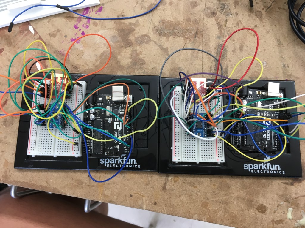
Per the recommendation of Dr. Harris, I breadboarded the modules with stock Arduino UNOs, with my wiring and standard SPI wiring. Unfortunately, this did not resolve any of my issues. Even Dr. Harris did not have any experience with these modules, nor is there much documentation or support. He helped me investigate alternative options, which is when we stumbled upon using ESP8266 WiFi modules as wireless serial bridges.
ESP8266 WiFi modules
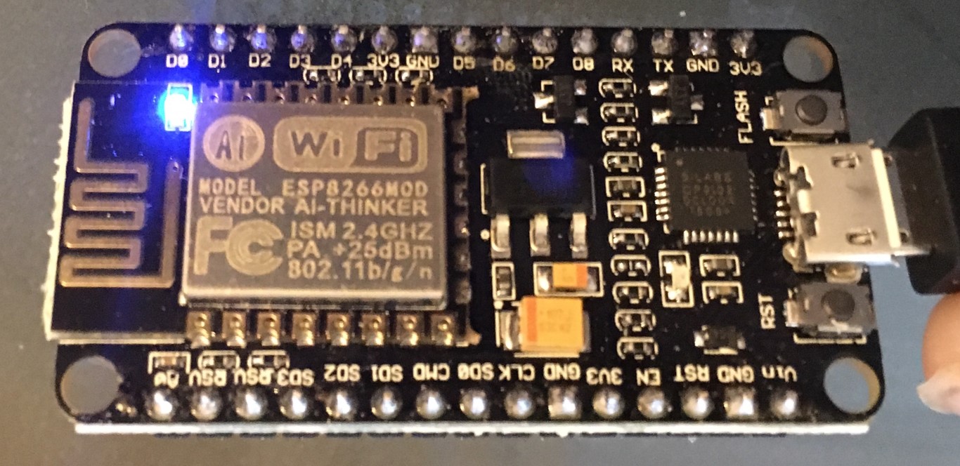
Flashing the modules
Following tutorials, including this one from Adafruit, I downloaded CP210x USB to UART Bridge VCP Drivers here, commissioned a custom build of the NodeMCU firmeware from here, and the NodeMCU PyFlasher from the GitHub & followed instructions found here to flash my modules with PyFlasher.
I selected the COM port that the device was on, selected the filepath of the firmware build, and used a baud rate of 921600. I got the following console output:
Command: esptool.py --port COM20 --baud 921600 --after no_reset write_flash --flash_mode dio 0x00000 C:\Users\LENOVO USER\Downloads\nodemcu-master-7-modules-2019-06-14-19-25-21-float.bin

esptool.py v2.6
Serial port COM20
Connecting....
Detecting chip type... ESP8266
Chip is ESP8266EX
Features: WiFi
MAC: b4:e6:2d:69:d0:d5
Uploading stub...
Running stub...
Stub running...
Changing baud rate to 921600
Changed.
Configuring flash size...
Auto-detected Flash size: 4MB
Flash params set to 0x0240
Compressed 434176 bytes to 280929...
Wrote 434176 bytes (280929 compressed) at 0x00000000 in 3.8 seconds (effective 911.2 kbit/s)...
Hash of data verified.

Leaving...
Staying in bootloader.

Firmware successfully flashed. Unplug/replug or reset device
to switch back to normal boot mode.
After I flashed the boards, I replugged them in, and they began blinking as expected. Above, a video of the process.
Next, I downloaded Espressif’s Flash Download Tools and the esp-link firmware from their GitHub page. Once I ran the tool, I selected the ESP8266 tool and carefully followed the esp-link flashing instructions on their GitHub.
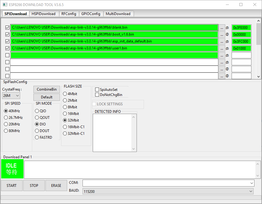
Above, a look at my settings for flashing esp-link for my specific modules. I then selected the COM port that the module was on and clicked Start.
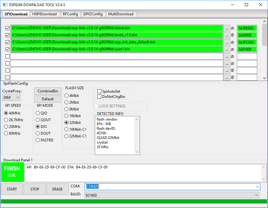
Above, the result of the successful flash.
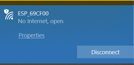
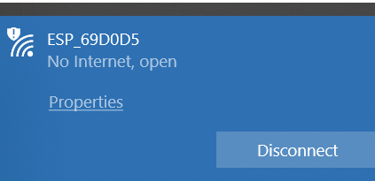
Once I flashed the modules, I plugged one back in, opened my WiFi menu on my PC, and connected to the new network (see above screenshots for the two network names).
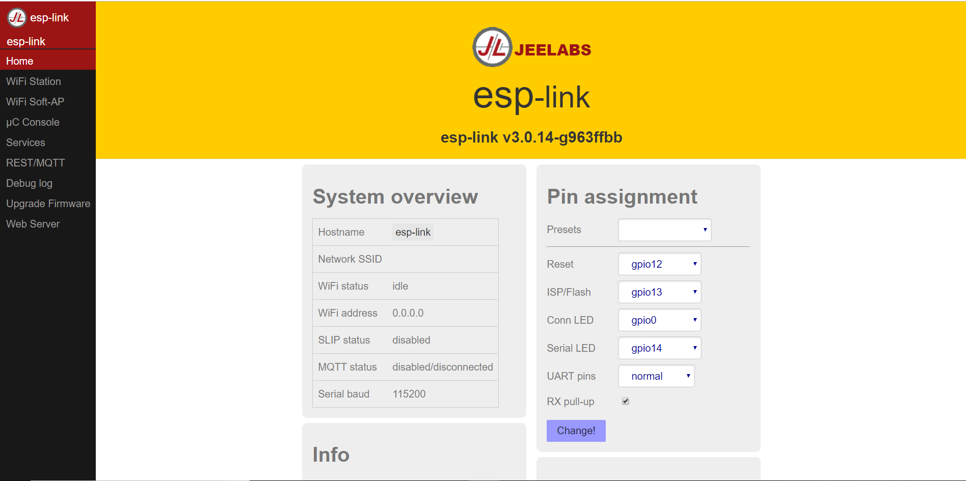
Then, I navigated to http://192.168.4.1, which brought up the above splash page.
Wireless hello world
Next, I created a simple hello world program for a stock Arduino UNO to send via serial to the WiFi module, as seen below:
void setup() {
  // put your setup code here, to run once:
Serial.begin(115200);
}

void loop() {
  // put your main code here, to run repeatedly:
Serial.print("Hello world");
}
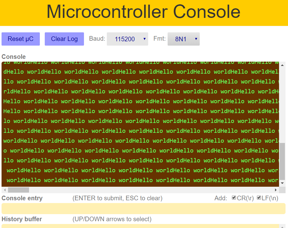
Then, I connected the TX/RX pins on the UNO to the RX/TX pins on the ESP, fired up the module again, went to the Microcontroller Console on the ESP’s page, and watched with delight as the data appeared!
Communicating between modules
After I did all of this, I realized that to do a connection between two ESPs, I needed to stick with the NodeMCU firmware and upload code to the modules via the Arduino IDE. Once I re-flashed NodeMCU onto the modules, I visited the GitHub to download the ESP8266WiFi library (I used DownGit to download the single library that I wanted instead of downloading the entire repo, which includes multiple libraries) and followed the Readme to install the boards via Boards Manager on the IDE.
Then, I found Station & Access Point code on this Instructable, which was crucial to this project.
To start, I simply changed the SSID & password of the network being created.
My AP code:
/*  Accesspoint - station communication without router
 *  see: https://github.com/esp8266/Arduino/blob/master/doc/esp8266wifi/soft-access-point-class.rst
 *       https://github.com/esp8266/Arduino/blob/master/doc/esp8266wifi/soft-access-point-examples.rst
 *       https://github.com/esp8266/Arduino/issues/504
 *  Works with: station_bare_01.ino
 */


#include <ESP8266WiFi.h>

WiFiServer server(80);
IPAddress IP(192,168,4,15);
IPAddress mask = (255, 255, 255, 0);

byte ledPin = 2;

void setup() {
  Serial.begin(9600);
  WiFi.mode(WIFI_AP);
  WiFi.softAP("WS_AP", "WS_fab2019"); // SSID & password
  WiFi.softAPConfig(IP, IP, mask);
  server.begin();
  pinMode(ledPin, OUTPUT);
  Serial.println();
  Serial.println("accesspoint_bare_01.ino");
  Serial.println("Server started.");
  Serial.print("IP: ");     Serial.println(WiFi.softAPIP());
  Serial.print("MAC:");     Serial.println(WiFi.softAPmacAddress());
}

void loop() {
  WiFiClient client = server.available();
  if (!client) {return;}
  digitalWrite(ledPin, LOW);
  String request = client.readStringUntil('\r');
  Serial.println("********************************");
  Serial.println("From the station: " + request);
  client.flush();
  Serial.print("Byte sent to the station: ");
  Serial.println(client.println(request + "ca" + "\r"));
  digitalWrite(ledPin, HIGH);
}
My Station code:
/*  Accesspoint - station communication without router
 *  see: https://github.com/esp8266/Arduino/blob/master/doc/esp8266wifi/station-class.rst
 *  Works with: accesspoint_bare_01.ino
 */

#include <ESP8266WiFi.h>

byte ledPin = 2;
char ssid[] = "WS_AP";           // SSID of your AP
char pass[] = "WS_fab2019";         // password of your AP

IPAddress server(192,168,4,15);     // IP address of the AP
WiFiClient client;

void setup() {
  Serial.begin(9600);
  WiFi.mode(WIFI_STA);
  WiFi.begin(ssid, pass);           // connects to the WiFi AP
  Serial.println();
  Serial.println("Connection to the AP");
  while (WiFi.status() != WL_CONNECTED) {
    Serial.print(".");
    delay(500);
  }
  Serial.println();
  Serial.println("Connected");
  Serial.println("station_bare_01.ino");
  Serial.print("LocalIP:"); Serial.println(WiFi.localIP());
  Serial.println("MAC:" + WiFi.macAddress());
  Serial.print("Gateway:"); Serial.println(WiFi.gatewayIP());
  Serial.print("AP MAC:"); Serial.println(WiFi.BSSIDstr());
  pinMode(ledPin, OUTPUT);
}

void loop() {
  client.connect(server, 80);
  digitalWrite(ledPin, LOW);
  Serial.println("********************************");
  Serial.print("Byte sent to the AP: ");
  Serial.println(client.print("Anyo\r"));
  String answer = client.readStringUntil('\r');
  Serial.println("From the AP: " + answer);
  client.flush();
  digitalWrite(ledPin, HIGH);
  client.stop();
  delay(2000);
}
You can see the aforementioned code working in the above video.
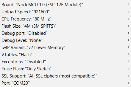
I used the above board settings in the IDE based on the manufacturer’s specifications and uploaded the AP/Station codes to the AP & Station modules, respectively.
Functional code
Once I successfully tested this interface, I worked for a while to format the code files to suit my project.
As I began sending sensor data from my sensor node through the network, I began to see a disconnect. Due to the devices running on separate clocks, the transfer of data was not synced. Luckily, this Arduino forum post helped me figure out how to use start and stop characters (angled brackets in my case) to recognize an entire string of data. You can see the jumbled data in the above video.
As soon as I implemented this, the data transferred much smoother, as seen in the above video.
My Sensor node code:
/***************************************************************************
  This is a library for the BME280 humidity, temperature & pressure sensor

  Designed specifically to work with the Adafruit BME280 Breakout
  ----> http://www.adafruit.com/products/2650

  These sensors use I2C or SPI to communicate, 2 or 4 pins are required
  to interface. The device's I2C address is either 0x76 or 0x77.

  Adafruit invests time and resources providing this open source code,
  please support Adafruit andopen-source hardware by purchasing products
  from Adafruit!

  Written by Limor Fried & Kevin Townsend for Adafruit Industries.
  BSD license, all text above must be included in any redistribution
 ***************************************************************************/

#include <Wire.h>
#include <SPI.h>
#include <Adafruit_Sensor.h>
#include <Adafruit_BME280.h>

#define BME_SCK 13
#define BME_MISO 12
#define BME_MOSI 11
#define BME_CS 10

#define SEALEVELPRESSURE_HPA (1013.25)

float TempInC = 0.0;
float TempInF = 0.0;
float Pressure = 0.0;
float Humidity = 0.0;

//Adafruit_BME280 bme; // I2C
//Adafruit_BME280 bme(BME_CS); // hardware SPI
Adafruit_BME280 bme(BME_CS, BME_MOSI, BME_MISO, BME_SCK); // software SPI

unsigned long delayTime;

void setup() {
    Serial.begin(9600);
    // Serial.println(F("BME280 test"));

    bool status;

    // default settings
    // (you can also pass in a Wire library object like &Wire2)
    status = bme.begin();
    if (!status) {
        Serial.println("Could not find a valid BME280 sensor, check wiring!");
        while (1);
    }

   // Serial.println("-- Default Test --");
    delayTime = 1000;

   // Serial.println();
}


void loop() {
    WeatherVals();
    printValues();
    delay(delayTime);
}

void WeatherVals() {
  TempInC = bme.readTemperature();
  TempInF = ((TempInC * 1.8) + 32);
  Pressure = (bme.readPressure() / 100.0F);
  Humidity = bme.readHumidity();
}

void printValues() {

    /* String WeatherData[] = String(TempInF,Pressure,Humidity);
    Serial.println(WeatherData + '\r');*/
    // Serial.println(TempInF + ',' + Pressure + ',' + Humidity + '\r'); // create string manually
    String WeatherData1 = '<' + String(TempInF, 2);
    // String WeatherData2 = WeatherData1;
    String WeatherData2 = WeatherData1 + String(Pressure, 2) + ' ';
    // String WeatherData4 = WeatherData3;
    String WeatherData3 = WeatherData2 + String(Humidity, 0);
    String WeatherData = WeatherData3 + '>';
    Serial.println(WeatherData + '\r');
    /*Serial.print("Temperature = ");
    Serial.print(bme.readTemperature());
    Serial.println(" *C");

    Serial.print("Pressure = ");

    Serial.print(bme.readPressure() / 100.0F);
    Serial.println(" hPa");

    Serial.print("Approx. Altitude = ");
    Serial.print(bme.readAltitude(SEALEVELPRESSURE_HPA));
    Serial.println(" m");

    Serial.print("Humidity = ");
    Serial.print(bme.readHumidity());
    Serial.println(" %");

    Serial.println(); */
}
My Station (ESP module connected to my Sensor Node) code:
/*  Accesspoint - station communication without router
 *  see: https://github.com/esp8266/Arduino/blob/master/doc/esp8266wifi/station-class.rst
 *  Works with: accesspoint_bare_01.ino
 */

#include <ESP8266WiFi.h>

byte ledPin = 2;
char ssid[] = "WS_AP";           // SSID of your AP
char pass[] = "WS_fab2019";         // password of your AP

const byte numChars = 32;
char receivedChars[numChars];

boolean newData = false;

IPAddress server(192,168,4,15);     // IP address of the AP


void setup() {
  Serial.begin(9600);
  WiFi.mode(WIFI_STA);
  WiFi.begin(ssid, pass);           // connects to the WiFi AP
  // Serial.println();
  // Serial.println("Connection to the AP");
  while (WiFi.status() != WL_CONNECTED) {
    // Serial.print(".");
    delay(500);
  }
  /* Serial.println();
  Serial.println("Connected");
  Serial.println("station_bare_01.ino");
  Serial.print("LocalIP:"); Serial.println(WiFi.localIP());
  Serial.println("MAC:" + WiFi.macAddress());
  Serial.print("Gateway:"); Serial.println(WiFi.gatewayIP());
  Serial.print("AP MAC:"); Serial.println(WiFi.BSSIDstr());
  pinMode(ledPin, OUTPUT); */
}

void loop() {
  recvWithStartEndMarkers();
  // showNewData();
  WiFiClient client;
  client.connect(server, 80);
  // digitalWrite(ledPin, LOW);
  // Serial.println("********************************");
  // Serial.print("Byte sent to the AP: ");
  String WeatherData = receivedChars;
  client.print(WeatherData + '\r');
  // String answer = client.readStringUntil('\r');
  // Serial.println("From the AP: " + answer);
  client.flush();
  // digitalWrite(ledPin, HIGH);
  client.stop();
  delay(1000);
  newData = false;
}

void recvWithStartEndMarkers() {
    static boolean recvInProgress = false;
    static byte ndx = 0;
    char startMarker = '<';
    char endMarker = '>';
    char rc;

    while (Serial.available() > 0 && newData == false) {
        rc = Serial.read();

        if (recvInProgress == true) {
            if (rc != endMarker) {
                receivedChars[ndx] = rc;
                ndx++;
                if (ndx >= numChars) {
                    ndx = numChars - 1;
                }
            }
            else {
                receivedChars[ndx] = '\0'; // terminate the string
                recvInProgress = false;
                ndx = 0;
                newData = true;
            }
        }

        else if (rc == startMarker) {
            recvInProgress = true;
        }
    }
}

/* void showNewData() {
    if (newData == true) {
        // Serial.print("This just in ... ");
        // Serial.println(receivedChars);
        // newData = false;
    }
} */
My Access Point (other ESP module) code:
/*  Accesspoint - station communication without router
 *  see: https://github.com/esp8266/Arduino/blob/master/doc/esp8266wifi/soft-access-point-class.rst
 *       https://github.com/esp8266/Arduino/blob/master/doc/esp8266wifi/soft-access-point-examples.rst
 *       https://github.com/esp8266/Arduino/issues/504
 *  Works with: station_bare_01.ino
 */


#include <ESP8266WiFi.h>

WiFiServer server(80);
IPAddress IP(192,168,4,15);
IPAddress mask = (255, 255, 255, 0);

const byte numChars = 32;
char receivedChars[numChars];
char DataInChar[numChars];

boolean newData = false;

// byte ledPin = 2;

void setup() {
  Serial.begin(9600);
  WiFi.mode(WIFI_AP);
  WiFi.softAP("WS_AP", "WS_fab2019"); // SSID & password
  WiFi.softAPConfig(IP, IP, mask);
  server.begin();
  // pinMode(ledPin, OUTPUT);
  /* Serial.println();
  Serial.println("accesspoint_bare_01.ino");
  Serial.println("Server started.");
  Serial.print("IP: ");     Serial.println(WiFi.softAPIP());
  Serial.print("MAC:");     Serial.println(WiFi.softAPmacAddress());*/
}

void loop() {
  WiFiClient client = server.available();
  if (!client) {return;}
  // recvWithStartEndMarkers();
  // showNewData();
  // digitalWrite(ledPin, LOW);
  String WeatherData = client.readStringUntil('\r');
  // Serial.println("********************************");
  Serial.println(WeatherData + '\r');
  client.flush();
  // Serial.print("Byte sent to the station: ");
  // Serial.println(client.println(request + "ca" + "\r"));
  // digitalWrite(ledPin, HIGH);
  delay(1000);
  newData = false;
}

/* void recvWithStartEndMarkers() {
    static boolean recvInProgress = false;
    static byte ndx = 0;
    char startMarker = '<';
    char endMarker = '>';
    char rc[numChars];

    while (WiFi.status() == WL_CONNECTED && newData == false) {
        WiFiClient client = server.available(); // duplicated line to satisfy client in below line
        String StrToConvert = client.readStringUntil('\r');
        StrToConvert.toCharArray(DataInChar, 32);
        rc = DataInChar;

        if (recvInProgress == true) {
            if (rc != endMarker) {
                receivedChars[ndx] = rc;
                ndx++;
                if (ndx >= numChars) {
                    ndx = numChars - 1;
                }
            }
            else {
                receivedChars[ndx] = '\0'; // terminate the string
                recvInProgress = false;
                ndx = 0;
                newData = true;
            }
        }

        else if (rc == startMarker) {
            recvInProgress = true;
        }
    }
} */

/* void showNewData() {
    if (newData == true) {
        // Serial.print("This just in ... ");
        // Serial.println(receivedChars);
        // newData = false;
    }
} */
At the time of development, I still had my LCD board (run by a Tiny44) on the same PCB as my Display Node board, which is now deprecated because the ESP AP node can send the weather data straight to the LCD board via serial. To test, I simply wired the TX pin of the AP node to RX of the display board (Satshakit) and ran code that basically turned the display board into a Serial repeater:
void setup() {
  // put your setup code here, to run once:
Serial.begin(9600);
}

void loop() {
  // put your main code here, to run repeatedly:
Serial.println(Serial.read());
}
My display board code:
/*
  LiquidCrystal Library - Serial Input

  Demonstrates the use a 16x2 LCD display.  The LiquidCrystal
  library works with all LCD displays that are compatible with the
  Hitachi HD44780 driver. There are many of them out there, and you
  can usually tell them by the 16-pin interface.

  This sketch displays text sent over the serial port
  (e.g. from the Serial Monitor) on an attached LCD.

  The circuit:
   LCD RS pin to digital pin 12
   LCD Enable pin to digital pin 11
   LCD D4 pin to digital pin 5
   LCD D5 pin to digital pin 4
   LCD D6 pin to digital pin 3
   LCD D7 pin to digital pin 2
   LCD R/W pin to ground
   10K resistor:
   ends to +5V and ground
   wiper to LCD VO pin (pin 3)

  Library originally added 18 Apr 2008
  by David A. Mellis
  library modified 5 Jul 2009
  by Limor Fried (http://www.ladyada.net)
  example added 9 Jul 2009
  by Tom Igoe
  modified 22 Nov 2010
  by Tom Igoe
  modified 7 Nov 2016
  by Arturo Guadalupi

  This example code is in the public domain.

  http://www.arduino.cc/en/Tutorial/LiquidCrystalSerialDisplay

*/

// include the library code:
#include <LiquidCrystal.h>

// initialize the library by associating any needed LCD interface pin
// with the arduino pin number it is connected to
const int rs = 5, en = 4, d4 = 3, d5 = 2, d6 = 1, d7 = 0, RX = 7, TX = 8;
LiquidCrystal lcd(rs, en, d4, d5, d6, d7);

#include <SoftwareSerial.h>
// ***
// *** Define the RX and TX pins. Choose any two
// *** pins that are unused. Try to avoid D0 (pin 5)
// *** and D2 (pin 7) if you plan to use I2C.
// ***
// int RX = 8;   // *** D3, Pin 2
//#define TX    8   // *** D4, Pin 3

// ***
// *** Define the software based serial port. Using the
// *** name Serial so that code can be used on other
// *** platforms that support hardware based serial. On
// *** chips that support the hardware serial, just
// *** comment this line.
// ***
SoftwareSerial mySerial (RX, TX);

void setup() {
  // set up the LCD's number of columns and rows:
  lcd.begin(16, 2);
  // initialize the serial communications:
  mySerial.begin(9600);

      lcd.setCursor(0,0);
    lcd.write("Temp Press Humid");
}

void loop() {
  // int charcount;
  // boolean secondline;
  // if (mySerial.available()) {
   // delay(100);
    // lcd.clear();
    // charcount = 0;
    // secondline = false;
    /* while (mySerial.available() > 0) {
      if (charcount > 15 && secondline == false ) {
        lcd.setCursor(0, 1);
        secondline = true;
      }
      lcd.write(mySerial.read());
      charcount++;
    } */
    lcd.setCursor(0,1);
    lcd.write(mySerial.read());
 //}
  delay(1000);
}
UPDATE: I have had lots of troube with my LCD Display. With the help of the amazing Dr. Harris, we isolated the issue down to SoftwareSerial. Due to this, I had to change my display node from a Tiny44 to a Satshakit so that I could run standard Serial. First, I tested the pinout with a stock Arduino Uno and breadboard, as seen in the above video.
My new display board code:
/*
  LiquidCrystal Library - Hello World

 Demonstrates the use a 16x2 LCD display.  The LiquidCrystal
 library works with all LCD displays that are compatible with the
 Hitachi HD44780 driver. There are many of them out there, and you
 can usually tell them by the 16-pin interface.

 This sketch prints "Hello World!" to the LCD
 and shows the time.

  The circuit:
 * LCD RS pin to digital pin 12
 * LCD Enable pin to digital pin 11
 * LCD D4 pin to digital pin 5
 * LCD D5 pin to digital pin 4
 * LCD D6 pin to digital pin 3
 * LCD D7 pin to digital pin 2
 * LCD R/W pin to ground
 * LCD VSS pin to ground
 * LCD VCC pin to 5V
 * 10K resistor:
 * ends to +5V and ground
 * wiper to LCD VO pin (pin 3)

 Library originally added 18 Apr 2008
 by David A. Mellis
 library modified 5 Jul 2009
 by Limor Fried (http://www.ladyada.net)
 example added 9 Jul 2009
 by Tom Igoe
 modified 22 Nov 2010
 by Tom Igoe
 modified 7 Nov 2016
 by Arturo Guadalupi

 This example code is in the public domain.

 http://www.arduino.cc/en/Tutorial/LiquidCrystalHelloWorld

*/

// include the library code:
#include <LiquidCrystal.h>

// initialize the library by associating any needed LCD interface pin
// with the arduino pin number it is connected to
const int rs = 12, en = 11, d4 = 5, d5 = 4, d6 = 3, d7 = 2;
LiquidCrystal lcd(rs, en, d4, d5, d6, d7);

void setup() {
  // set up the LCD's number of columns and rows:
  lcd.begin(16, 2);

  // Print a message to the LCD.

  Serial.begin(9600);
}

void loop() {
  // set the cursor to column 0, line 1
  // (note: line 1 is the second row, since counting begins with 0):

  // print the number of seconds since reset:
   if (Serial.available()) {
    // wait a bit for the entire message to arrive
//    delay(100);
    // clear the screen
    lcd.clear();
      lcd.print("Temp Press Humid");
    // read all the available characters
    while (Serial.available() > 0) {
      // display each character to the LCD
      lcd.setCursor(0, 1);
      lcd.print(Serial.readStringUntil('\r'));
    }
  }
  //delay(2000);
}
UPDATE #2: A lot has happened since the last update, including many, many hours of troubleshooting. In the end, with the help of Dr. Harris, I used code on my display node that removed a lot of the overhead from the LCD and SoftwareSerial libraries. Additionally, I figured out that at some point during debugging, I changed the Serial rate on all of my boards except the display board to 9800 instead of 9600, which WAS NOT GOOD! However, once I identified this issue, everything went far smoother.
Final Code:
Sensor Node:
/***************************************************************************
  This is a library for the BME280 humidity, temperature & pressure sensor

  Designed specifically to work with the Adafruit BME280 Breakout
  ----> http://www.adafruit.com/products/2650

  These sensors use I2C or SPI to communicate, 2 or 4 pins are required
  to interface. The device's I2C address is either 0x76 or 0x77.

  Adafruit invests time and resources providing this open source code,
  please support Adafruit andopen-source hardware by purchasing products
  from Adafruit!

  Written by Limor Fried & Kevin Townsend for Adafruit Industries.
  BSD license, all text above must be included in any redistribution
 ***************************************************************************/

#include <Wire.h>
#include <SPI.h>
#include <Adafruit_Sensor.h>
#include <Adafruit_BME280.h>

#define BME_SCK 13
#define BME_MISO 12
#define BME_MOSI 11
#define BME_CS 10

#define SEALEVELPRESSURE_HPA (1013.25)

float TempInC = 0.0;
float TempInF = 0.0;
float Pressure = 0.0;
float Humidity = 0.0;

//Adafruit_BME280 bme; // I2C
//Adafruit_BME280 bme(BME_CS); // hardware SPI
Adafruit_BME280 bme(BME_CS, BME_MOSI, BME_MISO, BME_SCK); // software SPI

unsigned long delayTime;

void setup() {
    Serial.begin(9600);
    // Serial.println(F("BME280 test"));

    bool status;

    // default settings
    // (you can also pass in a Wire library object like &Wire2)
    status = bme.begin();
    if (!status) {
        Serial.println("Could not find a valid BME280 sensor, check wiring!");
        while (1);
    }

   // Serial.println("-- Default Test --");
    delayTime = 1000;

   // Serial.println();
}


void loop() {
    WeatherVals();
    printValues();
    delay(delayTime);
}

void WeatherVals() {
  TempInC = bme.readTemperature();
  TempInF = ((TempInC * 1.8) + 32);
  Pressure = (bme.readPressure() / 100.0F);
  Humidity = bme.readHumidity();
}

void printValues() {

    /* String WeatherData[] = String(TempInF,Pressure,Humidity);
    Serial.println(WeatherData + '\r');*/
    // Serial.println(TempInF + ',' + Pressure + ',' + Humidity + '\r'); // create string manually
    String WeatherData1 = '<' + String(TempInF, 2) + ' ';
    // String WeatherData2 = WeatherData1;
    String WeatherData2 = WeatherData1 + String(Pressure, 2) + ' ';
    // String WeatherData4 = WeatherData3;
    String WeatherData3 = WeatherData2 + String(Humidity, 0);
    String WeatherData = WeatherData3 + '>';
    Serial.println(WeatherData + '\r');
    /*Serial.print("Temperature = ");
    Serial.print(bme.readTemperature());
    Serial.println(" *C");

    Serial.print("Pressure = ");

    Serial.print(bme.readPressure() / 100.0F);
    Serial.println(" hPa");

    Serial.print("Approx. Altitude = ");
    Serial.print(bme.readAltitude(SEALEVELPRESSURE_HPA));
    Serial.println(" m");

    Serial.print("Humidity = ");
    Serial.print(bme.readHumidity());
    Serial.println(" %");

    Serial.println(); */
}
Station ESP:
/*  Accesspoint - station communication without router
 *  see: https://github.com/esp8266/Arduino/blob/master/doc/esp8266wifi/station-class.rst
 *  Works with: accesspoint_bare_01.ino
 */

#include <ESP8266WiFi.h>

byte ledPin = 2;
char ssid[] = "WS_AP";           // SSID of your AP
char pass[] = "WS_fab2019";         // password of your AP

const byte numChars = 32;
char receivedChars[numChars];

boolean newData = false;

IPAddress server(192,168,4,15);     // IP address of the AP


void setup() {
  Serial.begin(9600);
  WiFi.mode(WIFI_STA);
  WiFi.begin(ssid, pass);           // connects to the WiFi AP
  // Serial.println();
  // Serial.println("Connection to the AP");
  while (WiFi.status() != WL_CONNECTED) {
    // Serial.print(".");
    delay(500);
  }
  /* Serial.println();
  Serial.println("Connected");
  Serial.println("station_bare_01.ino");
  Serial.print("LocalIP:"); Serial.println(WiFi.localIP());
  Serial.println("MAC:" + WiFi.macAddress());
  Serial.print("Gateway:"); Serial.println(WiFi.gatewayIP());
  Serial.print("AP MAC:"); Serial.println(WiFi.BSSIDstr());
  pinMode(ledPin, OUTPUT); */
}

void loop() {
  recvWithStartEndMarkers();
  // showNewData();
  WiFiClient client;
  client.connect(server, 80);
  // digitalWrite(ledPin, LOW);
  // Serial.println("********************************");
  // Serial.print("Byte sent to the AP: ");
  String WeatherData = receivedChars;
  client.print(WeatherData + '\r');
  // String answer = client.readStringUntil('\r');
  // Serial.println("From the AP: " + answer);
  client.flush();
  // digitalWrite(ledPin, HIGH);
  client.stop();
  delay(1000);
  newData = false;
}

void recvWithStartEndMarkers() {
    static boolean recvInProgress = false;
    static byte ndx = 0;
    char startMarker = '<';
    char endMarker = '>';
    char rc;

    while (Serial.available() > 0 && newData == false) {
        rc = Serial.read();

        if (recvInProgress == true) {
            if (rc != endMarker) {
                receivedChars[ndx] = rc;
                ndx++;
                if (ndx >= numChars) {
                    ndx = numChars - 1;
                }
            }
            else {
                receivedChars[ndx] = '\0'; // terminate the string
                recvInProgress = false;
                ndx = 0;
                newData = true;
            }
        }

        else if (rc == startMarker) {
            recvInProgress = true;
        }
    }
}

/* void showNewData() {
    if (newData == true) {
        // Serial.print("This just in ... ");
        // Serial.println(receivedChars);
        // newData = false;
    }
} */
AP ESP:
/*  Accesspoint - station communication without router
 *  see: https://github.com/esp8266/Arduino/blob/master/doc/esp8266wifi/soft-access-point-class.rst
 *       https://github.com/esp8266/Arduino/blob/master/doc/esp8266wifi/soft-access-point-examples.rst
 *       https://github.com/esp8266/Arduino/issues/504
 *  Works with: station_bare_01.ino
 */


#include <ESP8266WiFi.h>

WiFiServer server(80);
IPAddress IP(192,168,4,15);
IPAddress mask = (255, 255, 255, 0);

const byte numChars = 32;
char receivedChars[numChars];
char DataInChar[numChars];

boolean newData = false;

// byte ledPin = 2;

void setup() {
  Serial.begin(9600);
  WiFi.mode(WIFI_AP);
  WiFi.softAP("WS_AP", "WS_fab2019"); // SSID & password
  WiFi.softAPConfig(IP, IP, mask);
  server.begin();
  // pinMode(ledPin, OUTPUT);
  /* Serial.println();
  Serial.println("accesspoint_bare_01.ino");
  Serial.println("Server started.");
  Serial.print("IP: ");     Serial.println(WiFi.softAPIP());
  Serial.print("MAC:");     Serial.println(WiFi.softAPmacAddress());*/
}

void loop() {
  WiFiClient client = server.available();
  if (!client) {return;}
  // recvWithStartEndMarkers();
  // showNewData();
  // digitalWrite(ledPin, LOW);
  String WeatherData = client.readStringUntil('\r');
  // Serial.println("********************************");
  unsigned int lastStringLength = WeatherData.length();

  for(int i=lastStringLength; i<17; i++){
    WeatherData= WeatherData+' ';
  }

  //print each character in the string at a time
   for(int j=0; j<17; j++){
    Serial.println(WeatherData.charAt(j));
    delay(100);
  }
//  Serial.println(WeatherData + '\r');
  client.flush();
  // Serial.print("Byte sent to the station: ");
  // Serial.println(client.println(request + "ca" + "\r"));
  // digitalWrite(ledPin, HIGH);
  delay(1000);
  newData = false;
}

/* void recvWithStartEndMarkers() {
    static boolean recvInProgress = false;
    static byte ndx = 0;
    char startMarker = '<';
    char endMarker = '>';
    char rc[numChars];

    while (WiFi.status() == WL_CONNECTED && newData == false) {
        WiFiClient client = server.available(); // duplicated line to satisfy client in below line
        String StrToConvert = client.readStringUntil('\r');
        StrToConvert.toCharArray(DataInChar, 32);
        rc = DataInChar;

        if (recvInProgress == true) {
            if (rc != endMarker) {
                receivedChars[ndx] = rc;
                ndx++;
                if (ndx >= numChars) {
                    ndx = numChars - 1;
                }
            }
            else {
                receivedChars[ndx] = '\0'; // terminate the string
                recvInProgress = false;
                ndx = 0;
                newData = true;
            }
        }

        else if (rc == startMarker) {
            recvInProgress = true;
        }
    }
} */

/* void showNewData() {
    if (newData == true) {
        // Serial.print("This just in ... ");
        // Serial.println(receivedChars);
        // newData = false;
    }
} */
Display Board (Code comprised from this Academy grad’s outputs code and Hello Echo LCD code here):
/**
* PA7 is Rx and PA6 is Tx
* other pins are like neil's Hello LCD
**/


///Started with Serial working on A6 and A7, and slowly adding in LCD code.
//So far have only added #defines.

#include <avr/io.h>
#include <util/delay.h>
#include <avr/pgmspace.h>

#define output(directions,pin) (directions |= pin) // set port direction for output
#define set(port,pin) (port |= pin) // set port pin
#define clear(port,pin) (port &= (~pin)) // clear port pin
#define pin_test(pins,pin) (pins & pin) // test for port pin
#define bit_test(byte,bit) (byte & (1 << bit)) // test for bit set
#define bit_delay_time 8.5 // bit delay for 115200 with overhead
#define bit_delay() _delay_us(bit_delay_time) // RS232 bit delay
#define half_bit_delay() _delay_us(bit_delay_time/2) // RS232 half bit delay
#define char_delay() _delay_ms(10) // char delay

#define serial_port PORTA
#define serial_direction DDRA
#define serial_pins PINA
#define serial_pin_in (1 << PA7)
#define serial_pin_out (1 << PA6) //was PA5

#define max_buffer 25


///LCD

#define LCD_port PORTA
#define LCD_register DDRA
#define DB7 (1 << PA0)
#define DB6 (1 << PA1)
#define DB5 (1 << PA2)
#define DB4 (1 << PA3)
#define E (1 << PA4)
#define RS (1 << PA5)

#define set(port,pin) (port |= pin) // set port pin
#define clear(port,pin) (port &= (~pin)) // clear port pin

#define long_delay() _delay_ms(1000) // delay before redraw
#define lcd_delay() _delay_ms(10) // delay between commands
#define short_delay() _delay_ms(5)//Delay for initialization
#define strobe_delay() _delay_us(1) // delay for strobe
#define pin_test(pins,pin) (pins & pin) // test for port pin
#define bit_test(byte,bit) (byte & (1 << bit)) // test for bit set


//
// lcd_putchar
//    put character in lcdbyte
//
void lcd_putchar(char lcdbyte) {

   //
   // set RS for data
   //
   set (LCD_port, RS);
   //
   // output high nibble
   //
   if bit_test(lcdbyte, 7)
      set(LCD_port, DB7);
   else
      clear(LCD_port, DB7);
   if bit_test(lcdbyte, 6)
      set(LCD_port, DB6);
   else
      clear(LCD_port, DB6);
   if bit_test(lcdbyte, 5)
      set(LCD_port, DB5);
   else
      clear(LCD_port, DB5);
   if bit_test(lcdbyte, 4)
      set(LCD_port, DB4);
   else
      clear(LCD_port, DB4);
   //
   // strobe E
   //
   strobe_delay();
   set(LCD_port, E);
   strobe_delay();
   clear(LCD_port, E);
   //
   // wait
   //
   lcd_delay();
   //
   // output low nibble
   //
   if bit_test(lcdbyte, 3)
      set(LCD_port, DB7);
   else
      clear(LCD_port, DB7);
   if bit_test(lcdbyte, 2)
      set(LCD_port, DB6);
   else
      clear(LCD_port, DB6);
   if bit_test(lcdbyte, 1)
      set(LCD_port, DB5);
   else
      clear(LCD_port, DB5);
   if bit_test(lcdbyte, 0)
      set(LCD_port, DB4);
   else
      clear(LCD_port, DB4);
   //
   // strobe E
   //
   strobe_delay();
   set(LCD_port, E);
   strobe_delay();
   clear(LCD_port, E);
   //
   // wait and return
   //
   lcd_delay();
   }


//
// lcd_putcmd
//    put command in lcdbyte. Notice that normally a command has two different inputs.
//
void lcd_putcmd(char lcdbyte) {
   //
   // clear RS for command
   //
   clear(LCD_port, RS);
   //
   // output command bits
   //
   PORTA = lcdbyte;
   //
   // strobe E
   //
   strobe_delay();
   set(LCD_port, E);
   strobe_delay();
   clear(LCD_port, E);
   //
   // wait and return
   //
   lcd_delay();
   }


//    initialize the LCD. See page 45 of instructions
//
void init_lcd(){

   //
   // power-up delay
   //
   lcd_delay();
   //
   // initialization sequence. Initializing by instruction
   //
   lcd_putcmd(DB5+DB4);
   short_delay();
   lcd_putcmd(DB5+DB4);
   short_delay();
   lcd_putcmd(DB5+DB4);
   //
   // 4-bit interface
   //
   lcd_putcmd(DB5);
   //
   // two lines, 5x7 font
   //
   lcd_putcmd(DB5);
   lcd_putcmd(DB7);
   //
   // display on
   //
   lcd_putcmd(0);
   lcd_putcmd(DB7+DB6+DB5);
   //
   // entry mode
   //
   lcd_putcmd(0);
   lcd_putcmd(DB6+DB5);
}


//
// lcd_putstring
//    put a null-terminated string in flash
//
void lcd_putstring(PGM_P message) {
   static uint8_t index;
   static char chr;
   index = 0;
   while (1) {
      chr = pgm_read_byte(&(message[index]));
      if (chr == 0)
         return;
      lcd_putchar(chr);
      ++index;
      }
   }


//SERIAL
void get_char(volatile unsigned char *pins, unsigned char pin, char *rxbyte) {
   //
   // read character into rxbyte on pins pin
   //    assumes line driver (inverts bits)
   //
   *rxbyte = 0;
   while (pin_test(*pins,pin))
      //
      // wait for start bit
      //
      ;
   //
   // delay to middle of first data bit
   //
   half_bit_delay();
   bit_delay();
   //
   // unrolled loop to read data bits
   //
   if pin_test(*pins,pin)
      *rxbyte |= (1 << 0);
   else
      *rxbyte |= (0 << 0);
   bit_delay();
   if pin_test(*pins,pin)
      *rxbyte |= (1 << 1);
   else
      *rxbyte |= (0 << 1);
   bit_delay();
   if pin_test(*pins,pin)
      *rxbyte |= (1 << 2);
   else
      *rxbyte |= (0 << 2);
   bit_delay();
   if pin_test(*pins,pin)
      *rxbyte |= (1 << 3);
   else
      *rxbyte |= (0 << 3);
   bit_delay();
   if pin_test(*pins,pin)
      *rxbyte |= (1 << 4);
   else
      *rxbyte |= (0 << 4);
   bit_delay();
   if pin_test(*pins,pin)
      *rxbyte |= (1 << 5);
   else
      *rxbyte |= (0 << 5);
   bit_delay();
   if pin_test(*pins,pin)
      *rxbyte |= (1 << 6);
   else
      *rxbyte |= (0 << 6);
   bit_delay();
   if pin_test(*pins,pin)
      *rxbyte |= (1 << 7);
   else
      *rxbyte |= (0 << 7);
   //
   // wait for stop bit
   //
   bit_delay();
   half_bit_delay();
   }

void put_char(volatile unsigned char *port, unsigned char pin, char txchar) {
   //
   // send character in txchar on port pin
   //    assumes line driver (inverts bits)
   //
   // start bit
   //
   clear(*port,pin);
   bit_delay();
   //
   // unrolled loop to write data bits
   //
   if bit_test(txchar,0)
      set(*port,pin);
   else
      clear(*port,pin);
   bit_delay();
   if bit_test(txchar,1)
      set(*port,pin);
   else
      clear(*port,pin);
   bit_delay();
   if bit_test(txchar,2)
      set(*port,pin);
   else
      clear(*port,pin);
   bit_delay();
   if bit_test(txchar,3)
      set(*port,pin);
   else
      clear(*port,pin);
   bit_delay();
   if bit_test(txchar,4)
      set(*port,pin);
   else
      clear(*port,pin);
   bit_delay();
   if bit_test(txchar,5)
      set(*port,pin);
   else
      clear(*port,pin);
   bit_delay();
   if bit_test(txchar,6)
      set(*port,pin);
   else
      clear(*port,pin);
   bit_delay();
   if bit_test(txchar,7)
      set(*port,pin);
   else
      clear(*port,pin);
   bit_delay();
   //
   // stop bit
   //
   set(*port,pin);
   bit_delay();
   //
   // char delay
   //
   bit_delay();
   }

void put_string(volatile unsigned char *port, unsigned char pin, char *str) {
   //
   // print a null-terminated string
   //
   static int index;
   index = 0;
   do {
      put_char(port, pin, str[index]);
      ++index;
      } while (str[index] != 0);
   }

int main(void) {
   //
   // main
   //
   static char chr;
   static char buffer[max_buffer] = {0};
   static int index;
   //
   // set clock divider to /1
   //
   CLKPR = (1 << CLKPCE);
   CLKPR = (0 << CLKPS3) | (0 << CLKPS2) | (0 << CLKPS1) | (0 << CLKPS0);
   //
   // initialize output pins
   //
   set(serial_port, serial_pin_out);
   output(serial_direction, serial_pin_out);
   //
   // main loop
   //
   index = 0;


//SERIAL CODE

//Define DDR 1 to 7 as output
LCD_register |= 0x3F;

//Put outputs (PA0 to PA7) to 0
LCD_port &= ~(0xFF);

//Initialize the LCD
init_lcd();

      //
      // clear display
      //
      lcd_putcmd(0);
      lcd_putcmd(DB4);

      //
      // go to zero position
      //
      lcd_putcmd(0);
      lcd_putcmd(DB5);

      //
      // print first line from flash
      //
      static const char line1[] PROGMEM = "Welcome!";
      lcd_putstring((PGM_P) line1);


   while (1) {

 //
      // go to zero position
      //
      lcd_putcmd(0);
      lcd_putcmd(DB5);
      //
      // print first line from flash
      //
      static const char line1[] PROGMEM = "Temp Press Humid";
      lcd_putstring((PGM_P) line1);
      //
      // move to second line
      //
      lcd_putcmd(DB7+DB6);
      lcd_putcmd(0);

int i=0;
for(i; i<16; i++){

//get the serial character and store it into variable named"chr"
      get_char(&serial_pins, serial_pin_in, &chr);


      //Print the character to the LCD
      lcd_putchar(chr);


//Add character to the 16-character string
      buffer[index++] = chr;
      if (index == (max_buffer-1))
         index = 0;
      } //end for all 16 characters

      //Print out full 16 char string
      put_string(&serial_port, serial_pin_out, buffer);
      put_char(&serial_port, serial_pin_out, '\"');
      put_char(&serial_port, serial_pin_out, 10); // new line
   }//end while(1)
}//end main
Enclosures
Outdoor Enclosure
To design the enclosure for the sensor node, I researched different Stevenson screen models, which are widely used in the meteorological community to house sensors like thermometers. I found that the best designs were made using reflective colors that reflect heat radiated from the sun, as well as double-louvered vents that allow optimum air circulation to the sensors while preventing rain from entering the box. I knew that I also needed a place to hold my solar panel at the proper angle, and the associated electronics to manage electricity from the panel.
Above, you can see a screenlapse at 100 times the original speed showing me designing the enclosure in Fusion. I began with the main box and then designed the removable door at the end.
Above, a render of the outdoor enclosure.
Above, a 3D view of my design.
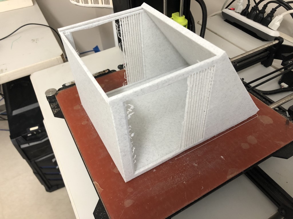
Once I finished printing the enclosure, I realized that some of the vents were too thin to print on our 3D printer, which was a little disappointing. I decided to keep the print (which took 14 hours!) and design new side panels to fit in the wall. I ripped out the exisitng vents and sanded the box a little bit.
// Insert photos of printing and completed product
Indoor Enclosure
I decided to use a laser-cut plywood enclosure for my indoor unit. First, I took some measurements of the display board with the LCD attached and then began designing in Fusion.
Above, a screenlapse of the design process in Fusion.
Above, you can see me laser cutting a test of the dimensions on cardboard.
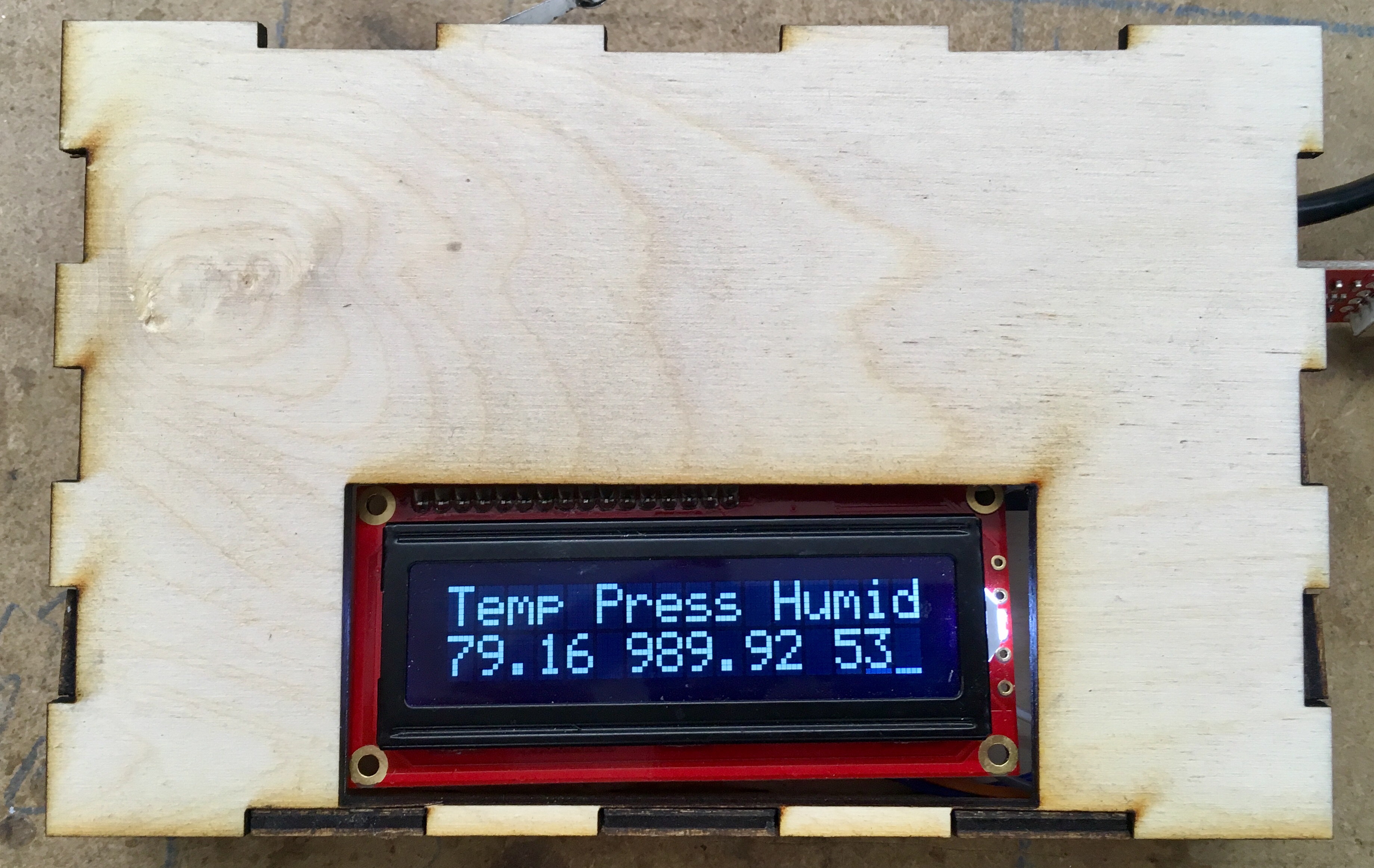
Above, a photo of the display board inside the completed plywood enclosure.
Project Files
Final Project Files (.brd, .sch, .xlsx (BOM), .f3d, .ino, .c files in .zip folder)