9. Input devices
For the individual project this week, I had to measure something, by adding a sensor to a microcontroller board that I have designed, and read it. As for the group project, we had to probe an input device’s analog levels and digital signals.
Individual Project
In order to prepare for my final project, I wanted to use some sort of a capacitive touch sensor for a microcontroller board. I didn’t want to directly jump into sensors with multiple inputs just yet before I try to understand how one loading sensor works on its own– that’s what I tried to do this week. I decided to choose the loading sensor even though it requires more stable grounding to the ground (from the person) since it only required one connection to a touch pad. Because of the coronavirus situation, I wanted to start off by understanding how the circuit and code worked before moving on to more complex sensors.
I first looked at Neil’s example of the loading board and the components he used in his schematic. I wanted to add an LED, though, to be able to see when and if a data signal was coming through.
Eagle
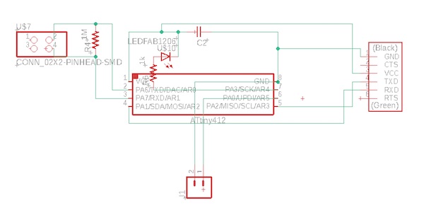
I first opened up Eagle and made a new project called inputDevices. I looked at Neil’s board as a reference, but I wanted to use an ATtiny412 instead of the ATtiny45. I switched out the 3x2 pins and instead used UPDI. For this I referenced the board from week 6. I realized I also did not need the resistor on the reset pin, since there isn’t a reset pin necessary for using a jtag2updi programmer. I found on the datasheet for the ATtiny412 that pin 6 also acts as a reset pin, but I didn’t need to use it. I also added the LED and its resistor on the open pin (PA0) to read data coming in. Using the ATtiny412 is making much more sense now as concepts are starting to click. I’ve realized the role of using the UPDI pin, as well as Tx and Rx pins. While changing the schematic to match the ATtiny412 from the ATtiny45, I’ve realized that MISO and MOSI pins match with Tx and Rx pins, respectively.
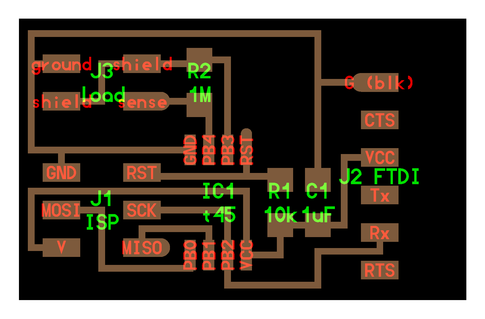
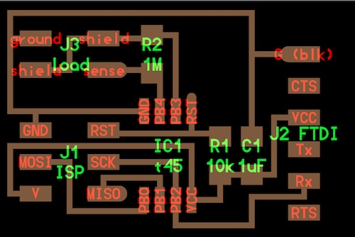
This is what the schematic looked like:
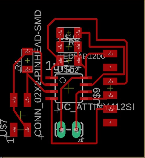
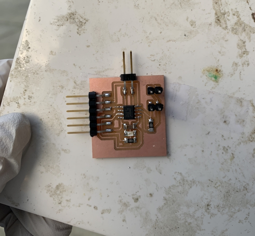
Then I opened up the BRD file and reorganized all the components. I tried to make the traces as symmetrical as possible, but it was still difficult to get the 2x2 pin and resistor satisfyingly neat.
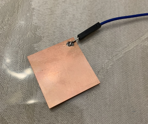
Then, I sent the board design to Mr. Rudolph, since he had to Othermill, and got the board milled. I requested two boards: one board with the traces, and one without. The board without would act as the actual copper sensor. After a day, I got both the boards and components necessary for soldering.
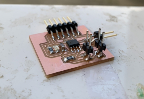
Soldering
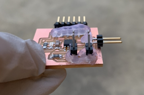
Honestly, soldering has become so much fun. I soldered all the parts on: 1x ATtiny412, 1x1uF capacitor, 1x1k Ohm resistor, 1x1M Ohm resistor, 1xRed LED, 6x1 flat pin header, 2x1 flat pin header, 2x 2x1 pin headers. I forgot to specify that I wanted L-shaped pin headers when I messaged Mr. Rudolph, so I got normal pin headers. I had to make do, so I stuck them in a thicker pile of solder. I also hot glued all the pins just in case– I didn’t want any ripped traces this week. (Note: my parents made me wear gloves, just in case any of the parts had the virus).
I also soldered a male-female jumper wire onto the board without traces. The solder looked cold, and at this point my soldering iron seemed like it didn’t heat the solder as quickly with the tip as before. I’m not sure what causes this, since it’s happened before, but I’m hypothesizing that I might be pushing the soldering iron into the sponge too hard to the extent that it’s going into the plastic– I have no idea though.
Wiring
Then it was time to wire things together. I used the jtag2updi programmer from last week, but this time, I didn’t need to use my ratchet resistor setup as I had a 4.9k Ohm through hole resistor on hand. This is what the wiring setup looked like:
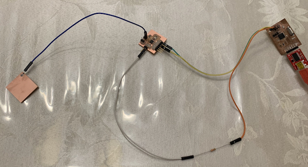
I assumed that the sensor only needed a pin to the pin labelled “sense” on Niel’s example board, since that’s where the voltage will get drawn out from.
Coding, Testing, and Reading
I first started off by looking at Niel’s example code. It didn’t make too much sense, so I decided to start off with the most basic concept Arduino code of what happens. Mr. Rudolph helped me write this code, and after looking at it, the concept of capacitive sensors make much more sense– we measure the voltage two times: first when we power the capacitor a little, second when we discharge it. The measurements of the pulled voltage vary based off of the capacitance.
#include <util/delay.h>

#define CHARGEPIN 0
#define READPIN 1
#define pause 200

int reading1, reading2;

void setup() {
  // put your setup code here, to run once:
  Serial.begin(115200);
  pinMode(CHARGEPIN, OUTPUT);
  digitalWrite(CHARGEPIN, LOW);
  pinMode(READPIN, INPUT);
}

void loop() {
  // put your main code here, to run repeatedly:
  delay(100);
  digitalWrite(CHARGEPIN, HIGH);
  _delay_us(pause);
  reading1 = analogRead(READPIN);

  digitalWrite(CHARGEPIN, LOW);
  _delay_us(pause);
  reading2 = analogRead(READPIN);

  Serial.println(reading1, reading2);
}
I tested this code, and at first it didn’t work. That’s because after I coded it, I directly went to the serial monitor when my boards were wired the way they look in the picture in the Wiring section. I learned that I had to get rid of the programmer after the board was programmed and directly connect the board to the ftdi chip. Then I opened the serial monitor, and this is what I got.
The outputs in the serial monitor did change after I touched the sensor. They changed from varying numbers and ¿ symbols to two character strings. However, this is not what I wanted for my board. I went back to the code. I looked at Niel’s code and found that aside from much of the serial monitor code and analog to digital conversions, the bulk of the code was what I had, except repeated three times with different delay times. I changed my code so that it did this:
#include <util/delay.h>

#define CHARGEPIN 0
#define READPIN 1
#define settleDelay 100
#define chargeDelay1 1
#define chargeDelay2 10
#define chargeDelay3 100

int reading1, reading2;

void setup() {
  // put your setup code here, to run once:
  Serial.begin(115200);
  pinMode(CHARGEPIN, OUTPUT);
  digitalWrite(CHARGEPIN, LOW);
  pinMode(READPIN, INPUT);
}

void loop() {
  //send framing
  Serial.print(1);
  Serial.print(2);
  Serial.print(3);
  Serial.print(4);

  //settle, charge, and wait
  delay(settleDelay);
  digitalWrite(CHARGEPIN, HIGH);
  _delay_us(chargeDelay1);
  reading1 = analogRead(READPIN);
  //settle, discharge, and wait
  delay(settleDelay);
  digitalWrite(CHARGEPIN, LOW);
  _delay_us(chargeDelay1);
  reading2 = analogRead(READPIN);
  //send result
  Serial.println(reading1, reading2);

  //settle, charge, and wait 2
  delay(settleDelay);
  digitalWrite(CHARGEPIN, LOW);
  _delay_us(chargeDelay2);
  reading1 = analogRead(READPIN);
  //settle, discharge, and wait 2
  delay(settleDelay);
  digitalWrite(CHARGEPIN, LOW);
  _delay_us(chargeDelay2);
  reading2 = analogRead(READPIN);
  //send result
  Serial.println(reading1, reading2);

  //settle, charge, and wait 3
  delay(settleDelay);
  digitalWrite(CHARGEPIN, LOW);
  _delay_us(chargeDelay3);
  reading1 = analogRead(READPIN);
  //settle, discharge, and wait 3
  delay(settleDelay);
  digitalWrite(CHARGEPIN, LOW);
  _delay_us(chargeDelay3);
  reading2 = analogRead(READPIN);
  //send result
  Serial.println(reading1, reading2);
}
Framing the output made it a lot easier to see when the sensor was being touched and when it wasn’t. When it wasn’t, the outputs between the frames were either empty, or had a 0 in it. When I touched the sensor, numbers larger than 1 usually appeared.
However, it still lagged and bugged out a lot, so I looked closer at the outputs. I realized that when I touched the board, the first number after the frame “1234” was usually a 1, and when I didn’t, it was usually a 6. I tried to utilize this to make a clearer output. I edited the code and commented out the 2 repetitions of the readings after the first one. This is the code I used, without the 2 repetitions after the first measurement included:
#include <util/delay.h>

#define CHARGEPIN 0
#define READPIN 1
#define settleDelay 100
#define chargeDelay1 1
#define chargeDelay2 10
#define chargeDelay3 100

int reading1, reading2;

void setup() {
  // put your setup code here, to run once:
  Serial.begin(115200);
  pinMode(CHARGEPIN, OUTPUT);
  digitalWrite(CHARGEPIN, LOW);
  pinMode(READPIN, INPUT);
  pinMode(4, OUTPUT); //LED pin
}

void loop() {
  //send framing
  /*Serial.print(1);
  Serial.print(2);
  Serial.print(3);
  Serial.print(4);*/

  //settle, charge, and wait
  delay(settleDelay);
  digitalWrite(CHARGEPIN, HIGH);
  delay(chargeDelay1);
  reading1 = analogRead(READPIN);
  //settle, discharge, and wait
  delay(settleDelay);
  digitalWrite(CHARGEPIN, LOW);
  delay(chargeDelay1);
  reading2 = analogRead(READPIN);
  //send result
  Serial.println(reading1, reading2);
}
This one seemed to work a lot better. 1’s and 6’s were printed, but I realized that a weird character was printed after each 1 or 6. To fix this, I decided to only print out reading1 instead of both reading1 and reading2. I also tried to get my LED working, so I added an if statement to try to get it working. This is the code I used:
#include <util/delay.h>

#define CHARGEPIN 0
#define READPIN 1
#define settleDelay 100
#define chargeDelay1 1
#define chargeDelay2 10
#define chargeDelay3 100

int reading1, reading2;

void setup() {
  // put your setup code here, to run once:
  Serial.begin(115200);
  pinMode(CHARGEPIN, OUTPUT);
  digitalWrite(CHARGEPIN, LOW);
  pinMode(READPIN, INPUT);
  pinMode(4, OUTPUT); //LED pin
}

void loop() {
  //send framing
  /*Serial.print(1);
  Serial.print(2);
  Serial.print(3);
  Serial.print(4);*/

  //settle, charge, and wait
  delay(settleDelay);
  digitalWrite(CHARGEPIN, HIGH);
  delay(chargeDelay1);
  reading1 = analogRead(READPIN);
  //settle, discharge, and wait
  delay(settleDelay);
  digitalWrite(CHARGEPIN, LOW);
  delay(chargeDelay1);
  reading2 = analogRead(READPIN);
  //send result
  Serial.println(reading1);
  if (reading1 < 5){
    digitalWrite(4, HIGH);
    delay(100);
  }
}
To my surprise, the outputs changed to numbers in the 1000 range, but everything worked a lot more cleanly. When I didn’t touch the board the reading was usually 1023, and when I touched the sensor the reading was 980-1010. However, the LED didn’t work and instead stayed lit the entire time. Even after I changed the if statement to if (reading1 < 1020){, the LED still did not work. Given the time constraint right now, however, I will take the serial monitor outputs as a small success.
Note: I realize that my outputs in the serial monitor came out at an oddly slow pace. I’m not sure what caused this to happen, but if I find out I will add to this page.
These are the files I used for this week:
Update: As I was working on the Interfaces week (week 12), I found that after I deleted the unnecessary code, the serial monitor outputs updated more quickly. This is the most efficient code I could get as of now:
#include <util/delay.h>

#define CHARGEPIN 0
#define READPIN 1
#define settleDelay 100
#define chargeDelay 1

int reading;

void setup() {
  // put your setup code here, to run once:
  Serial.begin(115200);
  pinMode(CHARGEPIN, OUTPUT);
  digitalWrite(CHARGEPIN, LOW);
  pinMode(READPIN, INPUT);
  pinMode(4, OUTPUT); //LED pin
}

void loop() {
  //settle, charge, and wait
  delay(settleDelay);
  digitalWrite(CHARGEPIN, HIGH);
  delay(chargeDelay);
  reading = analogRead(READPIN);
  //send result
  Serial.println(reading);
  if (reading < 1015){
    digitalWrite(4, HIGH);
    delay(100);
  }
}
Group Project
The group project is linked here. Funny story: I had a small DSO138 oscilloscope that I brought home with me, but after I mistakenly plugged in a wrong power source, one of the capacitor exploded. I found out that some capacitors have paper/fur looking insides.