3. Computer Controlled Cutting
This week I worked on making a vinyl cut sticker and a parametric press-fit construction kit for my individual projects, as well as characterizing our lasercutter’s focus, power, speed, rate, kerf, and joint clearance for our group project.
Vinyl Cut Sticker
I wanted to make a boba sticker, since I’ve been craving it for awhile. I Google searched “boba sticker png” and found a design of boba that I liked. I then copy and pasted into CorelDRAW.

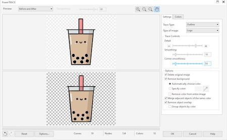
I Bitmap detail-traced the image (with a smoothing and corning smoothness of 10).
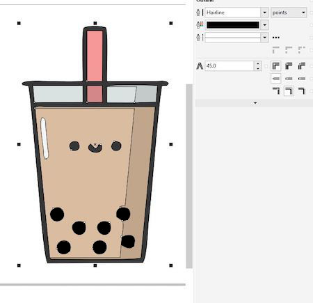
I selected the entire Bitmap and changed under its Object Properties menu, I changed its line thickness to “Hairline.”
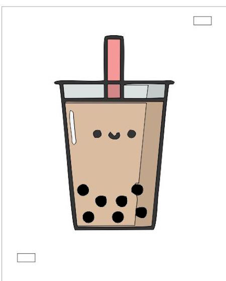
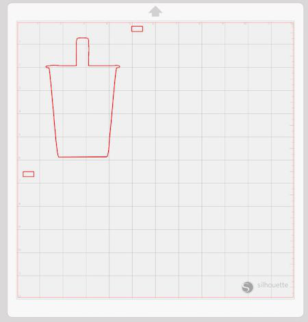
I wanted to try out using registration squares in this sticker. Before when I had used the vinyl cutter I had freehanded most of my more complex stickers, and I had heard about how useful registration cuts were. So, I added small rectangles on two corners of the sticker design.
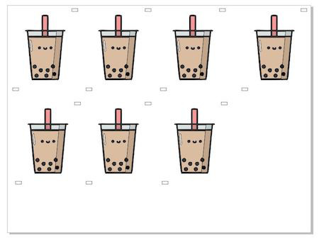
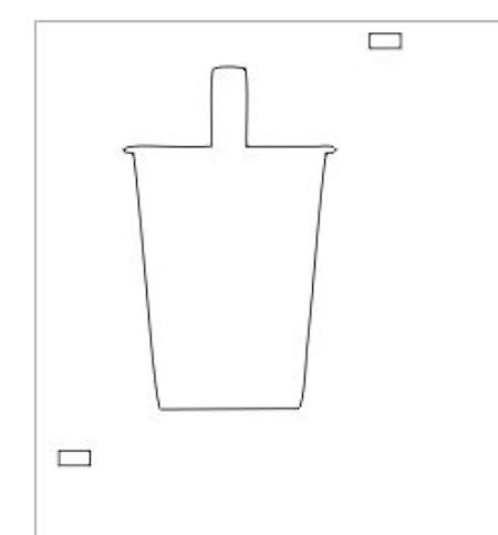
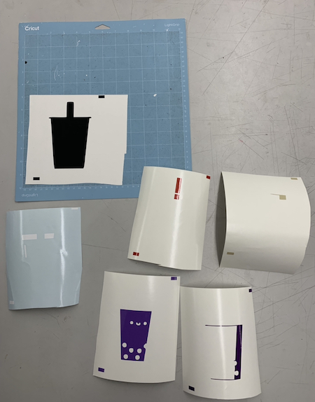
Since this sticker requires multiple layers, I copy and pasted the Bitmap six times, once for each part of the sticker. I split up each layer based on the color of the vinyl I would use for it. Then on each copy of the design, I deleted what I didn’t need, and I changed the entire design to “No Fill” under the Object Properties menu.
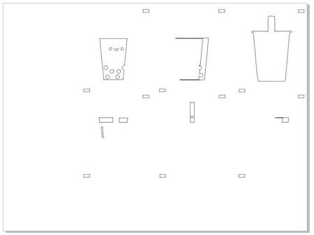
It was time to move towards the vinyl cutter. For each version of the design, I made a new file so that I could easily export it into Silhouette, the program I would be using to make my sticker. One of the separated files looked like this:
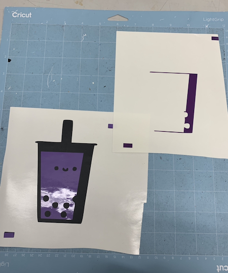
After I had a file for each layer, I chose the colors I wanted to use. I went for a purple drink instead of a tan one to show a taro milk tea instead of a more traditional milk tea. Everything else stayed similar to the original design.
After I had the colors I wanted, I exported each file as an SVG and imported them into Silhouette one at a time.
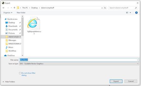
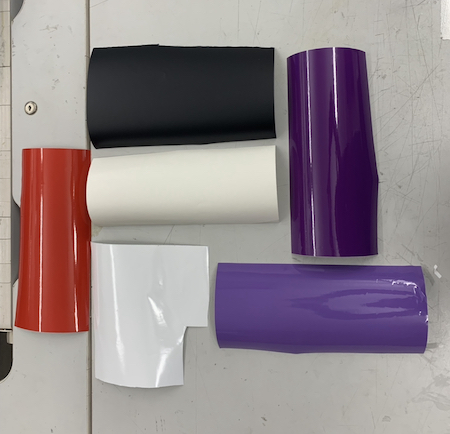
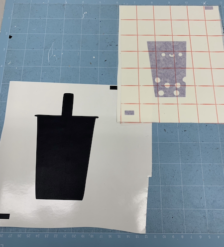
I then set each color of vinyl up on the grid one at a time. I first started with black, since that would be the base of my sticker then went through the rest of the colors. The following pictures show the setup process with the light purple vinyl. I aligned the blue grid cut mat with the line provided in the vinyl cutter, and then I loaded it in.
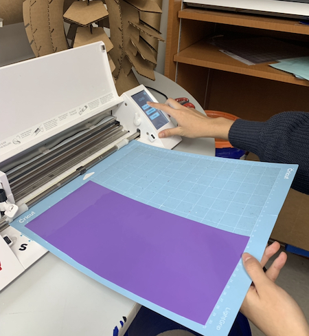
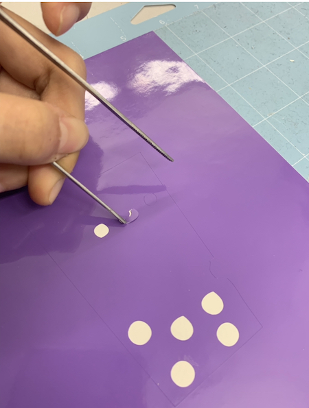
I made sure that my cut settings were on the material for “Vinyl, Glossy” and that the blade was on the first setting. After I got each cut done, I unloaded the cut map. I first set the black cut on the blue cut mat so that I had a relatively firm place to work on. I used tweezers to pick off any of the parts of the vinyl that weren’t needed. The rest of the cuts were nearby.
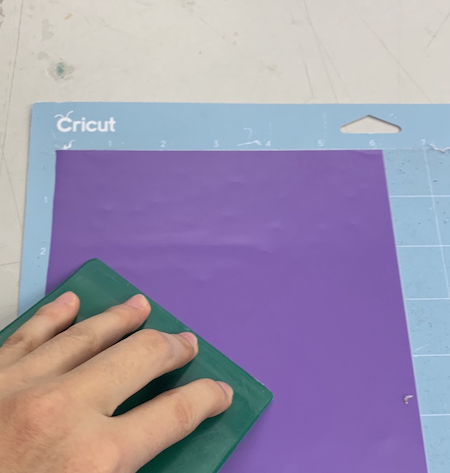
I used transfer tape for the light purple cut and tried to stick it onto the black layer and align the registration marks.
However, I realized that putting the marks on opposite sides of the design was inconvenient, since it made it harder to see whether I was putting the next layer on properly. After I first placed one light purple layer registration rectangle on the black one, I made a mistake and tried to peel up the sticker. I accidentally peeled up the rectangle with it. I lost track of where the rectangles were, and I decided to just freehand it, and it worked, although not perfectly. The rest of the layers weren’t centered, but I took it as an organic mistake.
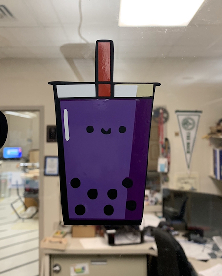
Next, I stuck the rest of the layers freehandedly onto the base black sticker. I pressed transfer tape onto the sticker and peeled the vinyl backing off, and I placed the sticker onto the lab office window where the rest of the stickers were. I pressed down hard, and although I couldn’t squeeze out a few air bubbles, the boba was complete! This is what my final sticker looked like.
Parametric Press-fit Construction Kit
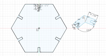
This week, I also worked on a parametric press-fit construction kit. I explored some kits that previous year Fab Academy students had made before and got an understanding of how such kits work. Then I started designing my own. I used Fusion360, since I’ve used a little bit of parametric design on there from the last week. I first started off sketching a hexagon using the Circumscribed Polygon option under the create dropdown of the sketch workspace. I also made a side connector joint. I made a parameter for the width of the connector joint and called it connector width.
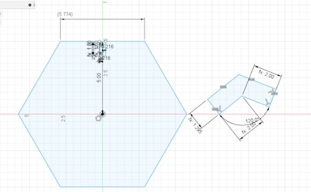
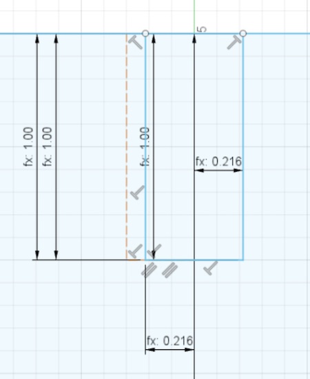
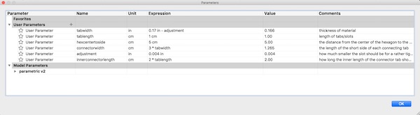
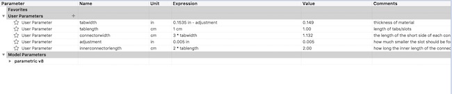
I then made each tab using parameters. Parameters are helpful because they allow the user to change multiple things in a design that correspond with each other just by changing one value. I decided to make the tab length 1 cm. As for the tab width, I had to take into account the laser cutter kerf. I made an adjustment parameter of 0.004 based on the kerf found in the group project (I made it slightly smaller than the found kerf because I didn’t want too tight of a fit). The tab width was the value of the adjustment subtracted from the material thickness, or 0.17in - adjustment.
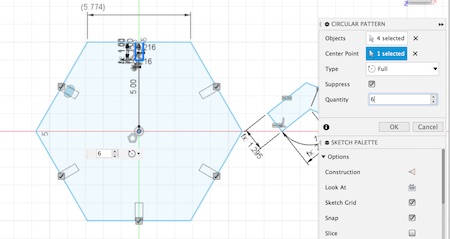
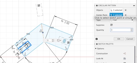
I used the Circular Pattern option under the create dropdown to repeat the tab on all six sides of the hexagon. I did the same for the connecting joint. I also gave the width of the connector joint a value of 3 times the tabwidth, since I wanted some excess connector to stick up off of surface of the hexagon. I made the length of the smaller side of the connector joint 2 times the tablength to make enough space for the hexagons to come together after construction.
Afterwards, I realized I forgot to fillet the entrances of the tabs in the sketch. A student from the previous year’s Fab Academy class told me that it would be smart to fillet the edges to make it easier for construction. I went back to the sketch and filleted the corners. This also made the joints similar to chamfer joints, except the fillets are curved.
These were my parameters for the design:
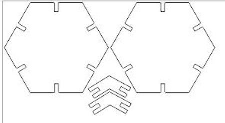
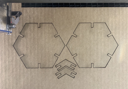
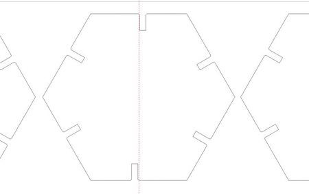
Next, I had to move the file to CorelDRAW so that I could cut it on the laser cutter. I exported my sketch as a DXF file and opened it up on Corel. I copied the design and pasted it again so that I had two sets of the design when cut to test out the joint fittings.
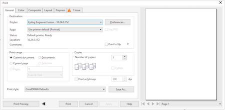
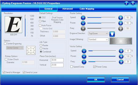
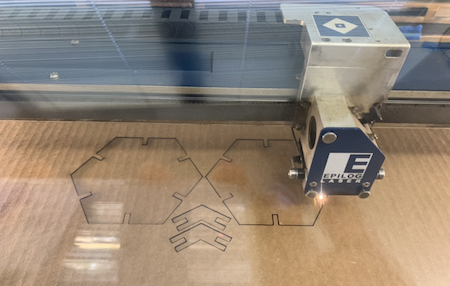
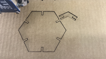
After opening the file in Corel, I cut the design. I opened up the print menu by clicking Ctrl+P, and then I adjusted the print settings (15 speed, 100 power, 25 frequency). Then I hit Go and let the laser cutter do the rest.
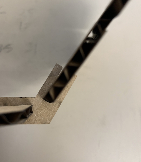
I tried to assemble the pieces I had and quickly realized that the connections and joint fits were too loose.
I went back to Fusion and changed my parameters so that the pieces would fit together better.
I cut the design again with the same print settings, this time with only one design to see if the fit would be tighter.
This cut fit together well, but when I went back to copy and paste the design multiple times, I realized that the hexagon was no longer symmetrical after I changed the parameters. I hadn’t constrained the sketch well enough.
I then went back to Fusion again to edit the sketch so that it was symmetrical. I added a construction across the middle of the hexagon and contrained it horizontally. I also added a construction line from the center of the hexagon to the middle of a tab and constrained it to be perpendicular to the first construction line. I also made the fillets of the sketch larger, changed the radius from 0.1 cm to 0.2. Now the sketch was correct and ready to cut.
After I cut the design, I realized a 3D shape with only hexagonal faces did not exist. After trying to make a shape, I realized I needed to design a square for every “corner” of the truncated shape. I added to the design a square of side length (10/3)(sqrt(3)) and added tabs on the four sides.
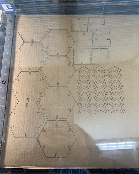
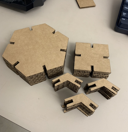
Then I cut the design on the laser cutter with the same settings as before. I only cut out one hexagon, square, and joint piece because I wanted to test out the square. I found that the square fit well.
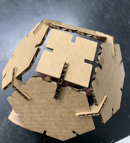
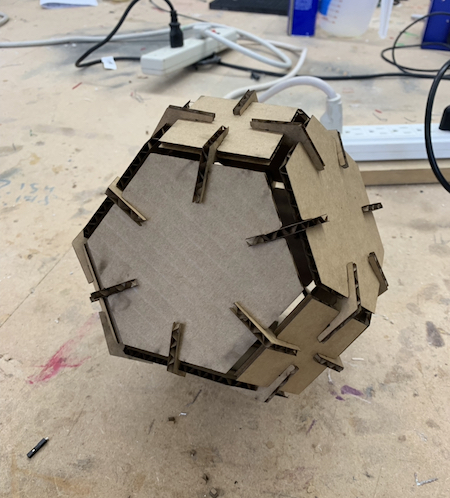
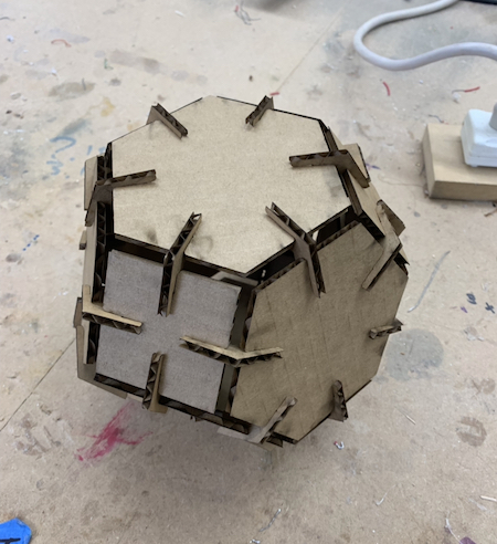
Then I cut out 8 hexagons, 6 squares, and 36 joint pieces. I pieced the construction kit together and got a solid tetradecahedron.
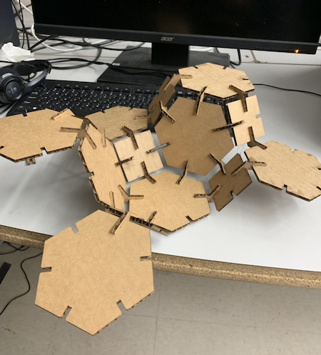
I wanted to test out rearranging the kit in different ways. I realized I would need to cut more of the design parts to fully make more sets of arrangements, but I came to make this arrangement with the parts I had.
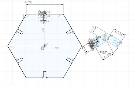
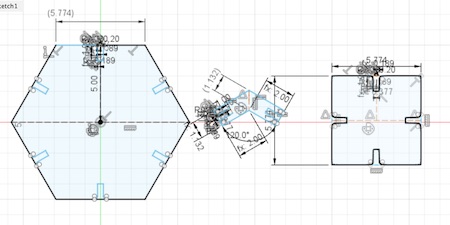
This is the Fusion sketch I made. I extruded it by the width of the cardboard material to show what it looks like:
Here are all the final files for this week. Week 3 Files
Group Project
For this group project, we were tasked with characterizing our lasercutter’s focus, power, speed, rate, kerf, and joint clearance.
For this project, I specifically found the definitions of all the key words and concepts we needed to understand, like kerf and joint clearance, and explained them to our group. These concepts were particularly confusing to our group, and after we spent around an hour trying to understand everything, it clicked. I helped a lot on documenting our progress as everyone went along, making sure everyone communicated with each other. I also helped design the second laser cut settings file with 27 combinations, measure the kerf of the 2 inch square, and set and engraved the logos for the laser focus section.
Here is the link for the full group project documentation.
Before this project, I had known vaguely what a laser cutter’s focus, power, and speed were. However, from this group project, I learned more specifically what power, rate, kerf, and joint clearance were, and how different settings affect a laser cut. I now know more about how the kerf of a laser cutter is the cut size of the laser, and how joint clearance can be affected depending on the kerf. Everything explored about the relationships between different settings and cuts in the group project was something that I hadn’t explored in depth before.