15. Molding and Casting
The group assignment this week was to review the safety data sheets for each of your molding and casting materials, then make and compare test casts with each of them.
The individual assignment was to design a mold around the stock and tooling that you’ll be using, mill it (rough cut + (at least) three-axis finish cut), and use it to cast parts
Group Assignment
This is the link for the group assignment.
Individual Assignment
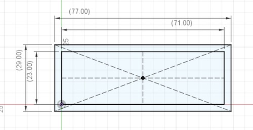
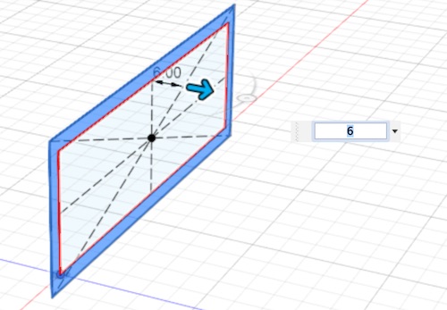
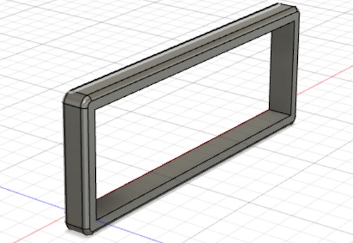
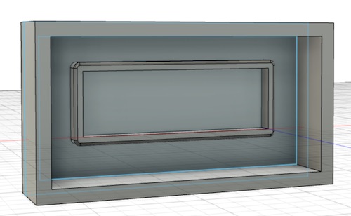
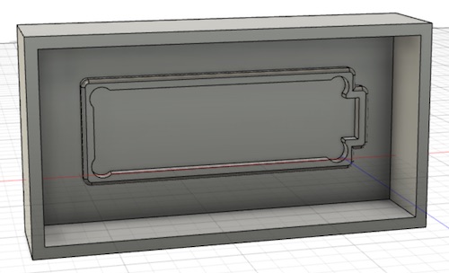
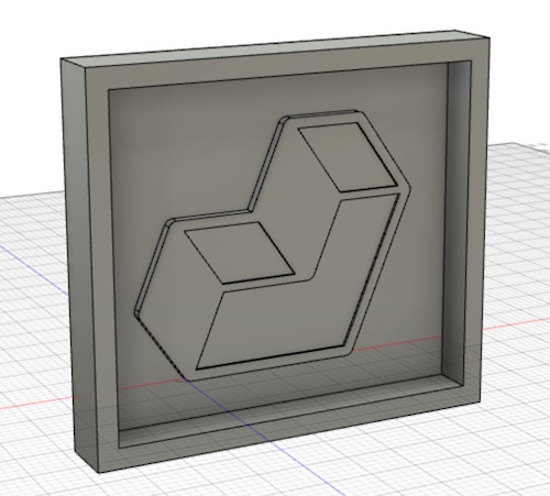
This week, I wanted to make something that I would likely use in my final project, so I decided to mold and cast a frame for my LCD display. I first started in Fusion and created a new file. I started by making sketch, making two concentric rectangles as per the size of the display, and extruding the middle by 6 mm. I added dogbones to account for the mill size. Then I made a rectangular sketch surrounding the frame, and extruded the back of it by 6 mm and the edges by 20 mm. Afterwards, I realized I missed a part of the display that juts out of the rectangle, so I adjusted the design as shown in the last picture of the following series:
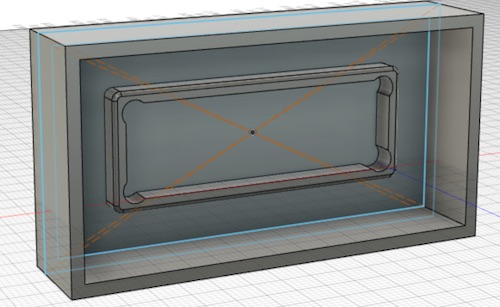
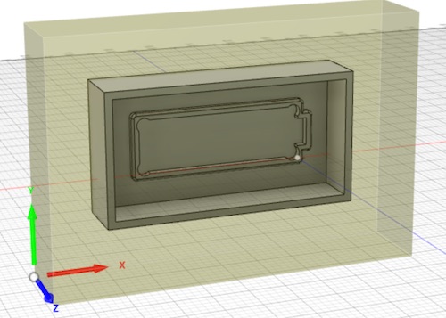
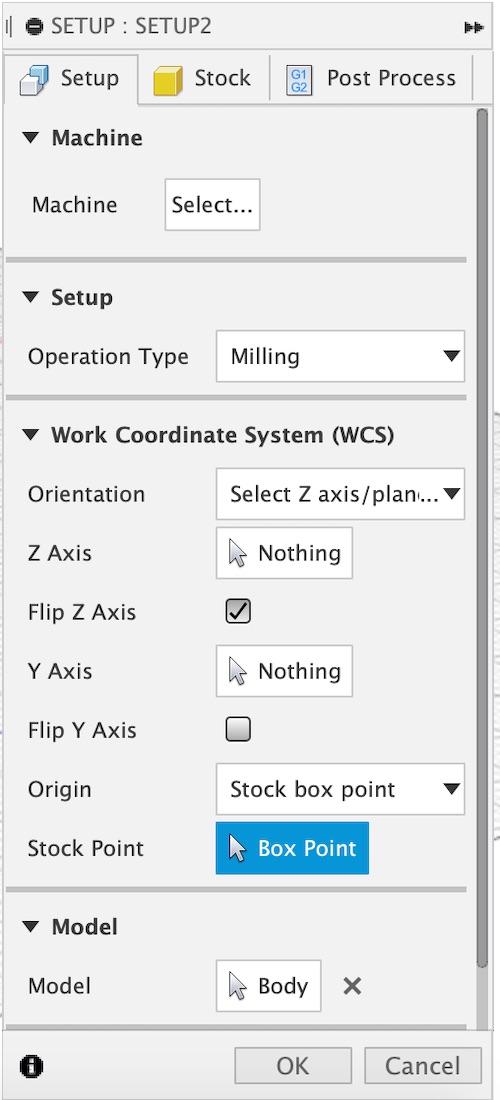
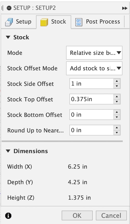
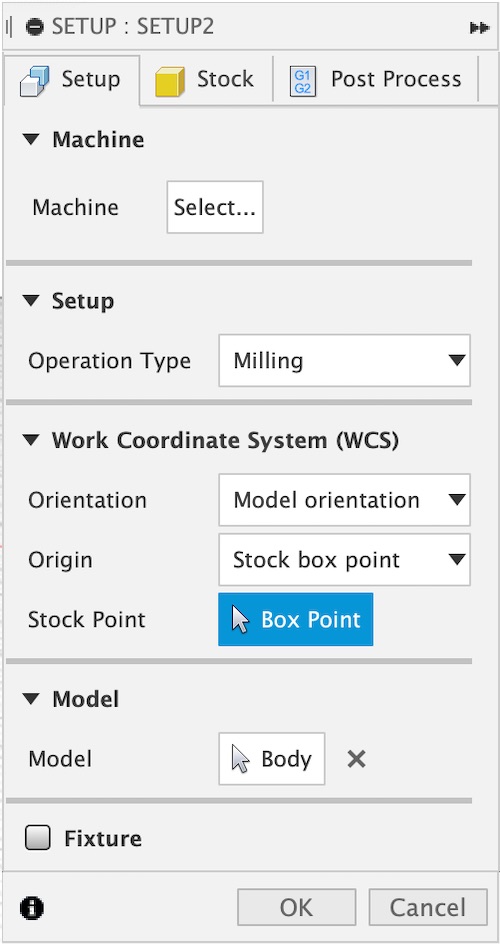
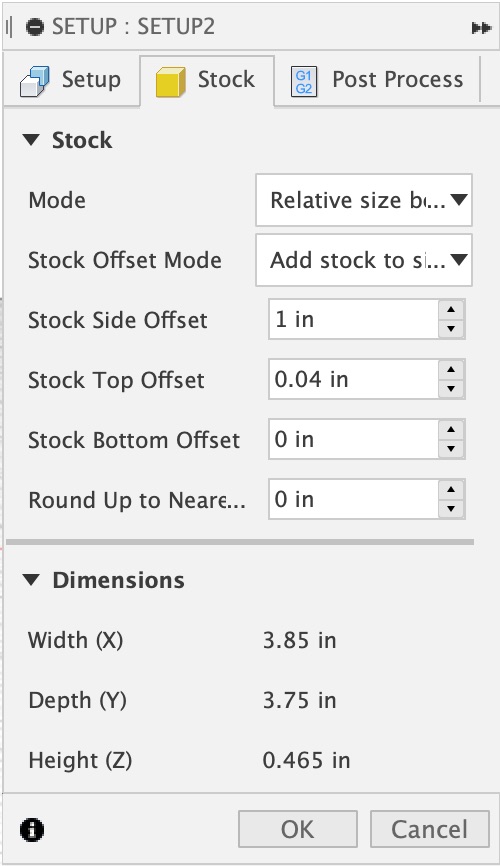
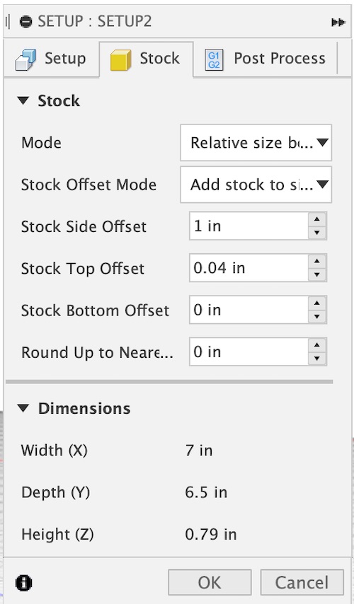
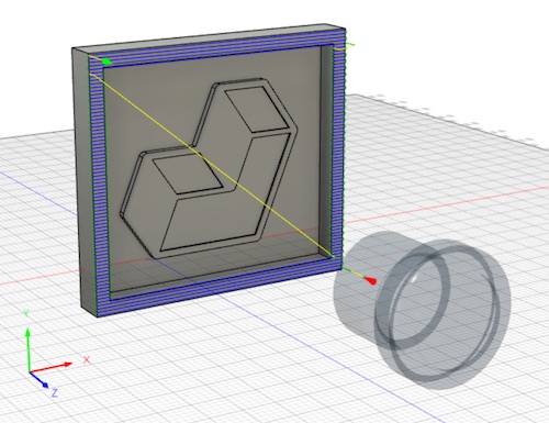
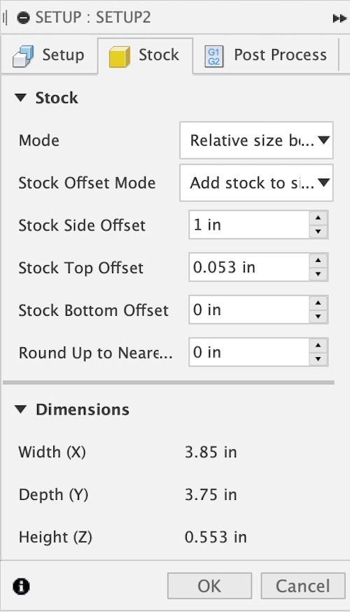
After I made the design, I went to the Manufacture side of Fusion. I first had to make a setup. I first adjusted the stock dimensions under the Stock tab. For the height and width, I ofset each dimension by 1 inch. After, I needed to adjust my height as well. To get my height to the correct dimension, I needed to add a top offset, but I couldn’t since I didn’t have my foam block yet. I also had to flip the z axis, as it was in the opposite direction in the beginning. After setting up the dimensions of my stock, I moved the setup origin to the bottom back left corner so that the xyz axes would correlate with those of the Shopbot. The settings for the stock dimensions and origin location are shown below:
Changing Directions
After meeting with Dr. Fagan and Dr. Taylor, I decided to switch molding and casting projects. I realized that the mold I had planned to make would have been relatively useless, as there was no way to attach it to the wood nor the lcd display. So, I decided that I wanted to make something for fun– a small logo for Aid First.

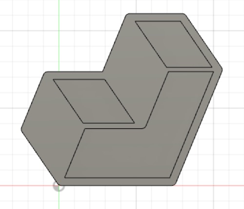
I went through the same process as before, except for the logo. It took awhile to measure out angles and dimensions, as many of the measurements were small (I wanted to be able to mill it on the Othermill). Afterwards, it looked like this!
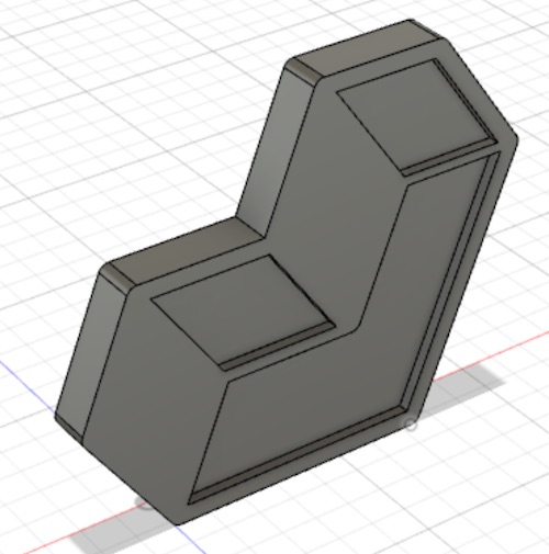
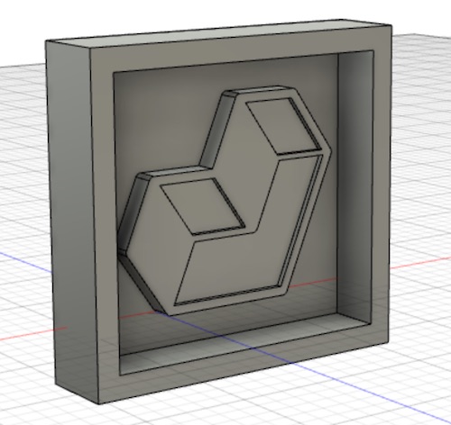
Then I added the box frame:
I made a new setup to set up the dimensions of my stock. I couldn’t be sure of what the top offset dimension was, since I didn’t have my foam block.
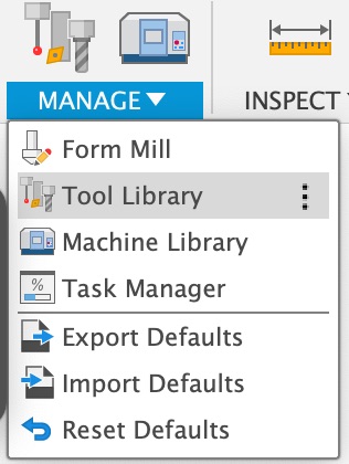
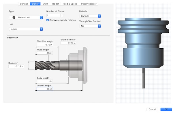
Then it was time to make the toolpath. I started by making a new tool. I followed Mr. Rudolph’s workflow tutorial (the link is restricted, as it is a Google slides that is shared with students. It is very in depth though.) I went to the Manage section and went to Tool Library.
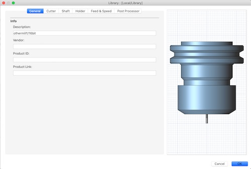
Then I went to my Local Library and added a new bit.
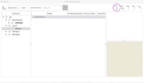
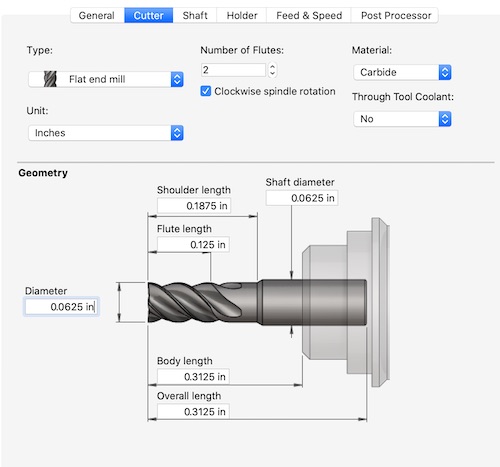
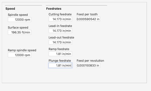
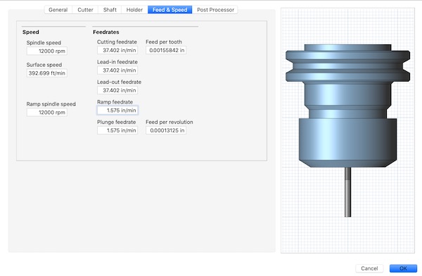
I added a little description to let me know that it was the Othermill 1/16” bit. Then I went through the top tabs, editing the Cutter and Feed & Speed tabs. In cutter, I changed the number of flutes to 2, the material to Carbide, and the Diameter to 0.0625. I left everything else as was, since I couldn’t measure the rest of the bit because of corona. In Feed & Speed, I referenced this document from week 4 to find the details about the mill. I used the 1/16” mill for FR1 in the Basic section, although this will be changed when I get my foam block. I changed the spindle speed to 12000 RPM, Cutting Feedrate to 14.173 in/min, and the plunge feedrate to 1.81 in/min.
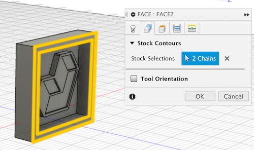
For the toolpaths, I started with a 2D Face toolpath, in case my foam block will be taller than what I need. In the Geometry tab, I set the Stock Contours to the two square outlines.
After I met with Dr. Fagan and Dr. Taylor for our weekly evaluations, I was told that I made my mold too small. So, I made a new version of the log that was around two inches. I repeated the Manufacturing process for the new design.
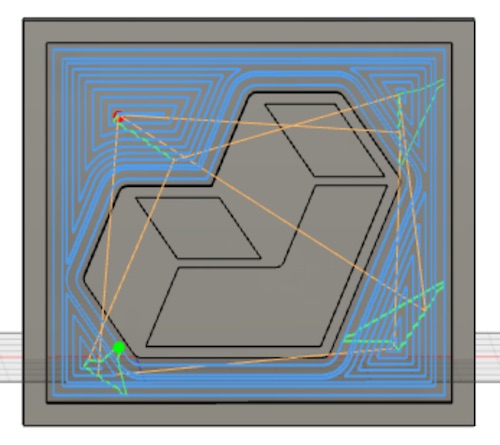
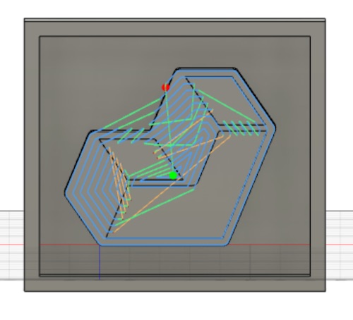
I then decided to change the bit to a 1/8” bit, since I wanted to make the milling process faster. I first made a 2D face toolpath, then three other 2D pocket toolpaths, clearing out the back side, the top part of the logo, and the inner pockets.
Here were my toolpaths. I selected the 1/8” bit for the tool, selected any chains I needed, and allowed for multiple passes under the Passes section. I also changed the ramp type to plunge under the Linking section. I followed the same instructions as I did in week 7 for the CNC week
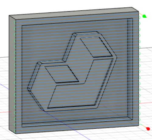
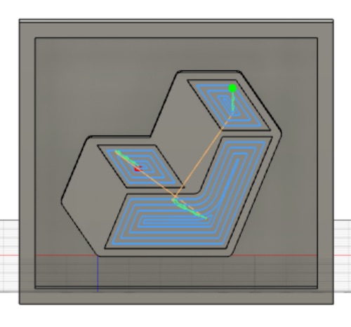
I then selected all the toolpaths and right clicked > simulate. This is what it looked like:
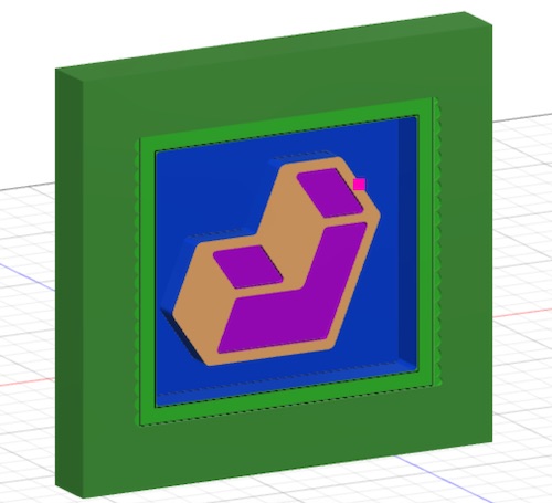
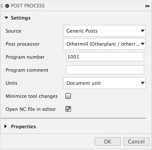
Before I milled out my logo charm, I found a block of engraving wax. I realized that I wouldn’t be able to mill out my larger design for the Aid First logo. So, I went back to the older design and redid all the toolpaths as shown above. After I got all the toolpaths, I exported it into Drive by clicking Actions > Post Process > Post Processor: Othermill (Otherplan).
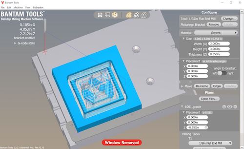
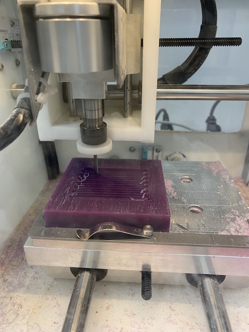
Then I went into Bantam, I changed the material to generic, set the size to match that of my setup, moved my toolpaths so that they would engrave the wax, and changed the bit to a 1/8” bit. Then I stuck two strips of Nitto tape onto the block of wax, and stuck it onto the bed of the mill. After everything was good, I clicked start milling.
Negative and Mold
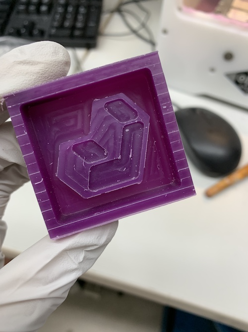
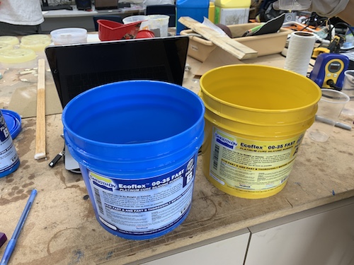
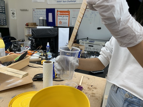
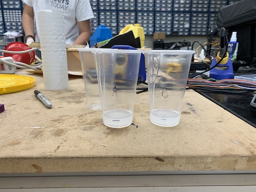
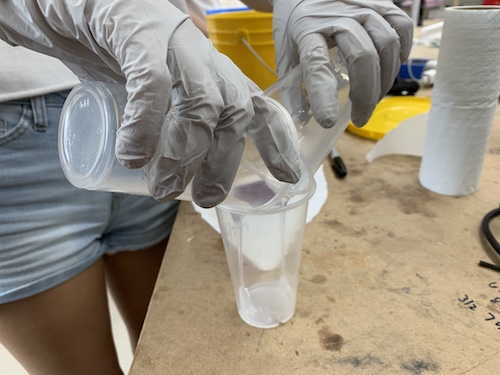
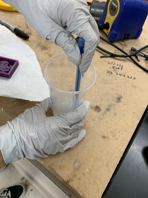
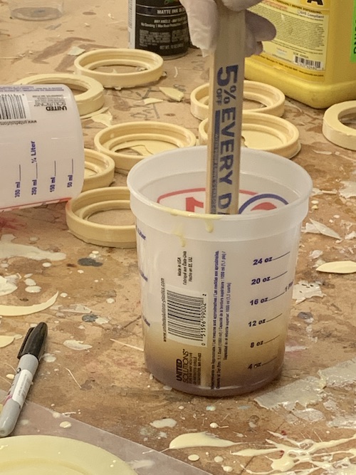
Since I wanted a charm, I wanted to make a soft mold. I used the ECOFLEX 00-35 FAST parts A and B to make the mold. After learning I had to use equal parts of both, I used a stick to pour equal parts of both parts into separate cups. Then I poured the contents of both cups into another cup labeled AB. I stirred the substances for around one minute, then slowly poured it into my milled wax piece.
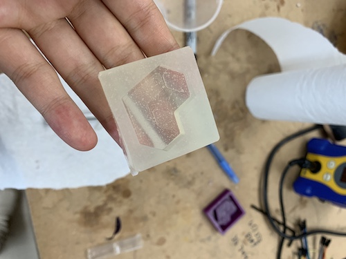
After I waited for around 5 minutes, I removed the mold from the wax and this is what I got!
Cast
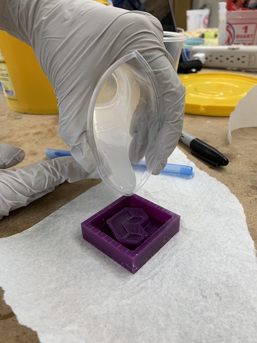
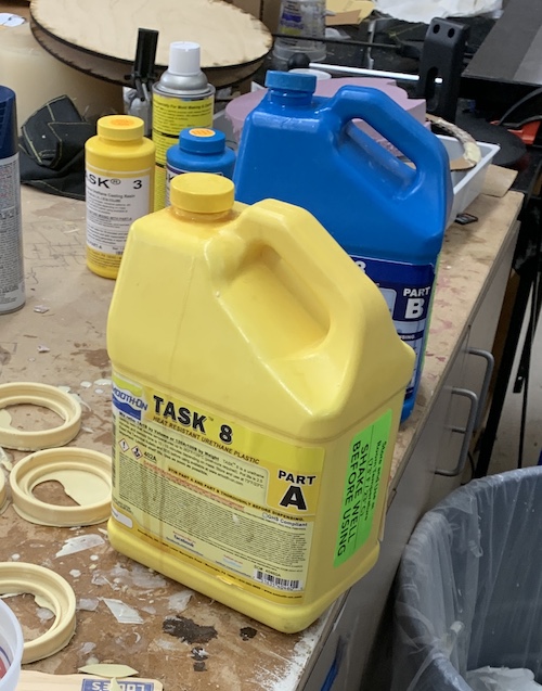
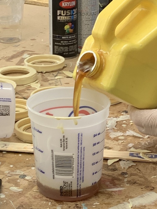
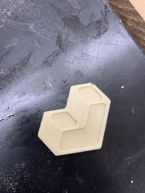
It was time to make the hard charm! For the casting, I used the Task 8 parts A and B. After reading the safety data sheet, I also had to use equal parts of both to make this charm. I learned that the mixture heats up very quickly, so I had to move quickly. Unlike using Ecoflex, I poured part A in the cup then part B on top. Since we had to use the mixture for some other molds too, we poured 12 oz of the combined parts A and B. Then I stirred for around 15 seconds and poured it into my mold.
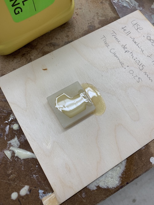
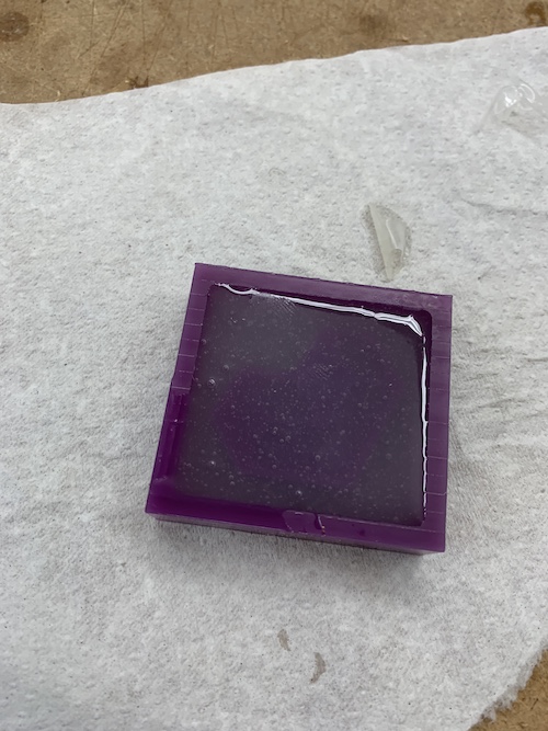
After waiting for 7 minutes, this is what I got! There was a little air bubble on the side, but other than that it was all good!
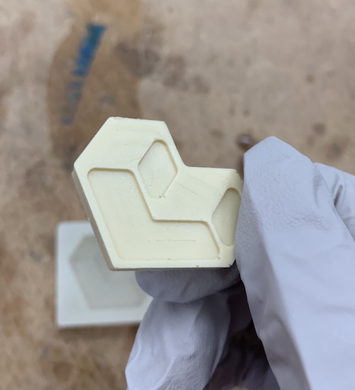
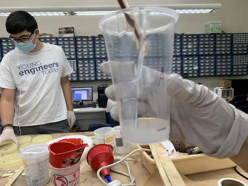
After searching online, I found that you can remove air bubbles by pouring in the cast from a high and narrow stream and by knocking the sides of the mold so that more air is released. If this doesn’t work, there is equipment like vacuum chambers and pumps that help remove bubbles. This week was really fun, and I enjoyed the molding and casting process a lot. I learned about needing hard vs soft molds and castings, as well as reading safety datasheets.
This was my gcode file and mold fusion file for this week: Week 15 files