Charlotte Latin 2020 Week 3 Group Assignment
Electronics Production
Characterizing the Milling Machine
For this group project, we were tasked with characterizing our lasercutter's focus, power, speed, rate, kerf, and joint clearance. The model of our laser cutter is: Fusion M2 32 / 40 Laser System (Model 13000 / 14000).
Plan
We first tried to figure out what each of these terms meant. After that, we came up with a plan to measure each of the things we needed to.
| Term | Meaning | |
|---|---|---|
| Focus | This is the diameter of the laser beam. Usually laser beams are 1/4 th inch in diameter, a series of mirrors and lenses makes it a lot smaller. | Source |
| Power | This is the output power or intensity of the laser. You can use values of 1-100 for power. | Source |
| Speed | This is how fast the laser is moving. Cutting at higher speeds results in less exposure while slower speeds means more exposure for the material. Engraving at slower speeds is better for more detail or smaller designs. Cutting and engraving speeds cannot be compared because cutting is slower than engraving. | Source |
| Rate | The cutting rate is the amount of time that the laser is able to touch the material within a given period. It can be limited by the laser's power, the material's thickness, whether or not the material is reactive or inert, and the material's properties. | Source |
| Kerf | The width of the laser beam that cuts into the material, how much is lost when cutting because the tool itself will remove some of the material. In the context of the laser cutter, the kerf is the width of the laser when it cuts the material. | Source |
| Joint clearance | In the context of using a laser cutter specifically, the joint clearance is the kerf, since the laser cutter provides us with the clearance. | Explained by Mr. Rudolph |
To begin, we planned to make a file on Corel Draw with lines to show the different power, speed, and frequency levels. To reveal the focus levels, we planned to make a separate document with a couple lines that were differently RGB colored and use color mapping. We would manually change the focus on the laser cutter for each cut. For kerf, we planned to laser cut a small square out of plywood and measure the square to find out how much material the laser cutter vaporized. This would also apply for the joint clearance because in this setting the joint clearance was the kerf. Each member of our group contributed to this project in different areas, though we mostly collaborated as a whole.
Determining Power, Speed, Frequency
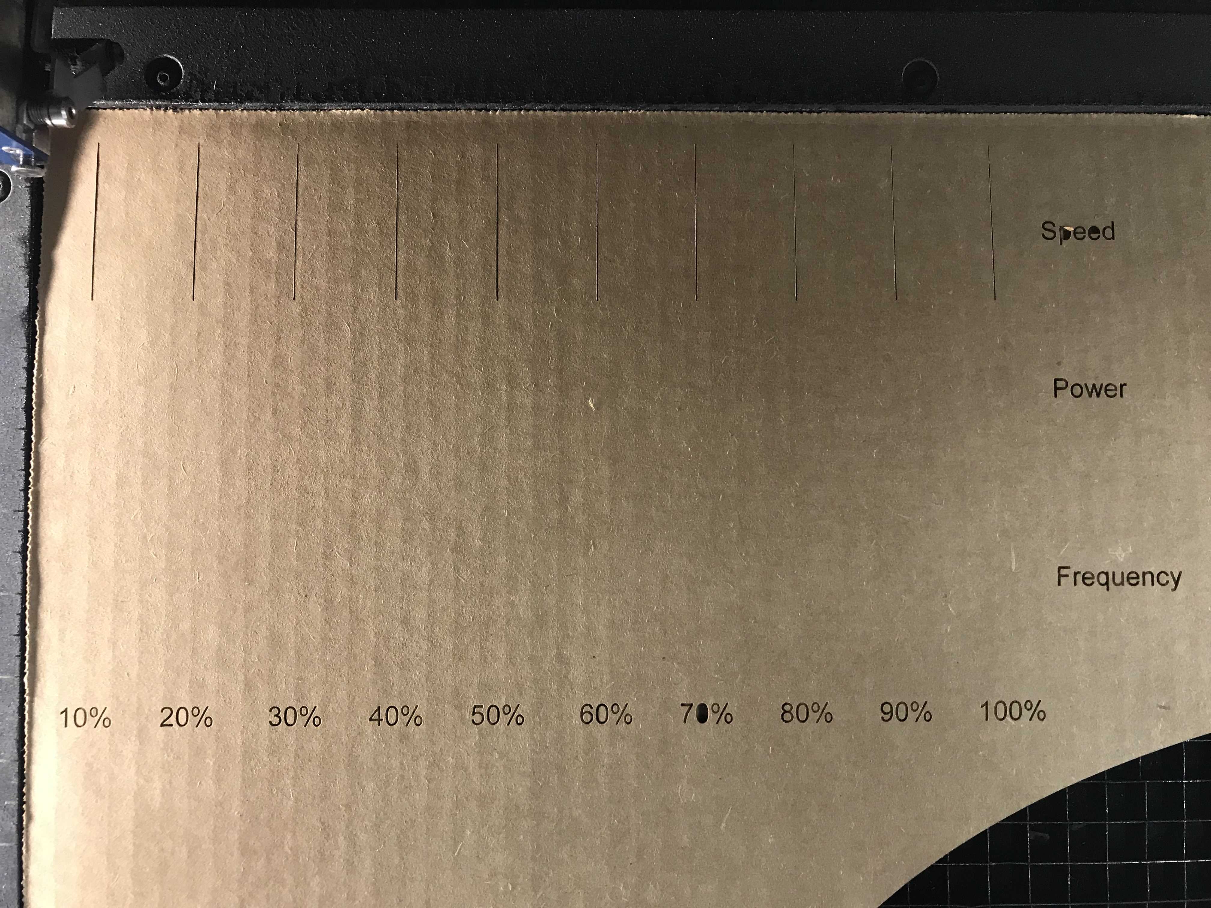
To measure power, speed, and frequency, we're going to cut a series of lines into a piece of cardboard for multiple different values in each of these categories. We labeled each of the lines so you can clearly see what changed in each line. When designing the file, we made sure the lines each had different RGB values so that we can utilize color mapping on the laser cutter and set different power, speed, and frequencies for each line. Red = Different categories: 100 = Speed, 50 = Power, 0 = Frequency Green = The percentage value, ie: 10 for 10% Blue = Always 0

The first error we ran into this week was when we decided to cut out the lines, changing one value of either speed power or focus by 10% increments. After cutting the design above, we realized that we were limited in testing the number of combinations of power, speed, and frequency. We wouldn't be able to see the variation of cuts because we changed the values of either speed, power, or focus by 10% increments. This method would result in us only finding values for 10 unique combinations, and would not give us a variety of possible combinations.
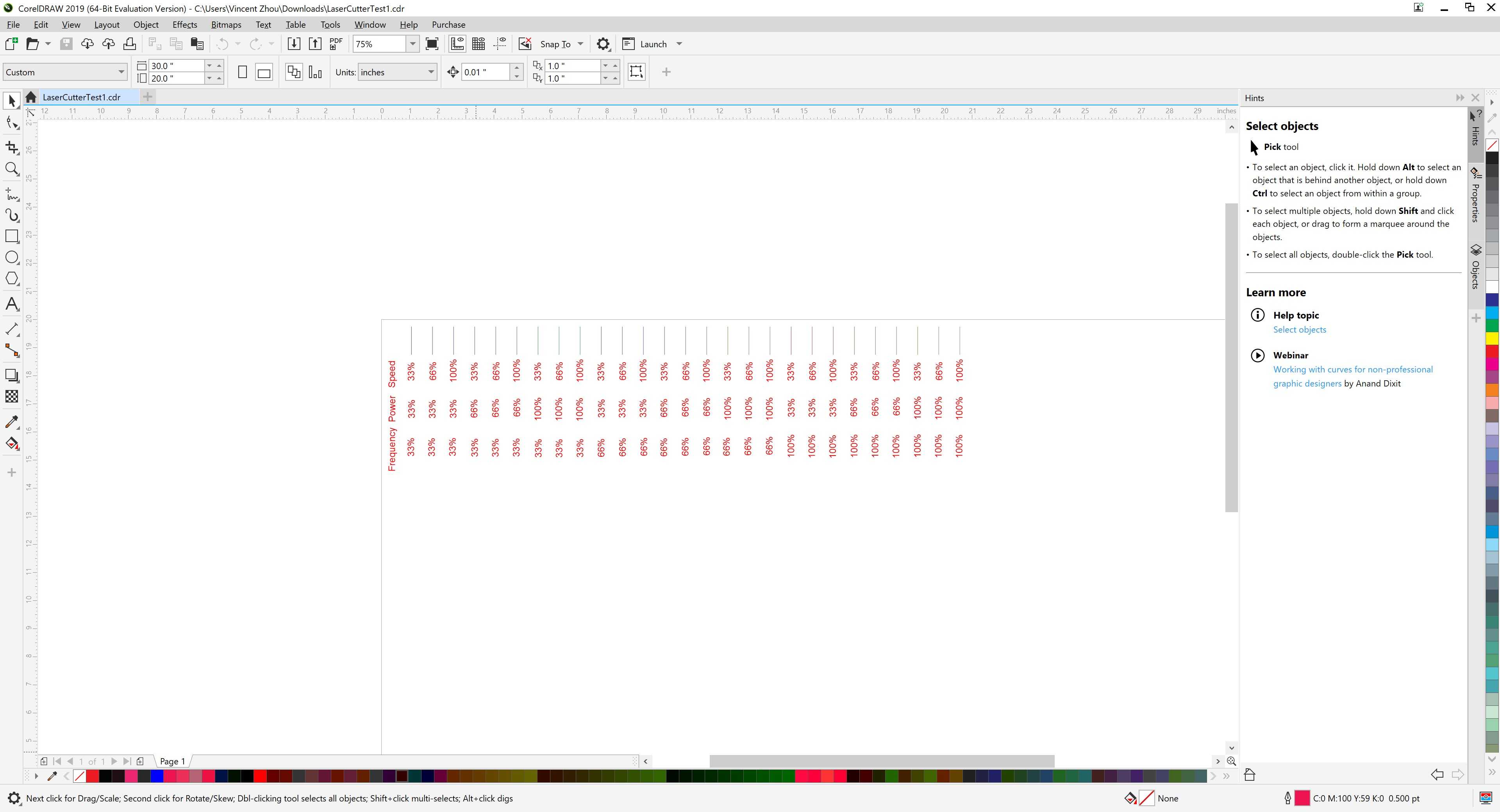
So, we decided to try all the combinations of the three in increments of thirds, at 33%, 66%, and 100% (this resulted in 27 combinations). We then color mapped all 27 lines and started cutting them. We also changed the color maps to match the settings. Red = matches the frequency setting Green = matches the power setting Blue = matches the speed Setting
We then cut and engraved the file on ¼ plywood rather than cardboard as this way, we could see the effects of each factor on the cut by seeing the darkness of the engraving and its thickness.
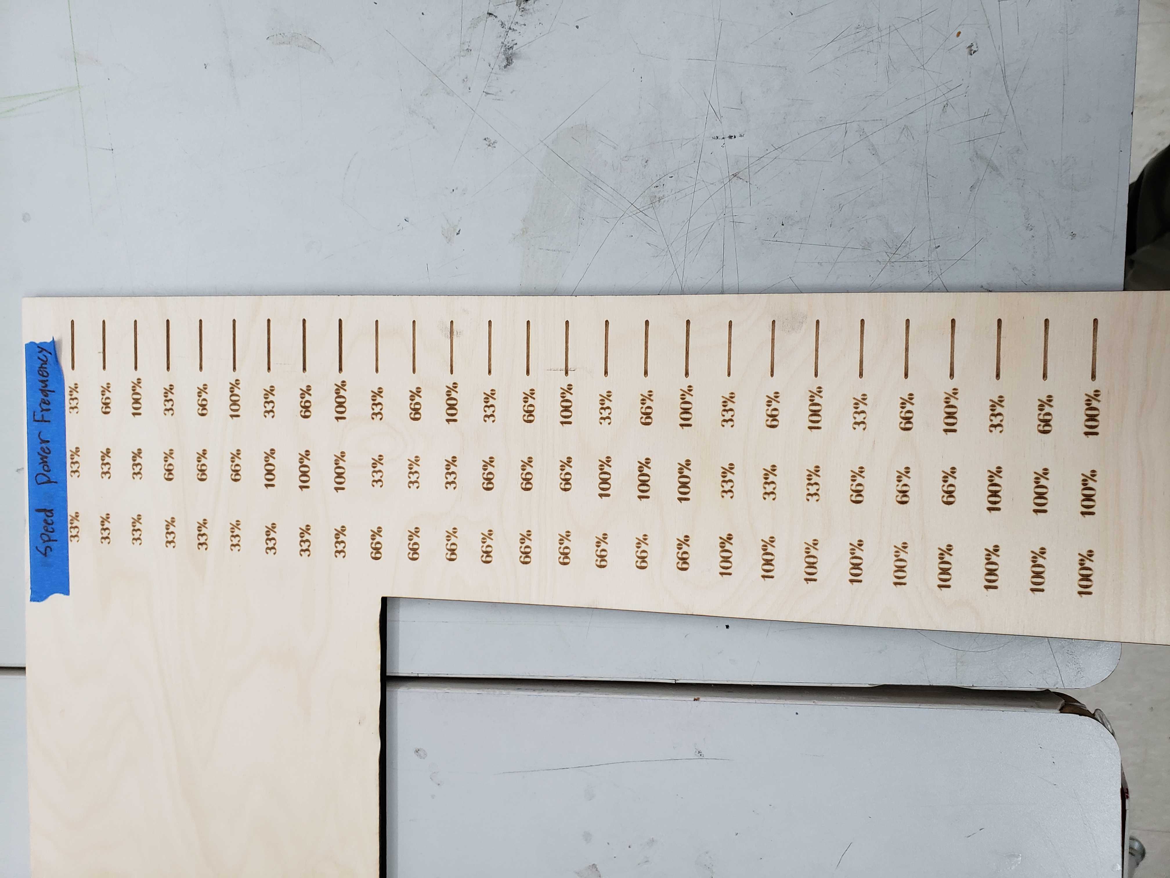
After analyzing this picture we came up with the following conclusions. Speed and cut depth had an inverse relationship. The higher the speed, the smaller the cut depth. Power and cut depth had a direct relationship. The higher the power, the greater the cut depth. Frequency and cut depth had a direct relationship. The higher the frequency, the greater the cut depth.
Determining Laser focus
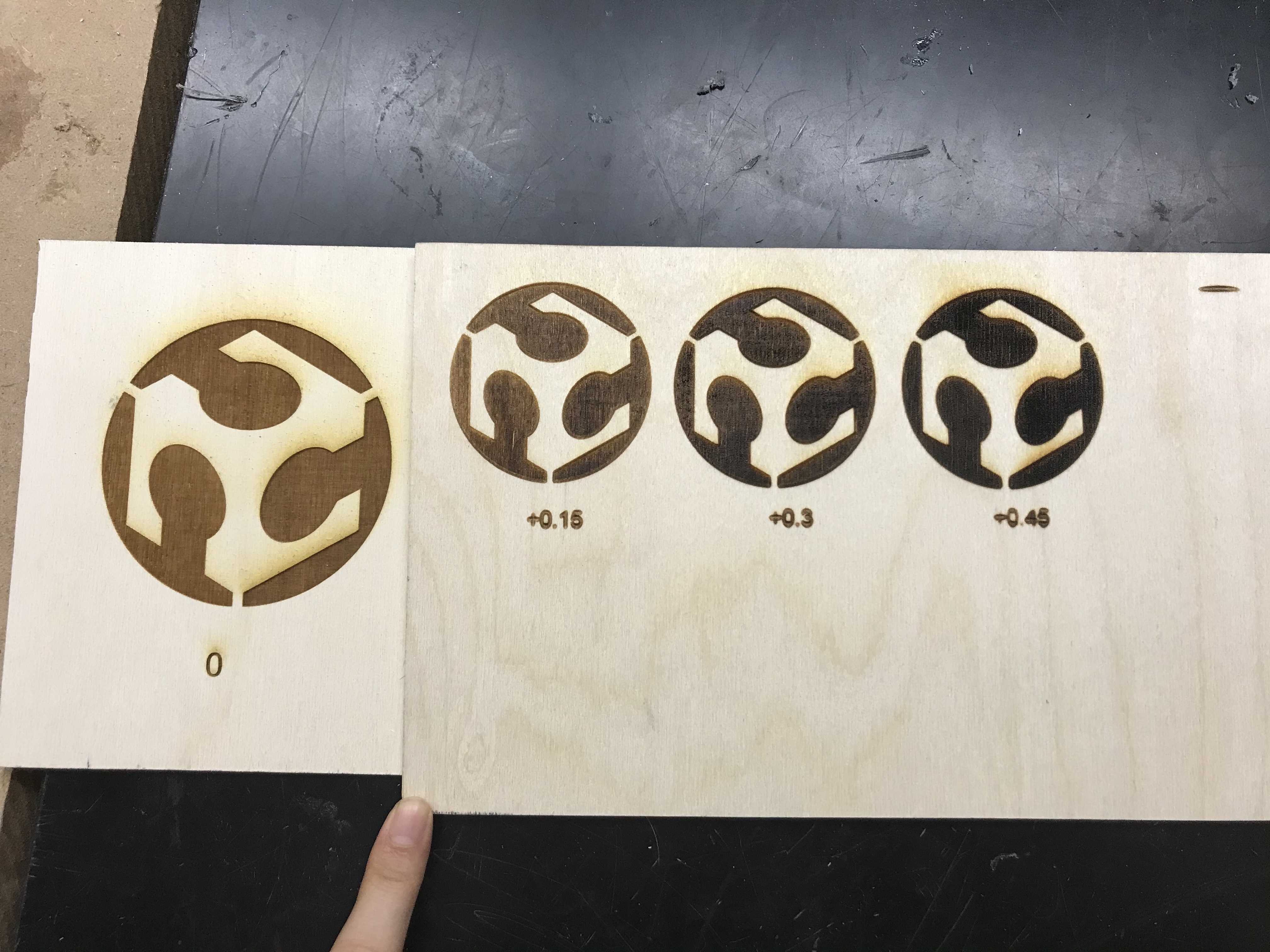
To measure laser focus we decided to cut more lines like we did with power speed and frequency. We made a series of 15 vertical lines, each a different color. A cut of each line was made, each with a different focus that corresponded with the color of the line. We ended up making 15 separate cuts with different focus intervals of 0.3. This way we could change the color of each line to be cut and change the focus each time. However, before we cut, we realized that it wouldn't be effective to see how different focus levels affect the material using just a line, so we decided to decrease the number of focus increments and instead engrave the FabAcademy logo. This lets us easily see how changing the focus changes engravings.
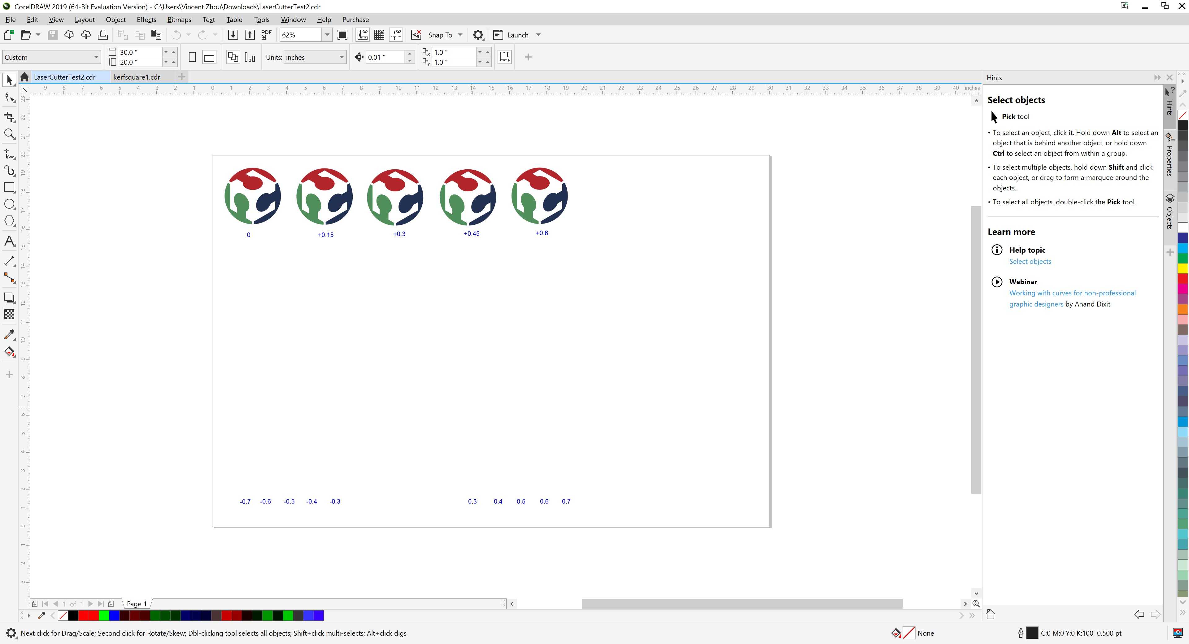
Ultimately, we determined that as the distance between the laser head and bed increased, the darkness of the engraving increased.
Kerf
Before this assignment, none of us knew what kerf was, so we had to look on multiple websites and consult our teachers to formulate a concise definition. However, because we did not know what it was to begin with, we obviously did not know how to calculate it. To figure this out, we, again, searched online. We found that many people, after subtracting the dimensions they got from their original design dimensions, divided by two. We found that this was unnecessary because each side of the square was half of the kerf. Since on each side the laser followed the line down the middle, each side's "kerf" was only half of the true kerf. To calculate the kerf, we only subtracted the dimensions we got from the design dimensions. In order to measure the kerf, we needed to find the difference between the length of a side of a square on a design file and the length of a side of the square that was cut from the file. We cut a 2in x 2in piece of plywood which we then measured with a caliper.

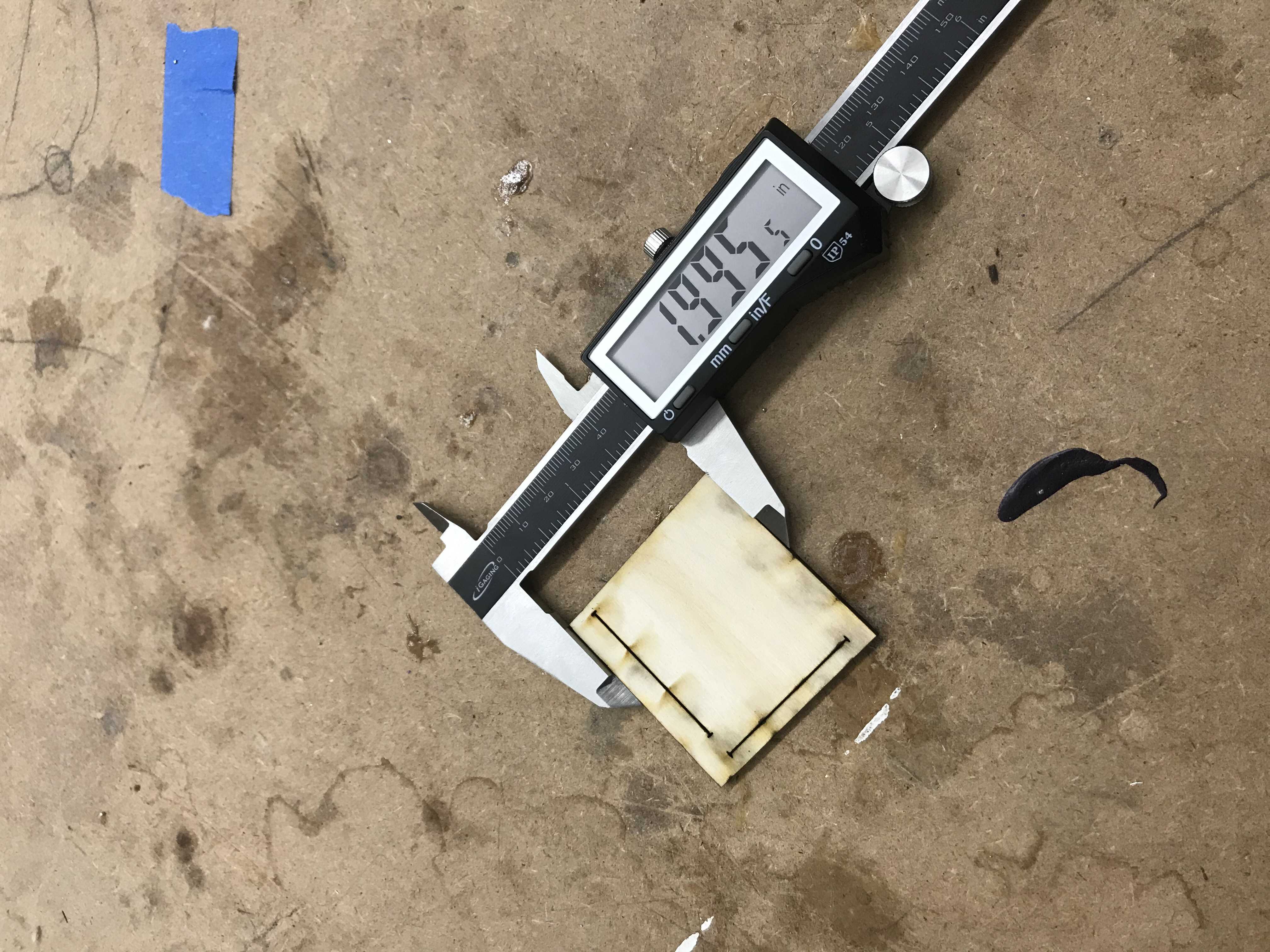
Design: 2x2 inches Actual: 1.995 in Kerf value: 2.000 in - 1.995 in = 0.005 in Knowing this is important because it will determine how tightly/loosely we want laser cut parts to fit together. Later, we may need to account for the joint clearance, as the joint clearance is the same as the kerf uniquely in the context of the laser cutter. When working with other machines, like the Shopbot, we understand that the kerf value will not be the same as the joint clearance.
Resources:
Disclaimer: we didn't make the two google docs above, but we did use them.