7. Computer controlled machining
This week we had to test runout, alignment, speeds, feeds, and toolpaths for our machine for a group project, as well as make (design, mill, assemble) something big for an individual project.
Group Project
For the group project, we had to test runout, alignment, speeds, feeds, and toolpaths for our machine. Specifically, I made the test files for any cuts made on Fusion360. I also defined some of the concepts for this week, like speeds and feeds. I also analyzed the cuts. Here is the link to our group project documentation.
Individual Project
This week, I had to make (design, mill, and assemble) something big. I thought of things I needed around the house, and decided to make a nightstand since I had just been tossing my phone on the ground each night when I sleep. This nightstand from Etsy gave me inspiration for my design.
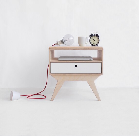
Designing
I first started with sketching out my design on paper, just to get an idea of how tabs would fit together and what dimensions I would use.


After I had a good idea of what my nightstand would look like, I started designing it in Fusion360. I started by making the parameters I needed, including the nightstand’s width, depth, and height, as well as any tab and clearance dimensions.

Then I made rectangles of the dimensions of the stand and added tabs along the sides. I had to plan out the tabs to fit together well. I also used some parallel constraints to make sure everything was aligned well.


For the bottom pieces and the legs, I had to match up a four-way tab. I first made a new set of parameters for the legs.

Then I made the two sets of legs using the parameters.


I made the bottom piece my copying the middle piece, adding a set of tabs on the sides, and adding the four-way tabs.

Then I extruded each piece by the material thickness value (0.75) and reorganized them.

I knew I needed dogbones, since the CNC wouldn’t be able to mill sharp corners on the inside. I had heard from other classmates that using Aspire would be much easier than making indiviudal circles for the dogbone, so I tried to use Aspire. However, after I imported my files into Aspire, Aspire would not let me dogbone the majority of my corners. So, Mr. Rudolph and I looked around online and stumbled upon a Fusion Add-in for dogbones. I downloaded the file, and closed and re-opened Fusion. The Add-in appeared in the Solid Create Section.

I found this add-in to be extremely easy to use. I tried clicking random buttons to see what would happen, and after a while I managed to understand how it worked. After clicking on the Dogbone icon, I just had to select a surface and the add-in would know which corners to dogbone. I could adjust these, but it accurately selected the corners I wanted.

However, sometimes I would find an error if I used the parametric mode for the dogbone (the circle with red triangles), so I switched to static dogbones if an error popped up. This ultimately did not affect anything.

The dogbones worked really well!
Prototyping
Now it was time to prototype. First I wanted to see if the legs and bottom piece would fit, so I used the align tool on Fusion to join the pieces. The pieces fit!


To prototype the nightstand in cardboard, I first projected all the bodies/pieces into different sketches. Then I exported each sketch as a DXF file.


I opened each file on CorelDraw, and first I joined all the curves of the sketches. Then I selected each sketch and reduced the dimensions of my sketch to 17.3%. I got this number by looking at the material thickness. The material thickness I had used in the parameter for the wood was 0.75. The thickness of the cardboard was 0.13. I did the calculation of 100/(0.75/0.13) = 17.3 to find out what percent I needed to change the sketches to. Then I cut each piece out on the laser cutter.


Each piece fit well together, but I still wanted to make the legs a bit wider, so I changed the parameter of the legtotalwidth to 2topheight/1.2 instead of 3topheight/2. This changed the width of the legs to 30 in.


Toolpaths
Afterwards, I made the toolpaths for the cut on Fusion360. I followed Mr. Rudolph’s, one of our teachers and fab instructors, tutorial. I separated my parts into two parts: the legs, sides, and top, and the bottom and middle piece. I made two setups for each.


Then, I made 2D Contour toolpaths for each. In the geometry tab, I selected all the bottom outlines I wanted to mill. In the Passes tab, I checked Roughing Passes and Multiple Depths. I set the “Maximum Roughing Stepdown” to 0.25 in and checked “Finish Only at Final Depth.” For any Pocket toolpaths, I selected the pockets I wanted to mill, unchecked “Stock to Leave” under the Passes tab, checked “Multiple Depths” and set “Maximum Roughing Stepdown” to 0.25”. Under the Passes section, I checked “Finishing Passes” and checked “Finish Only at Final Depth” under the Multiple Depths dropdown. Finally, I changed the ramp type to Plunge under the Linking tab. This is what the toolpaths looked like:


I also decided to make a new sketch of .25” holes on each piece so that I wouldn’t have to mill out tabs. I made around 4 holes for each piece and made drill toolpaths for each hole.

I then post processed each setup’s hole toolpaths and other toolpaths, giving me four sbp files in total. I went to Actions > Post Process and made the Post Processor ShopBot OpenSBP.
Setting up the Machine
I used a ShopBot PRSalpha to mill out my nightstand. I used this workflow that had been made by FabLab Director Mr. Dubick in years past.
1. Shopbot Machine
- Put on eye and ear protection
- Close the doors
- Check to see that the machine has been warmed up
- Check to see bit is not loose
- Measure the thickness of material that you plan to cut.
- Calibrate Z AXIS on the table. (C2 keyboard command)
- Raise Z AXIS 6 inches using the JZ 6 command
- Attach material to the table using screws
- Raise Z AXIS 6 inches using the JZ 6 command
- Use the proximity switch to set Calibrate. (C3 keyboard command)
- Set new X and Y Origins for your design
    - Raise the Z-axis so the bit won’t drag on the table
    - Using keyboard jog to the appropriate X and Y location. (J2 X,Y)
    - Using keyboard to zero the appropriate X and Y Location. (Z2)
    - You set origin.
- Select Cut
2. Start up Aspire and VCarve software
- Open your file
- Select objects you wish to cut
- Select Toolpath
- Pin Toolpath
3. Click on material setup
- Check Z - zero is on the bed, NOT the board
- Enter the thickness of the material *
    - Model position material should be the same thickness as the material.
- Click OK.
4. Go to TOOL PATH OPERATIONS
- Select 2D Profile Toolpath
    - Under cutting depth, select the cut depth of the material (CLS tools).
    - Select the proper tool -CLS down bit 1⁄4
    - Click add tabs and add tabs
    - Hit CALCULATE.
- Preview toolpath
- Click on CLOSE
- Select SAVE TOOL PATH and save the file in a shopbot format
5. Start ShopBot Command Console
6. Conduct air cut
- Select FILE-LOAD
- Load the appropriate file
- Select 1 3-D offset
- Press ENTER
- Turn on the spindle by pressing the big GREEN Button
- You should hear a “SOUND” of the spindle now turning
- Press ok
- After checking that everything is good; press space bar
- Select quit
- Return to origin (J2 0,0)
7. Perform cut
- Select FILE-LOAD
- Load the appropriate file
- Select no offset rather than 1 3-D offset
- Press enter
- Turn on the spindle by pressing the GREEN Button
- You should hear a “SOUND”
- Turn on the vacuum
- Press enter again to start cut
8. Cut is done
- Turn off vacuum (which is so loud you shouldn’t forget)
9. Clean up after yourself

It was then time to use the CNC machine! After I put on eye and ear protection and closed the doors, I switched out the bit that was in the machine for a .25” upcut bit. I then warmed up the machine by letting the bit spin.

I cleaned off and smoothed out the bed of the machine using sandpaper. I then jogged the Z-axis location to -0.01 using the MZ -0.01 command and zeroed the machine’s Y-axis position. I did this because the bed was not perfectly flat– some areas would mill more than others. Zeroing it here would ensure an even mill throughout the bed. Then, I took the piece of wood I wanted to use, a .75” inch piece of plywood, and moved it onto the bed. I drilled in screws in each corner to fix the wood to the bed.

I then jogged the Z position to 2 to prepare for a 3D offset toolpath test. After, I started to test out my hole sbp files. I clicked File > Load and selected my holes1.sbp file first. Then a screen popped up, and I changed no offset to 3D offset. I hit enter, then turned on the spindle by pressing the big GREEN button. I heard the spindle start up, and I hit OK on the screen. I expected the bit to hover above the wood and simulate out my hole toolpaths, but the machine just moved all the way to the end of the X-axis and stayed stuck. I hit the space bar and hit quit.
I realized that I needed to home the machine first before I started a toolpath. So, I moved to the origin (M2, 0,0) and then went through the process again. This time it worked. So, I went through the process again, this time keeping the offset as No Offset.
After all the holes were drilled, I used a drill to drill in screws in each hole. Then I went through the same process as I did for the holes1.sbp file as I did for my actual cut files.


After all the pieces were milled, I unscrewed all the screws and lifted each piece off the bed. After I got all the wood off the bed, I re-sanded the bed to flatten any bumps caused by the screws. I placed the second sheet of wood on the bed, and went through the file loading and starting process for the holes2.sbp file. After the holes were drilled, I drilled screws into each hole. I homed the machine, loaded in the actual cut files for the second setup, left it on No Offset, hit Enter, the green button, and OK.


When it was done, I unscrewed everything and got the pieces of my nightstand off the bed. Now I had to sand down the wooden fuzz on my pieces. I used an automatic palm sander to sand the edges.

After everything was sanded, I had the pieces ready to assemble!

I started with assembling the bottom piece and one side piece. I used a mallet and another piece of plywood (this was so that I wouldn’t dent my pieces). I gently hit the tabs together. When I felt that the tabs settled a little, I started to aggressively hit the wood (this was an interesting yet effective stress reliever in my opinion, even if it made my hand red and itchy). After the tabs fit snug and tight, I assembled the middle piece into the side piece. I then mallet-ed the other side piece onto what I had so far. I then added on the back side piece, topping everything off with the top piece. This took a lot of malletting, but it was pretty fun. (I’m sure my ears were wrecked by now, but it was all good). I ended the assembly process by adding the legs. This is what I got!


Here’s me sitting on it! Not going to lie, I was surprised that it was structurally sound enough to support a person:)

I liked this week more than the vinyl cutting week or the laser cutting week. I was able to create a large physical object that I could use on a day to day basis. Using larger scale tools like the CNC was more intimidating, but it was also more fun overall.
Files
Files used to make the toolpaths and prototype: week 7 files