13. Embedded Networking and Communications
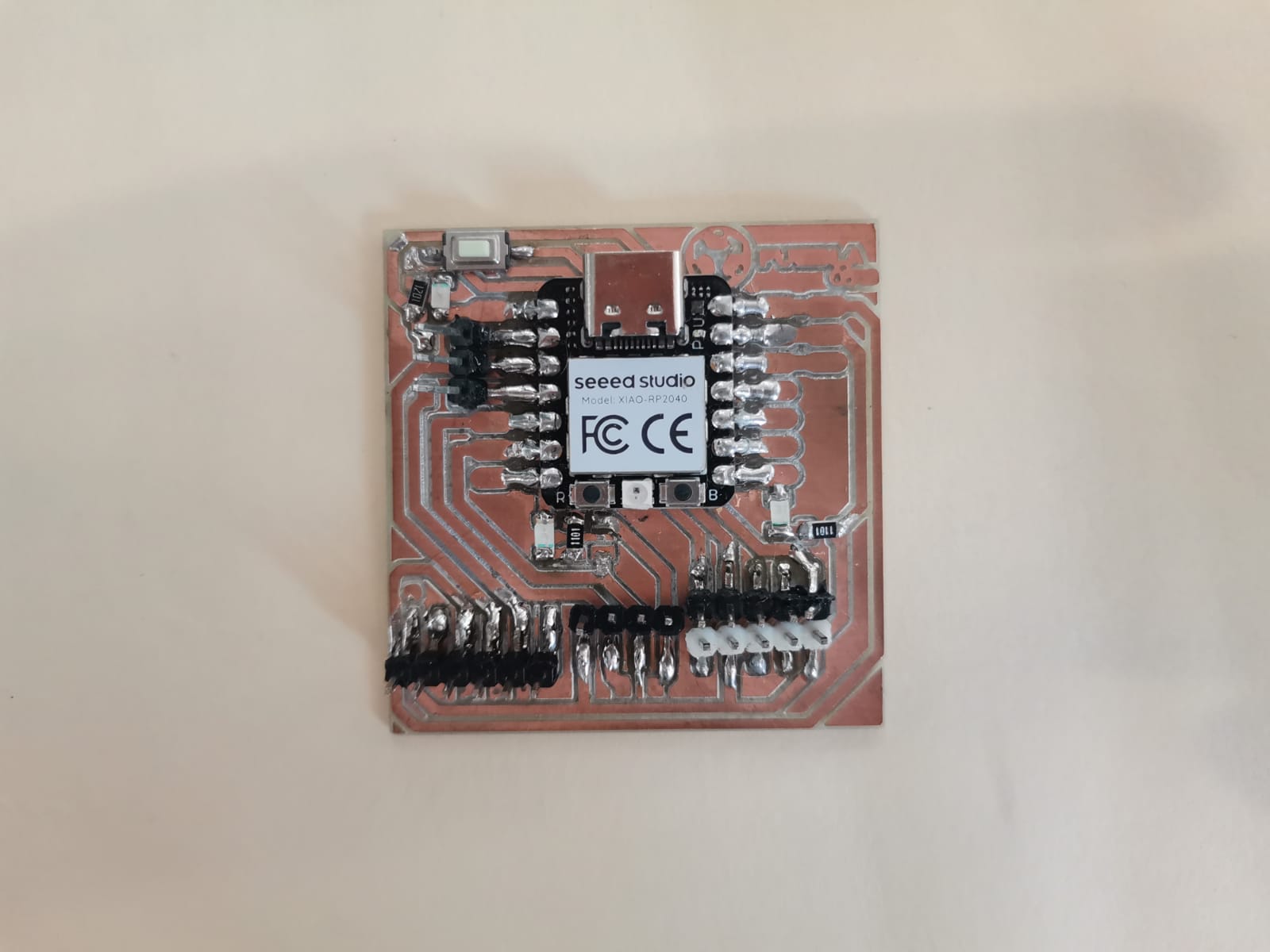
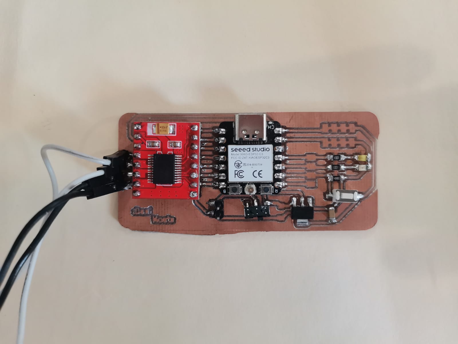
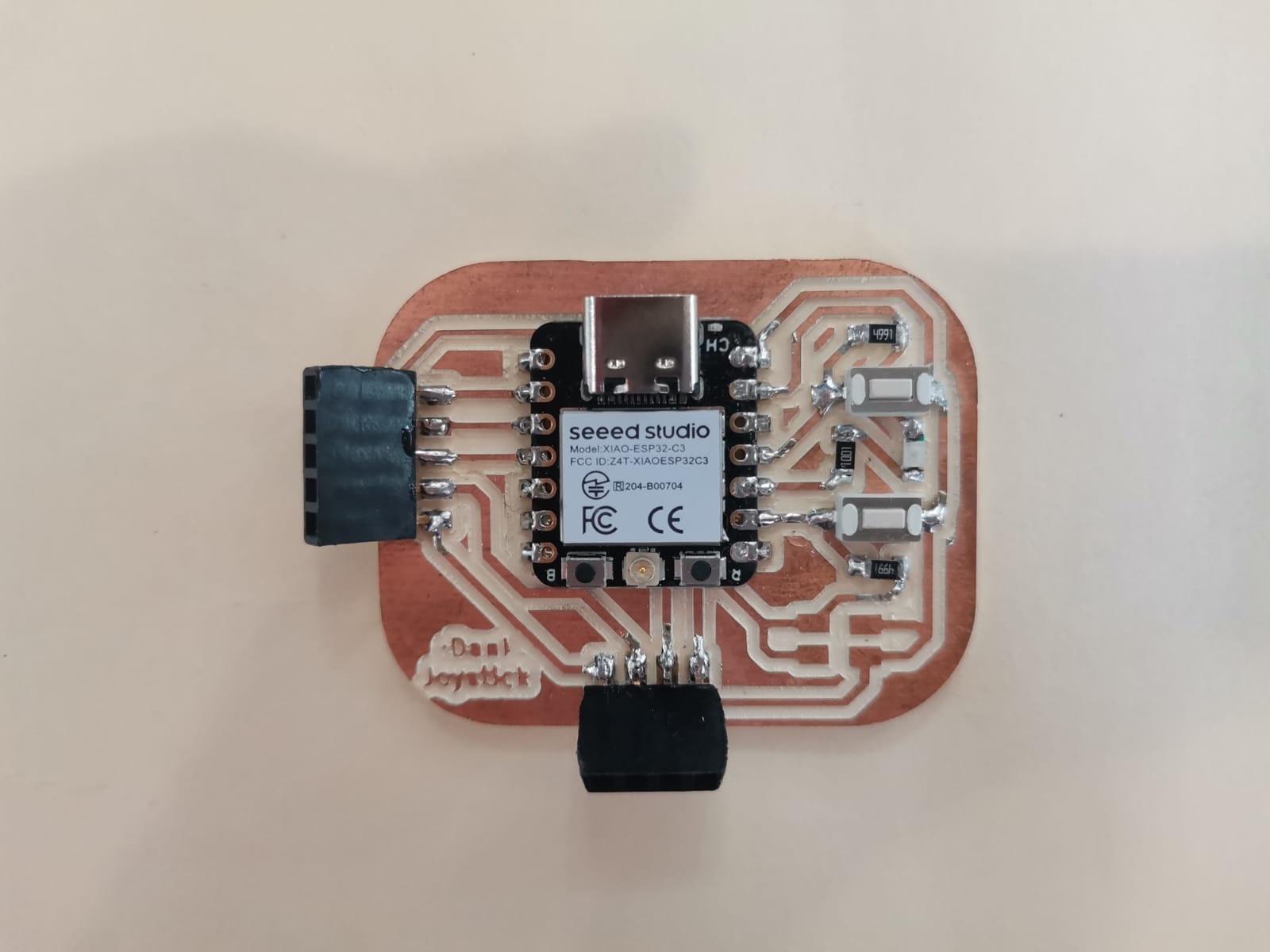
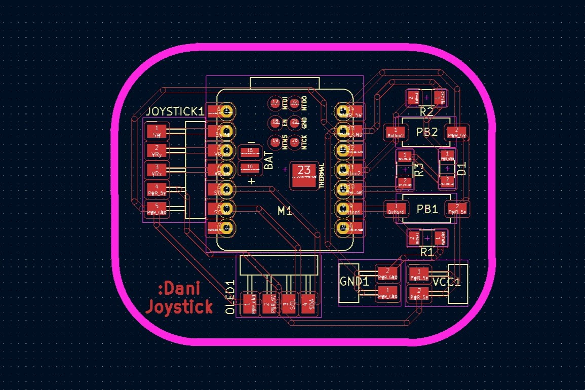
There are different ways of connecting microcontrollers between them (which can be observed in the group page), so for the task of this week I decided to use the Bluetooth of the Xiao ESP32-C3 to connect two of them and a wired connection for the Xiao RP2040. The boards I used are the following:
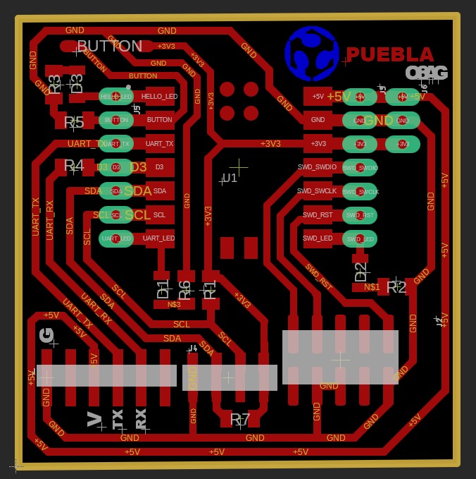
With their corresponding paths:

Types of Connection
There are different ways to make connections between microcontrollers. The type of connections that we learned in the local lesson are: UART, SPI, and I2C.
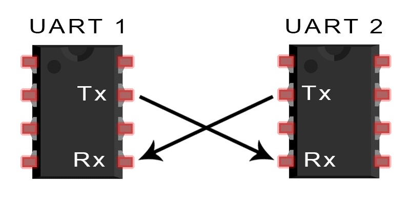
UART
The UART connection is an asynchronous way to send information between the microcontrollers and only needs two wires: one for sending the information (TX) and another one to receive the information (RX). For this type of connection to work it is important to establish both baud rates as the same for them to be able to read each other. It is also important to mention that the transmission wire (TX) of microcontoller A needs to be connected to the receiving wire (RX) of the microcontoller B as one will be reading the informtion sent by the other one.
SPI
The SPI connections is a synchronous way of sending information used mainly for peripheral devices. As a main difference with the UART connection, this uses four wires: MOSI (Master Out Slave In), MISO (Master In Slave Out), SCK (Serial Clock), and SS/CS (Slave Select/Chip Select). Also this type of connection is used with a Master-Slave configuration, where the master begins the communication and sends information to the slaves for them to perform different actions as a response to that information.
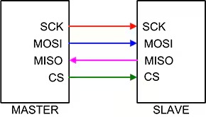
Image retrieved from: DigiKey
I2C
The I2C connection is used when a microcontoller needs to send different information to different slaves. This connection uses two wires: SDA (Serial Data Line) and SCL (Serial Clock Line). For it to make it work (send different information to different slaves), it is important to establish an address for each microcontoller.
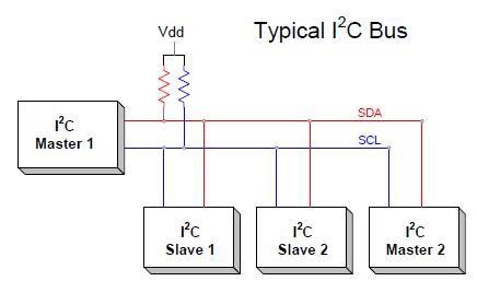
Image retrieved from: Research Gate
I2C Connection
The wired connection was between the Xiao ESP32-C3 and the Xiao RP2040 as master and slave, respectively. The communication between both boards was through an I2C connection using the SCL and SDA ports, as both of them have specific ports for that purpose. When using this type of communication, it is important to have a 1kΩ resistor connecting the 3V port with the SCL and SDA ports (only needed in one board); which is considered in the week 4 board. Both boards were connected though jumpers following the diagram:
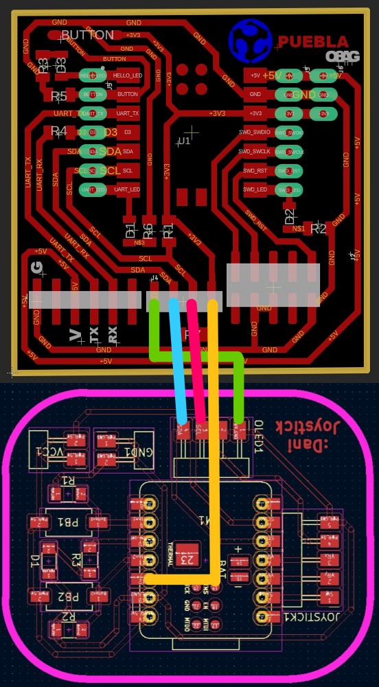
The left board is the one from the inputs week and the right one is the one from electronics production.
The master microcontroller sends information, while the slave processes it. In this case, the master send the information of the state of the push button and the slave receives it and decides what to do. For this code, it was something small in which the slave turns on a LED when it is pressed and turns it off when it isn't.
Master
Slave
Bluetooth Connection
The bluetooth connection was more difficult than I thought, but in the end, I beat it and was a pretty interesting experience. For this page to not be immensely huge, I will place the video and a link to download the file of the working process (with lots of comments explaining how it works). However, I will be explaining the final code of this subsection, where I connect 2 Xiao's and move a DC motor.
Getting Started with the Server
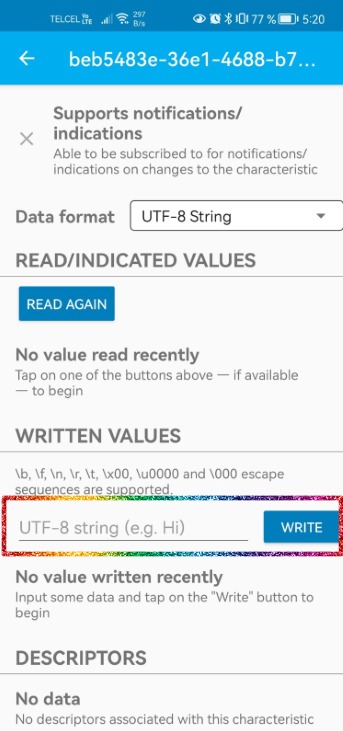
For the bluetooth connection I used two Xiao ESP32-C3 boards. First of all, I tried codes from the Seed Studio Wiki and used them to receive information using the phone (I followed the instructions from that page too, but I also explain them briefly here). With this I made the microcontroller to turn on and off a LED depending on the message sent. For this I followed the steps shown in the subtopic "XIAO ESP32C3 as Bluetooth server" and changed a bit the code uploaded to the microcontroller (the downloadable below the video):
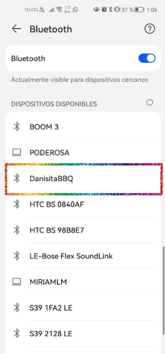
- I opened the Bluetooth settings in my phone and bonded the phone with the Xiao.
- After that I downloaded the LightBlue app in my phone.
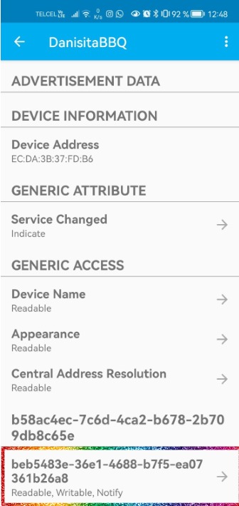
- In the LightBlue, I went to the Bonded section and clicked the Connect button from the Xiao device. (NOTE: if the microcontroller doesn't appear here, but you're sure you did bonded your phone to it, just turn on and off the phone's bluetooth.)
- From there on I had to go into the Readable, Writable, Notify section at the bottom.
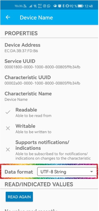
- Finally, I changed the Data format to UTF-8 String, wrote the messages and clicked in the "Write" button
to send it.
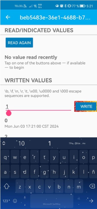
I named the microcontroller as "DanisitaBBQ" just for fun and used it. In this case, the Xiao only receives information and does something in response to that information.
Server Sending Information to Phone
After observing that the phone was able to send information via bluetooth to the Xiao, I tried to make the other way around (Xiao -> phone). Mainly because that's what would be happening in the final project. The code of this section still turns on and off the LED, but I added a onRead function to the code so that it would send something. For this practice I connected the joystick, since it is the one that will be sending information in my final project.
The code works in the following way: the microcontroller reads the signal from the joystick and assigns a word according to its position and then it sends a value with the pCharacteristic->setValue(Joy); command, where Joy is the string variable for the direction. Then, that string is read by the phone to show it in the screen.
Connect Two Xiaos and Move DC Motors
In this subsection I looked in another Seed Studio Wiki about bluetooth exchange from a server to a client. The wiki is mainly about a server that uses a light sensor and sends the sensor's information via bluetooth to the client. At first I only took the examples as a base for the code I already had from the 2 previous examples and ended with a server and a client code that didn't quite fit to each other.
At first, my main problem was that I wasn't able to bond both microcontrollers together. When I finally did that, the main problem was that the client couldn't read what the server was sending and the server didn't quite send the notifications (nor to the phone, nor to the other Xiao). As I was thinking of a solution for that, I came to the conclusion that I needed to be constantly sending notifications, and therefore a piece of code that was repeating itself. In the beginning I was sending the notifications only through the callbacks class, but it wasn't repeating itself. Then I knew I needed something in the main loop (it may sound a bit dumb that I didn't think of it from the beginnig, but the first wiki had nothing in the main loop and had any problem). As I was writing the solution for the code, I concluded it would be pretty similar to the one of the second wiki and just took that and adjusted for the motors and joystick.
Finally, there are two codes: the server and the client. The server's purpose is to process the values form the joystick and send them; while the client's purpose is to connect itself to the server, subscribe to its notifications and move the motors according to the signal read.
Connect 2 Xiaos and send information from server (.ino) to client (.ino)
Here the problem is that there is only one motor, but it is because I killed one tab from the other motor. However, the change in direction according to the joystick signal is appreciated.
Some main Errors/Messages
While programming and doing the tests, I encountered some problems. These are classified due to where is the problem shown and which is the error:
| Where? | Problem Message/Error | Solution |
|---|---|---|
| Phone | No data available: failed to establish connection to device, please select another device or try again | Press Xiao's reset button |
| Arduino IDE | Failed uploading: uploading error: exit status 2 | Follow the next steps: 1. Press the reset button. 2.Press boot button while still pressing reset. 3.Stop pressing reset button. 4.Stop pressing boot button. 5.Upload code. 6.Press reset. |
| Arduino IDE | Failed uploading: uploading error: exit status 1 | For some reason, the joystick was making kind of an interference. I disconnected the joystick and it was able to be uploaded. |
Joining I2C + Bluetooth
The final part of this week is to join the I2C and bluetooth connection together. In this case, the master is the joystick board (Xiao ESP32-C3) and is connected through I2C to the RP2040 and through bluetooth to the other Xiao ESP32-C3. This activity was mainly to observe how the same signal form the joystick is sent through different types of communications to a different board. For this I only turned on and off a LED as it was merely out of curiosity. I also used the same slave code from the I2C connection, but changed the server (to send I2C and bluetooth signals) and client (to only turn on and off the LED when the joystick isn't in the center) codes from the bluetooth:
Server/Master
Client
This time the three boards are shown to observe how the master (the joystick's board) sends the information through the both methods (I2C and bluetooth). Here it is observable that I already did the case for the joystick in the final project, si it was also easier to notice the wired and the wireless communication.