My Final Project
The idea for my final project is an aadaptable motor for wheelchairs. Its purpose is to push the wheelchair using a motor so that the user may be able to do other activities involving the hands.
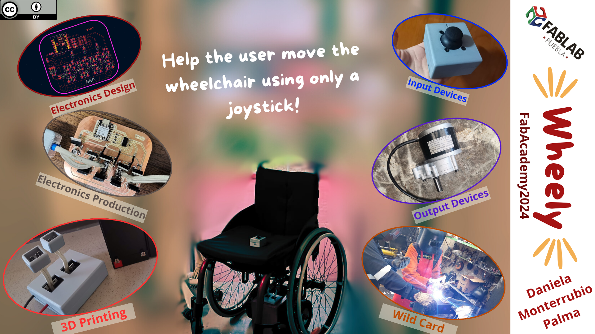
Slide and Video
Frist, the final slide and video to show more or less what's all this about:
Slide
Video
Internet Research and Tentative Sketch
The idea of working on a wheelchair began when I saw this Instagram reel and kept thinking about it. Since I study Biomedical Engineering, I thought that could be a great projet to develop. The video made me realise that there is a problem for people with disabilities and/or their carer when they have more things to do. Also it is uncomfortable for wheelchair users to keep pushing the wheelchair all the time.
Some of the existing wheelchair motors are the following:
For this project I am still deciding if using one or two wheels. I think I will be using two, as well as two motors to move them and give direction to the wheelchair. Also, it is going to need tubes to attach the wheels to any type of wheelchair, because not all of them have a horizontal tube at the back. The importance of having two new wheels and not using the ones of the chair itself is that not all of the wheelchairs' wheels are accesible. So there is no way to control those wheels without modifying the wheelchair and maintain the project as an adaptable motor. I find it important for it to be adaptable as a lot of people already have a wheelchair and it is not possible for them to afford an electric wheelchair.
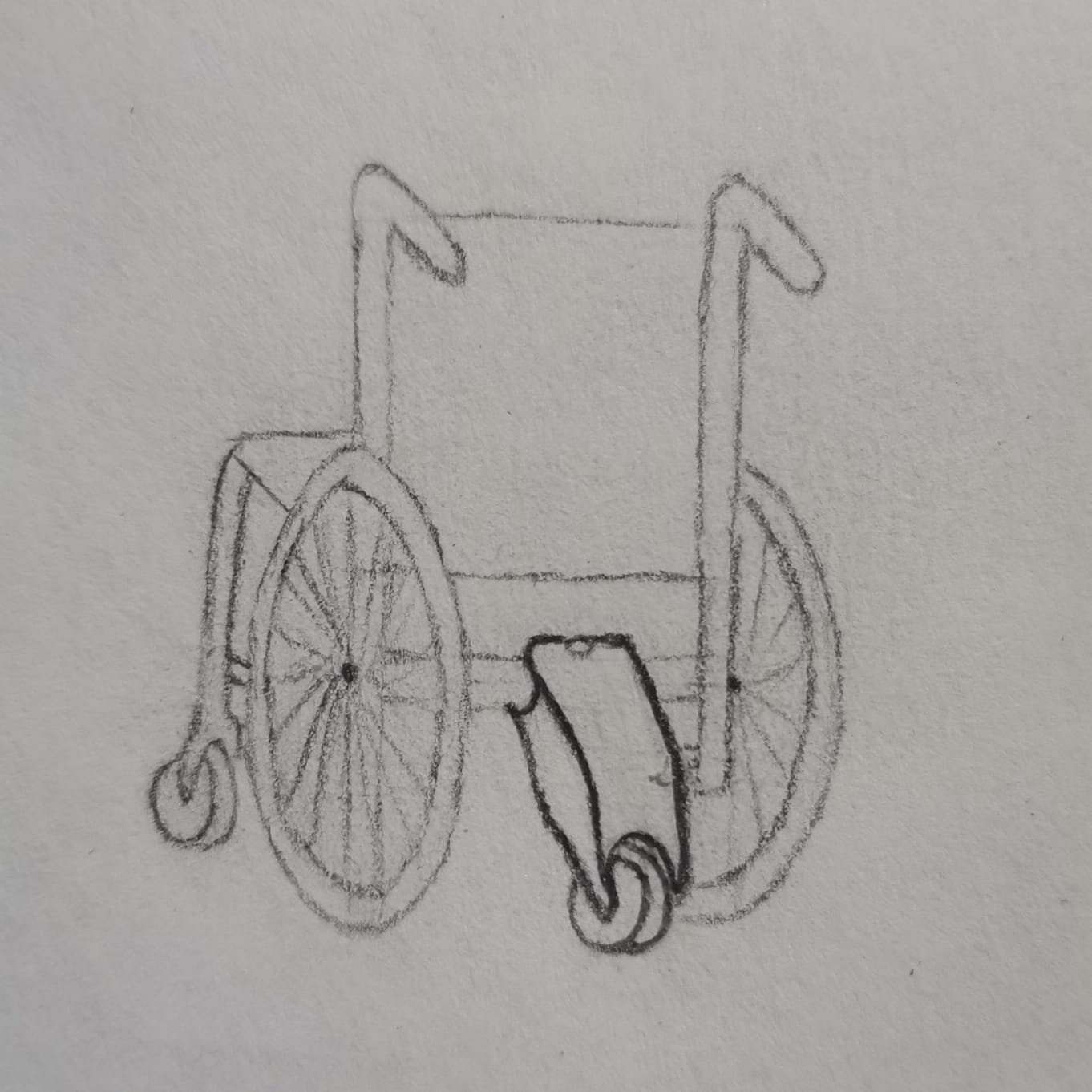
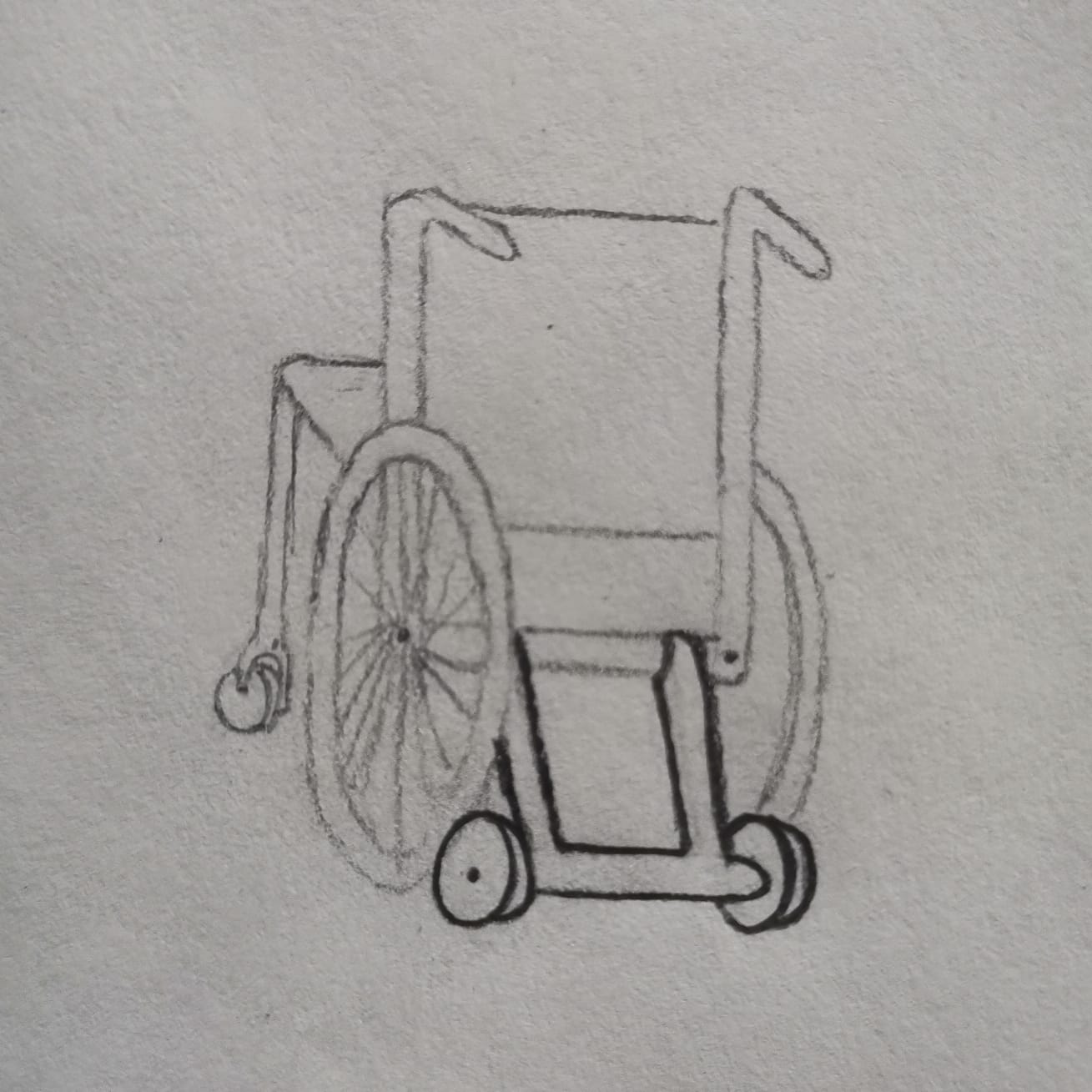
First Sketch (31/01/2024)
I have two tentative sketches, one for each of the ideas (one or two wheels).
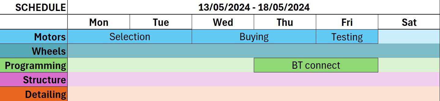
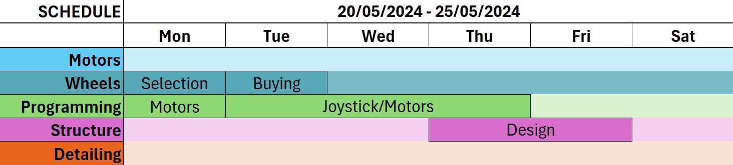
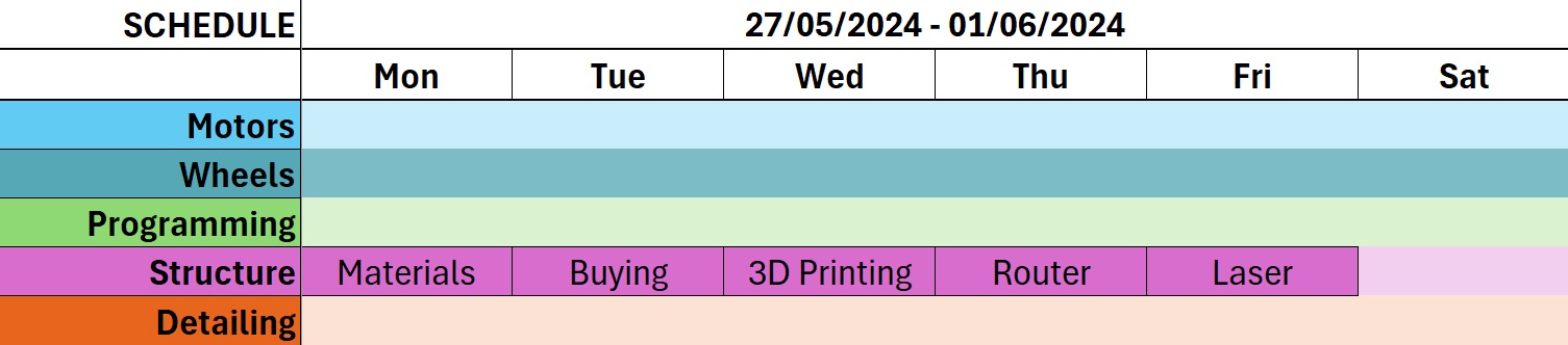
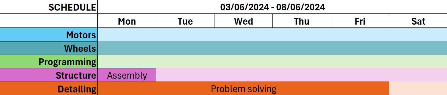
Schedule
In order for all to work (or at least to have a plan), here is a little approximetaly schedule for the tasks I will be doing for the proyect.
More Research
About the Wheelchairs
To know more about the wheelchairs I went to the Biomedical Engineering Laboratory to observe the wheelchairs that are there. In the classroom I found that some of them have a middle bar and some others don't:
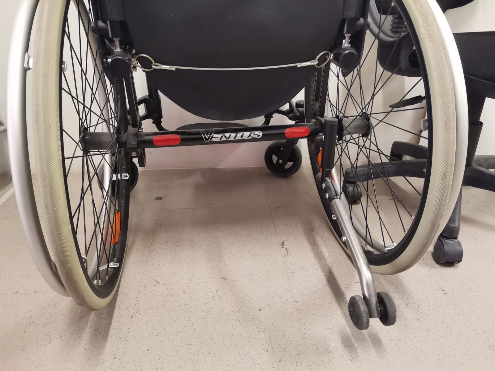

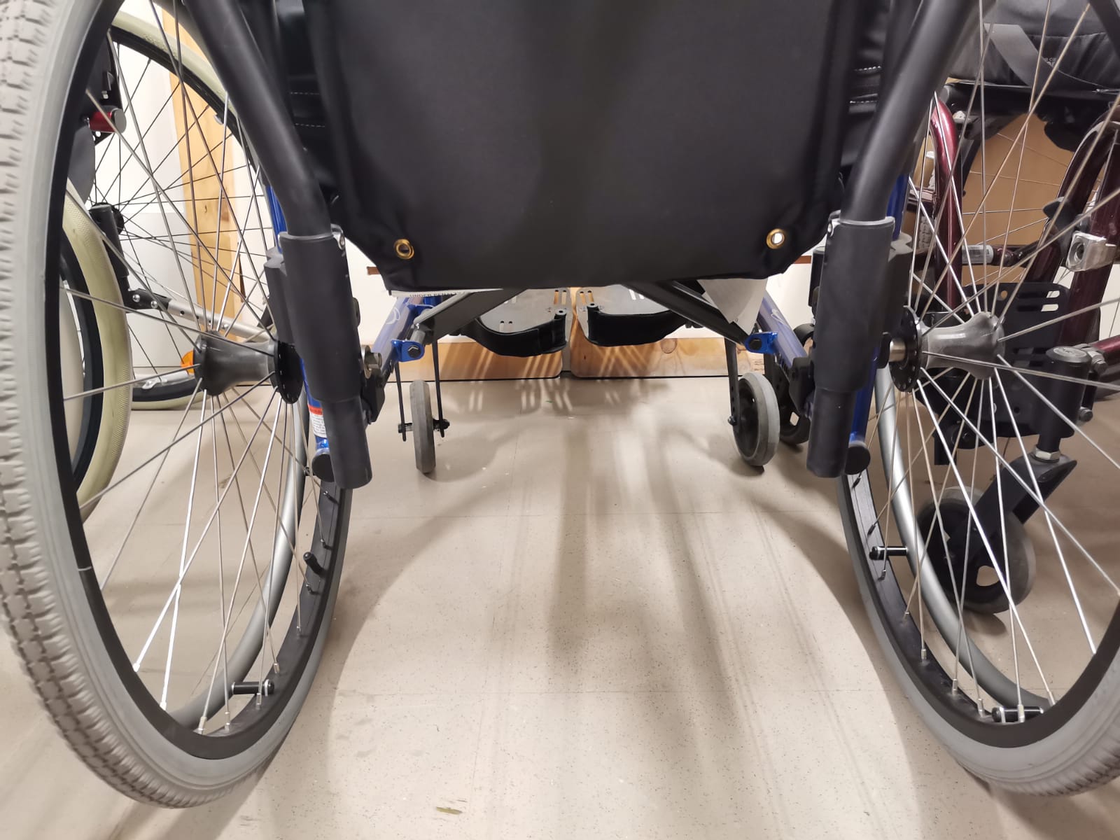
For that reason I had to change some aspects of the sketch.
Motor Calculations
The users would be mexican people (I'm from Mexico :D), so I based on this to know how much weight the motors are going to be exposed to. According to INEGI (National Institute of Statistic and Geography or Instituto Nacional de Estadística y Geografía), the average weight of mexican people is between 68 and 74 kg. Although that's the average weight, I considered a weight of 90 kg, a wheelchair weight of 15 kg and a sistem weight of 10 kg, giving a total of 115 kg that would be carried by the motors.
I also searched for the weight supported by already existing wheelchair motors:
- Power Pack Plus: 159 kg
- Empulse R20: 190 kg
- JQ-B2 Moving Booster: 100 kg
I considered gearmotors since they already have the gear system to improve the power. To know how much torque I would be needing from the gearmotor I had to make some calculationsb based on a thesis (from where the free-body diagram is too). These calculations were done considering the following information:
- Desired speed (v): 2 m/s
- Max. ramp angle (θ): 6.88° (0.12 rad)
- Considered wheel radius (R): 0.1 m
- Rolling coefficient (Crr): 0.02
- Wheelchair mass: 15 kg
- Considered person mass: 90 kg
- Approx. prototype mass: 10 kg
- Total mass: 115 kg
- Total weight (W): 1,128.15 N
Then, the free-body diagram is the next one:
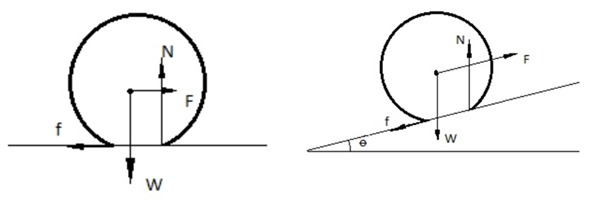
The diagram showed that the force needed to move the wheelchair up a ramp obeyed the formula F=CrrN+Wsinθ due to the needed component of the normal force and the component from the weigh. First, the calculation of the normal force:
N=W cosθ
N=(1,128.15)  cos(0.12)
N=1,120.03 N
Then the required force to move the wheelchair up the ramp:
F=CrrN+W sinθ
F=(0.02)(120.03)+(1,128.15)  sin(0.12)
F=157.542 N
Since each gearmotor would be carrying half the weight, the force would also be distributed among both gearmotors, and each would be exposed to 78.771 N. The torque needed from each motor goes as follows:
T=FxR
T=(78.771)(0.1)
T=7.8771 Nm
Finally, the power form the motor obeys the formula P=ωT. Where ω is the angular speed:
ω=V/2πR
ω=2/2π(0.1)
ω=3.1831 rev/s=190.986 rpm=20 rad/s
Once the angular velocity is calculated, the power goes as follows:
P=ωT
P=(20)(7.8771)
P=157.542 W=0.211 Hp
About Motors
There are different kind of motors, but the ones I'd be using are DC motors, because they are easier to control. However, it is important to know exactly which motor is the one perfect for the project, so I researched about them taking into account the previous calculations for the torque, power and angular speed. Finnally, I decided to buy the 2nd motor of the table.
| Internet Gearmotors | Power | Angular Speed | Supply Voltage | Price (mxn) | Arrival |
|---|---|---|---|---|---|
| 1° (amazon) | 350 W | 3,200 rpm | 24 V | $1,929 | 1 day |
| 2° (amazon) | 250 W | 75 rpm | 24 V | $749 | 2 days |
| 3° (ebay) | 250 W | 74 rpm | 24 V | $2,009.88 | 2 weeks |
| 4° (ebay) | 250 W | - | 24 V | $1,544.22 | 1 month |
| 5° (amazon) | 350 W | - | 24 V | $1,695.03 | 1 month |
Materials
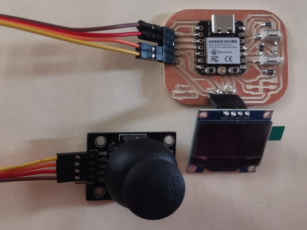
Joystick PCB
Here are listed the necessary parts for the joystick to work as desired, omitting the ones not used in by the project. This PCB was done during the inputs week.
| Qty | Description | Price (each) | Link/maps location |
|---|---|---|---|
| 1 | Xiao ESP32-C3 | $92.52 MXN (plus taxes) | DigiKey |
| 1 | LED smd | $3 MXN | Local electronics shop |
| 1 | Resistor 220 Ω | $1 MXN | Local electronics shop |
| 1 | Joystick module | $150 MXN | Local electronics shop |
| 1 | Switch | $20 MXN | Local electronics shop |
| 1 | Charging module | $39 MXN | Local electronics shop |
| 1 | Lipo battery 3.7 V | $90 MXN | Local electronics shop |
Joystick Case
| Qty | Description | Price (each) | Link/maps location |
|---|---|---|---|
| 200 gr | PLA | $346 MXN (per roll) | Inovarket |
| 4 | Screws 3mm x 16 mm (for the joystick) | $2 MXN | Local screw store |
| 2 | Screws 3mm x 6 mm (for the switch) | $2 MXN | Local screw store |
| 6 | Nuts | $0.50 MXN | Local screw store |
Motors PCB
| Qty | Description | Price (each) | Link/maps location |
|---|---|---|---|
| 1 | Xiao ESP32-C3 | $92.52 MXN (plus taxes) | DigiKey |
| 1 | LED smd | $3 MXN | Local electronics shop |
| 5 | Resistor 220 Ω | $1 MXN | Local electronics shop |
| 4 | Resistor 11 kΩ | $1 MXN | Local electronics shop |
| 1 | Optoisolator | $20 MXN | Local electronics shop |
| 4 | Transistors SQM40031 | $30 MXN | Local electronics shop |
| 4 | Transistors IXTA340N04T4 | $30 MXN | Local electronics shop |
| 1 | Capacitor 220 uF | $15 MXN | Local electronics shop |
Motors Case
This case was done during wildcard week.
| Qty | Description | Price (each) | Link/maps location |
|---|---|---|---|
| 1 | Metal sheet 30 cm x 60 | $300 MXN | Any lathe workshop |
| 2 | Metal beam | $20 MXN | Any lathe workshop |
| 2 | Metal studs | $10 MXN | Any lathe workshop |
| 1 | Metal spray paint | $60 MXN | Any hardware store |
Motors' PCB Case and Plugs
| Qty | Description | Price (each) | Link/maps location |
|---|---|---|---|
| 300 gr | PLA | $346 MXN (per roll) | Inovarket |
| 4 | Male (for motors) and female (for battery) spade connectors | $6 MXN | Amazon |
Regarding the Joystick
Regarding the PCB for the joystick part I worked on that during the Inputs Week and used the same code as in the the Networking and Communications Week to send the information from the joystick:
With its corresponding schematic and board design:
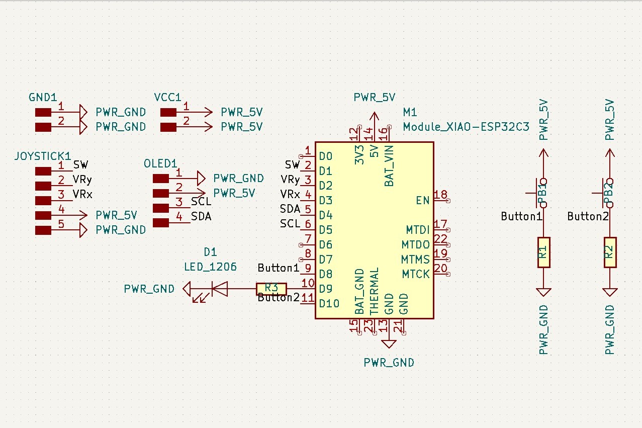
Schematic design
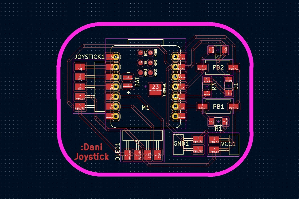
Board design
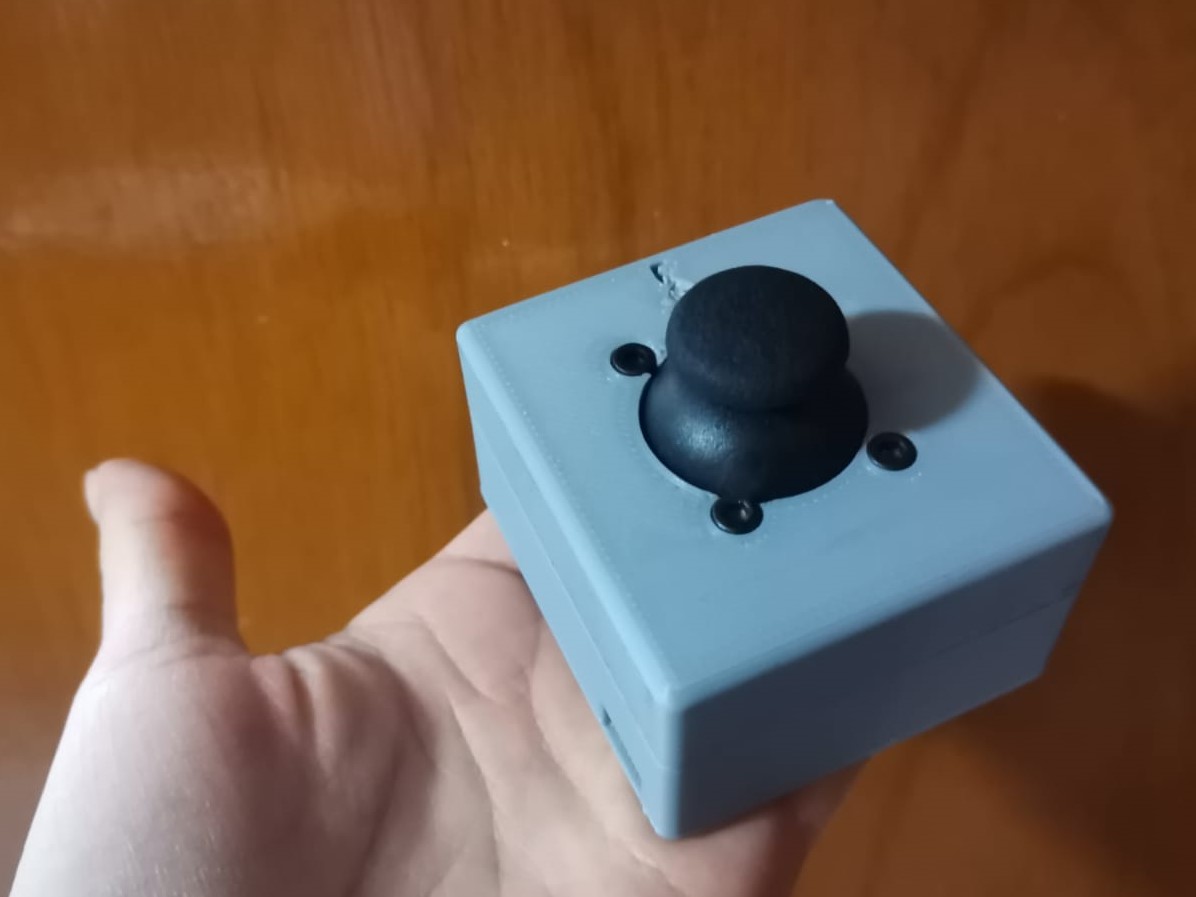
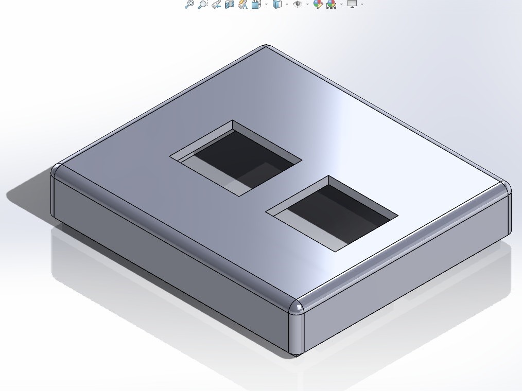
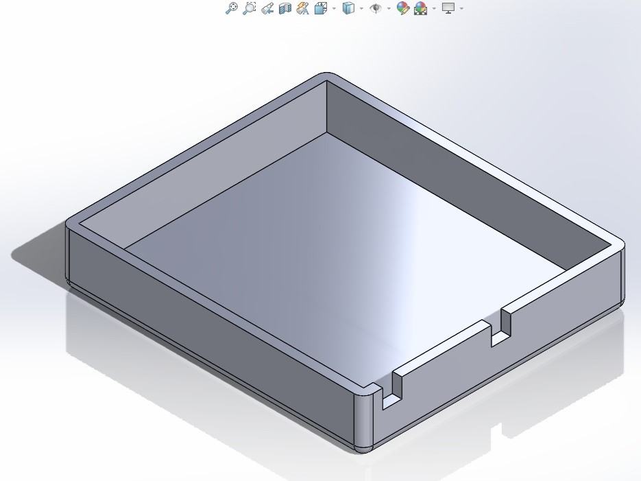
Case
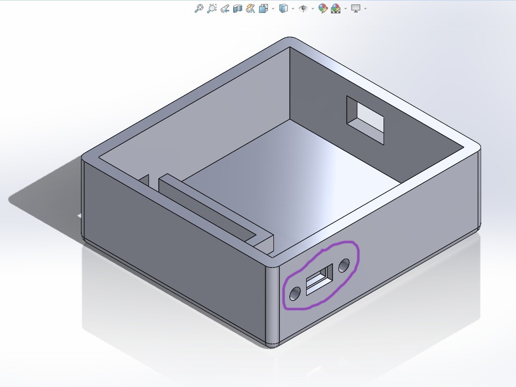
Having ready the PCB, the next step is to create its own case to make it easier to use it. First of all, I needed to know all the components that will be inside the case, such as a battery, its charger and a switch for it to not be turned on forever. Then I arranged the objects in the place I found it more practical and designed a case to surround everything. I designed the case in Solid Works and exported it as STL file. Then used Bambu Studio to create the 3mf file to print it in the Bambu printer. The process to create the 3mf file is the same as in the 3D Scanning and Printing week.
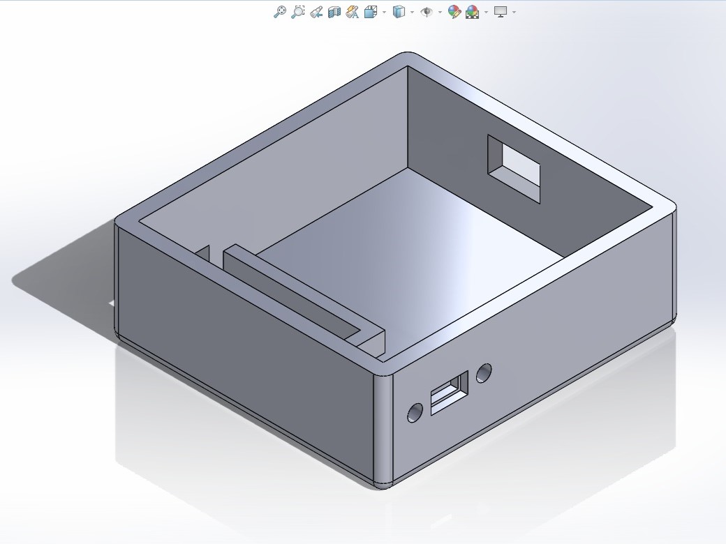
Base case design
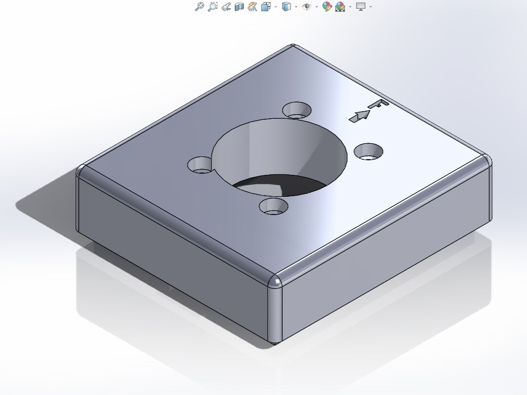
Lid case design
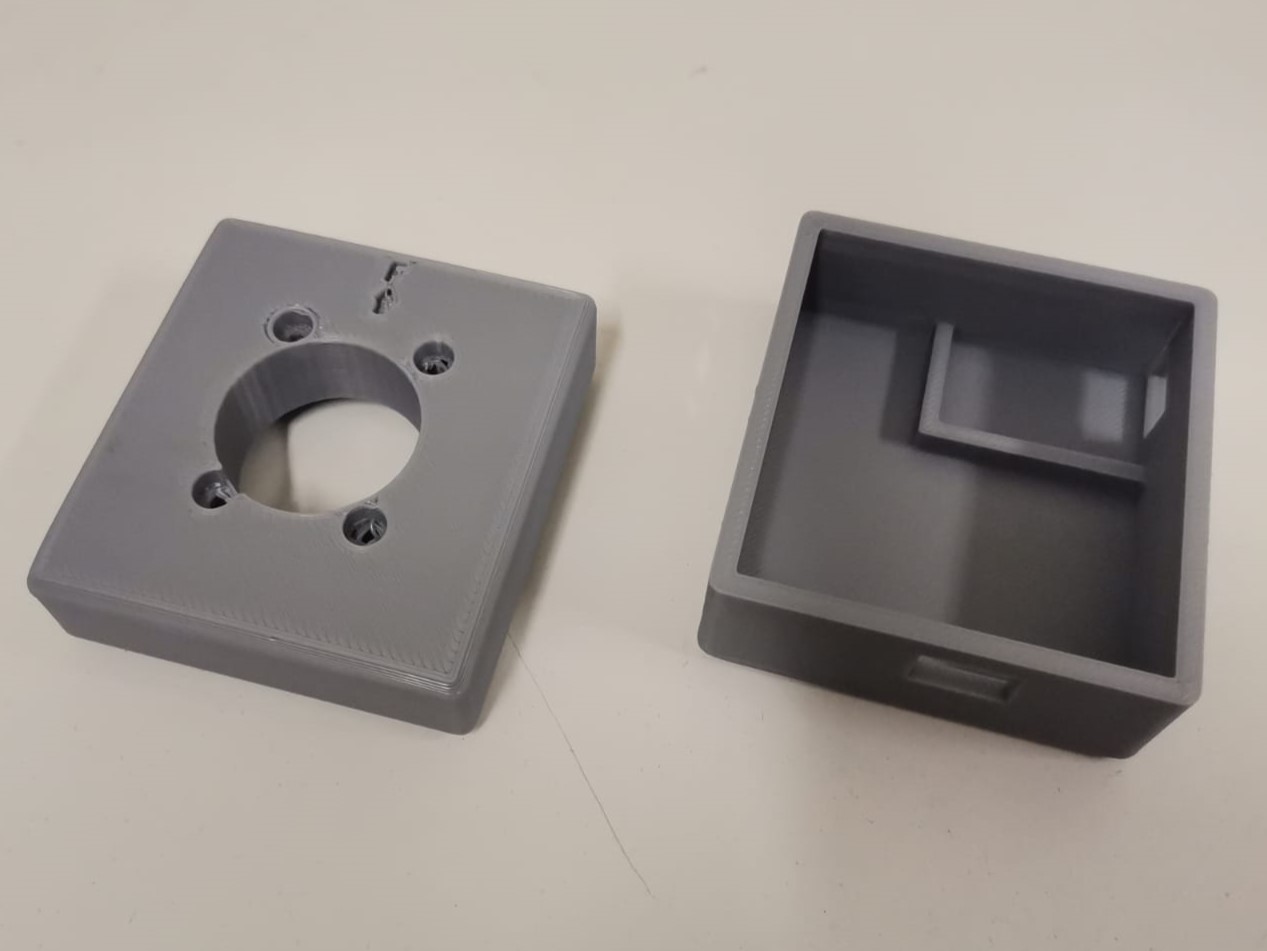
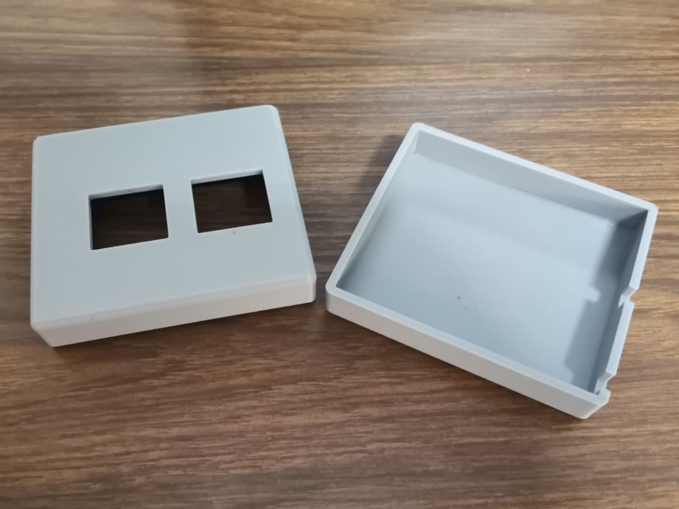
Printed case
After having the case printed I checked that both parts assembled well. When trying to fit everything in, it wasn't quite easy in a random way, so I placed everything inside in the next order:
- Paste the battery to the back of the PCB with double-sided tape.
- Conected the battery to the charging module, taking into account that the battery's ground has to be connected to
the B- and the voltage cable to the B+.
The main reason to use an external charging module is that the PCB was ready to be used, but I didn't consider the battery from the beggining. As I didn't consider the battery and didn't leave access to the battery ports from the Xiao (I would have had to desolder the Xiao and didn't want to risk it), I had to use an external charging module.

- Connected the charging module to the PCB. However, only the OUT- is connected directly to the PCB's ground; while the OUT+ is connected to the middle pin of the switch and one of the right pin of the switch goes to the PCB's voltage. In the case of my PCB it has to be connected to the 5V port from the Xiao since it is the only voltage port that has space as extra pinheaders, but it might as well be connected to the 3V3 port if it was considered from the beggining when designing the board.
- Screwed the switch to the base of the case.
- Placed the battery and the PCB in the big space of the base.
- Placed the charging module in the small space making the type C input to face the little hole.
- Placed the joystick in the lid.
- Screwed the joystick using the holes in the lid.
- Closed the case.
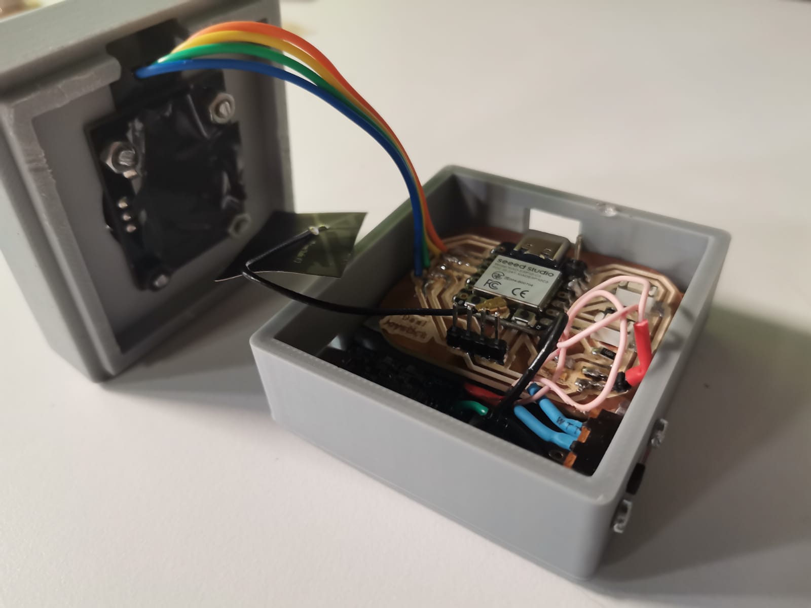
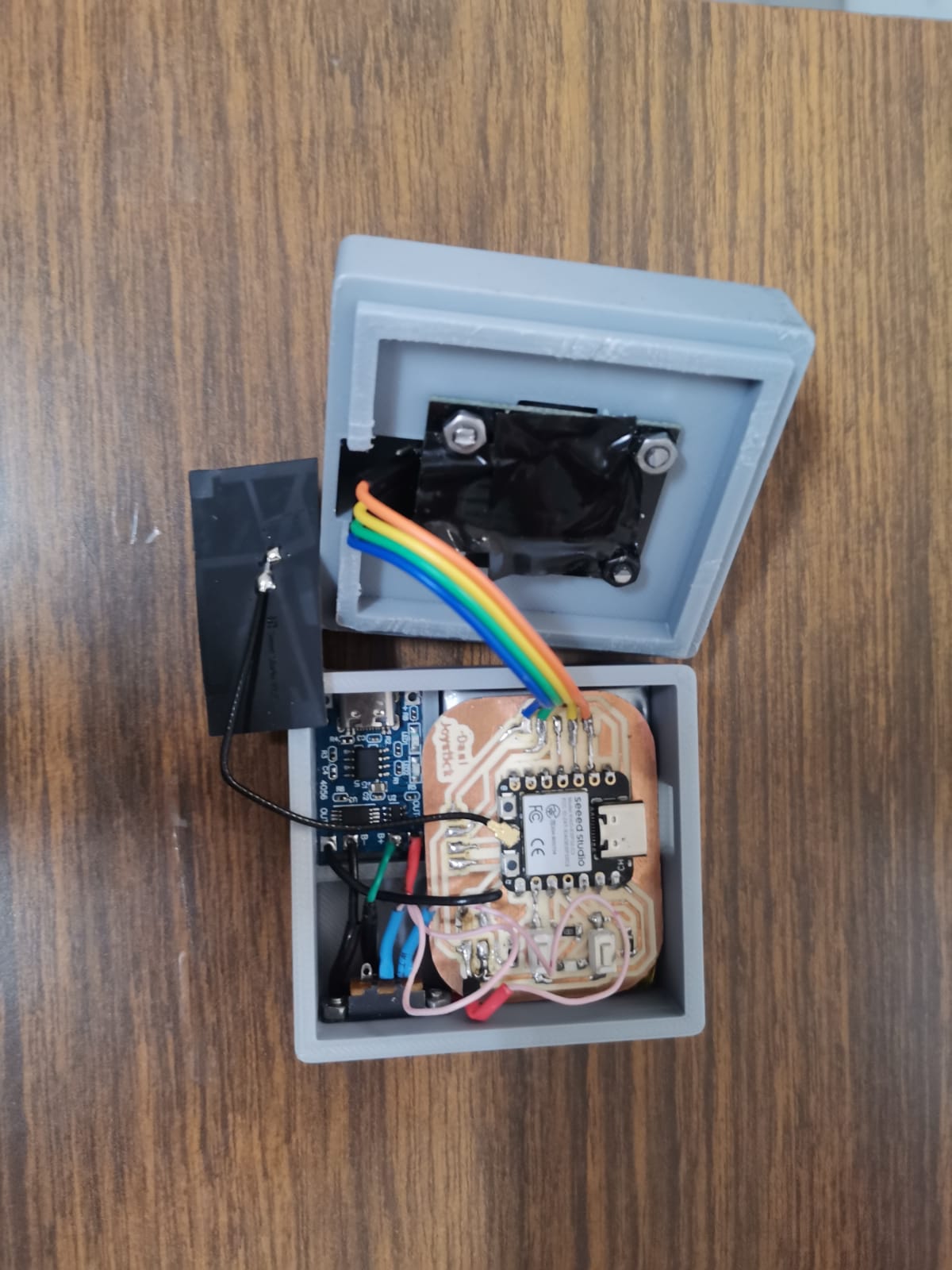
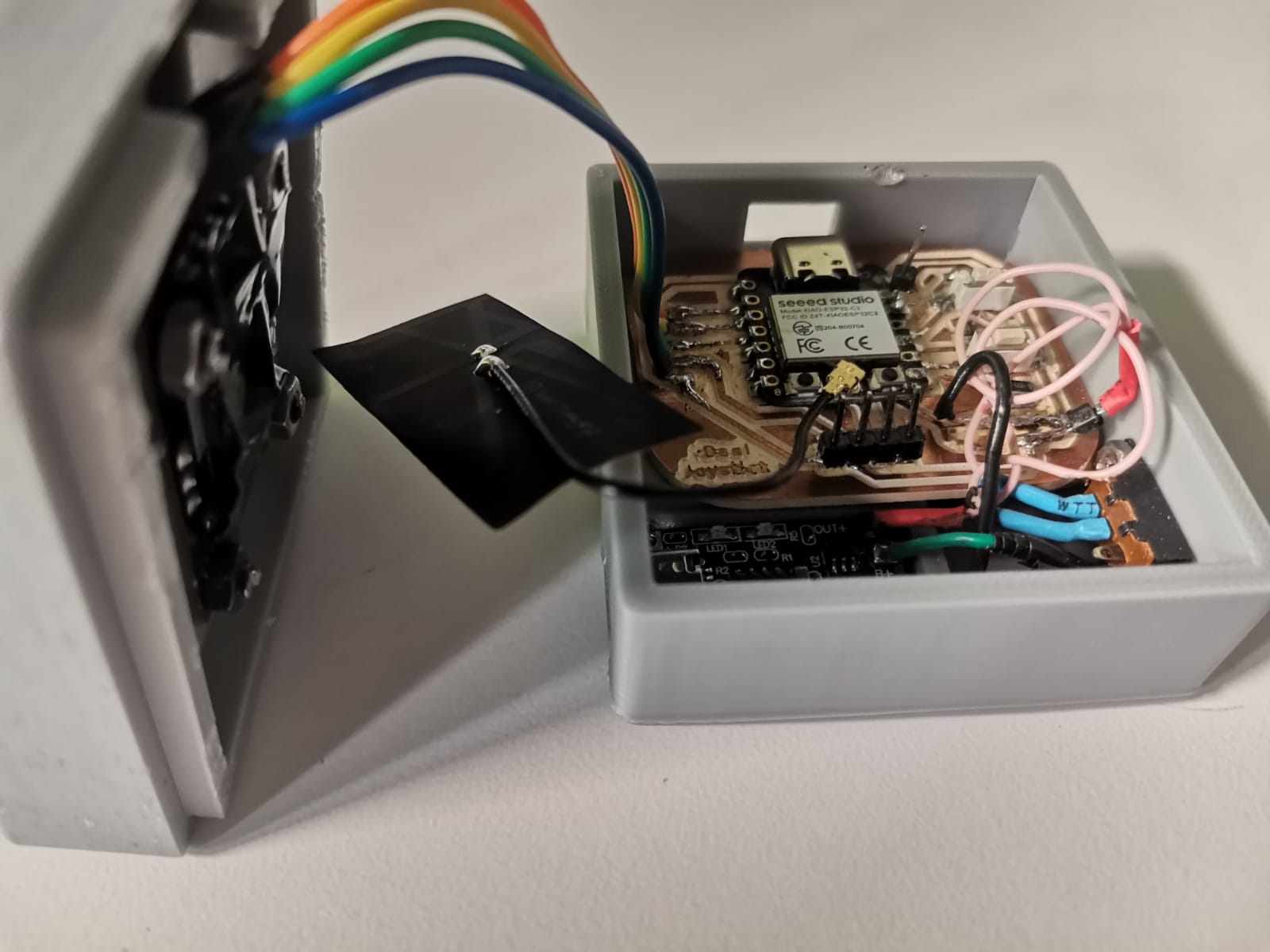
The joystick on the inside looks like this:
And closed:
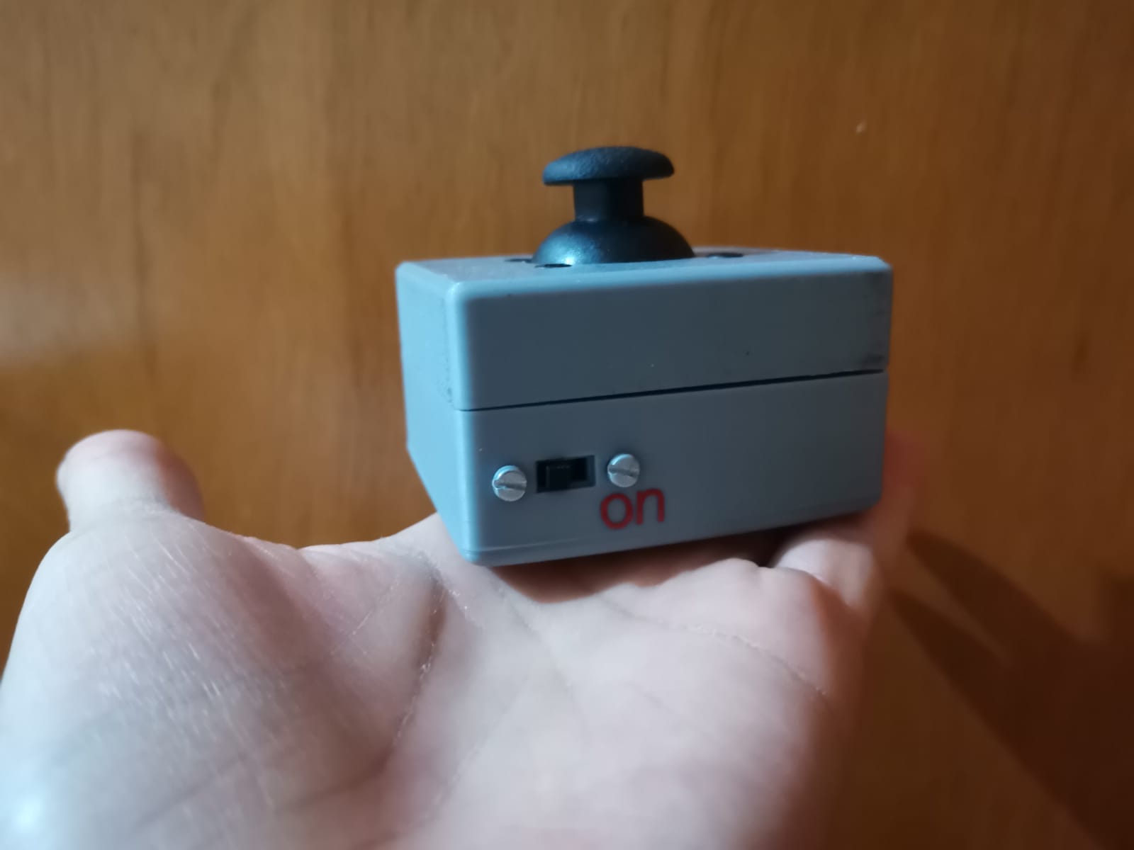
Finally, I only put a sticker in the case to know when is the joystick turned on or off depending on the position of the switch. I exported it to a SVG file and followed the steps from the computer-controlled cutting week.
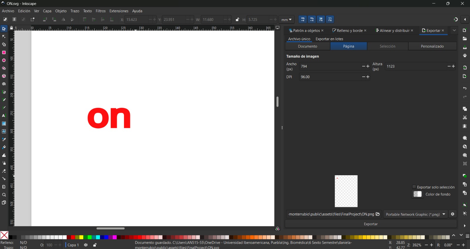
After having the sticker, I pasted it in the joystick case next to the switch in the side where it should be placed to be turned on.
Motorized Part
For the motorized part, the only thing done through the weekly tasks was the motors case in the wildcard week. For that reason, the next things had to be done separately.
Motors Plug
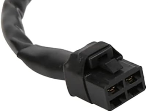
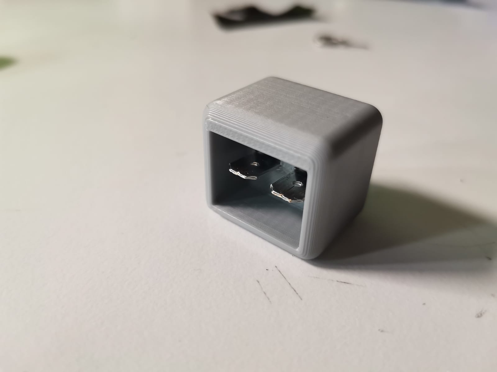
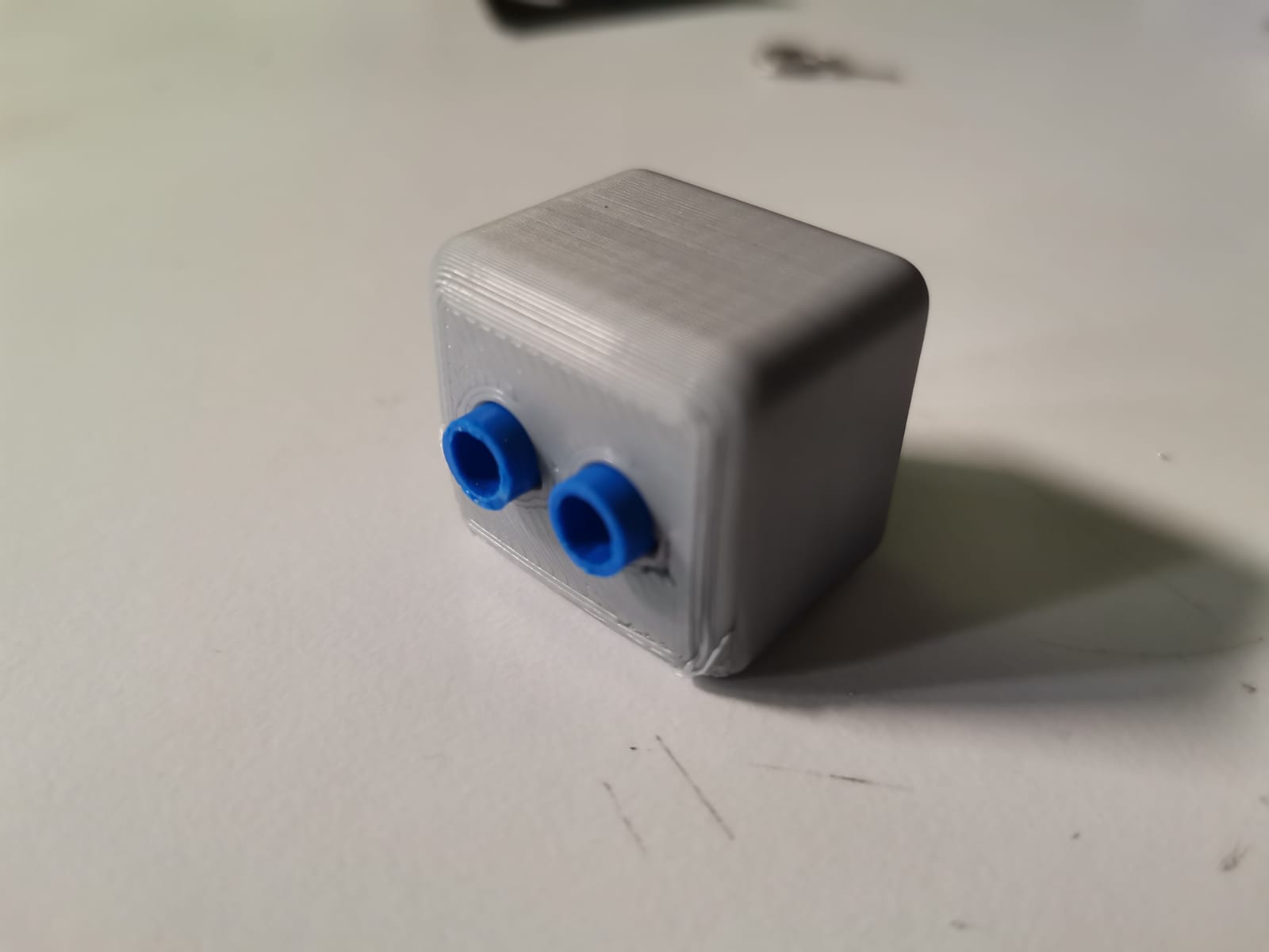
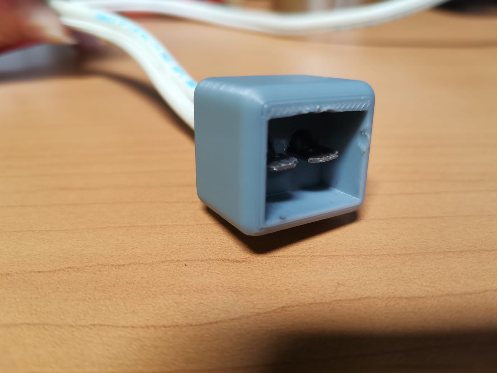
The motors I bought thorugh amazon had a plug I haven't seen in my whole life, so I had to design one for them. The motors' have a female plug with a lock to avoid the male part to disconnect. My design for the plug considered that and made it a little notch to lock the plug.
The design of the plug included a pair of spade connectors (first picture) per motor, as they had a weird shape (second picture). The spade connector fit well in the motor slots.
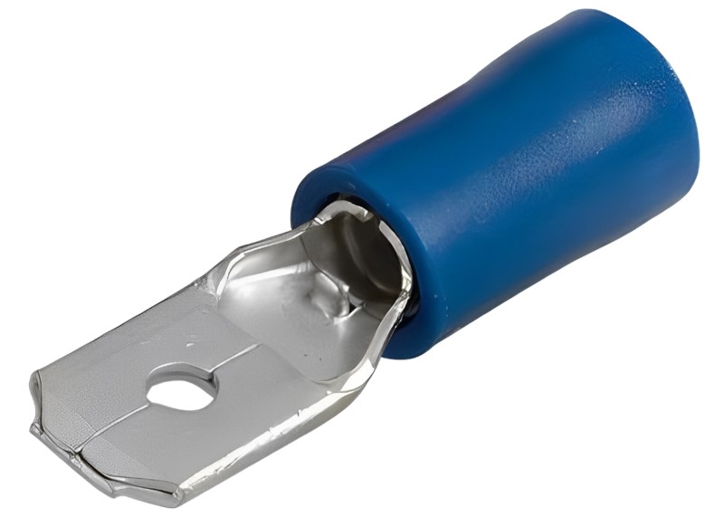
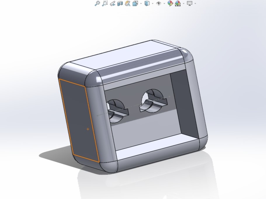
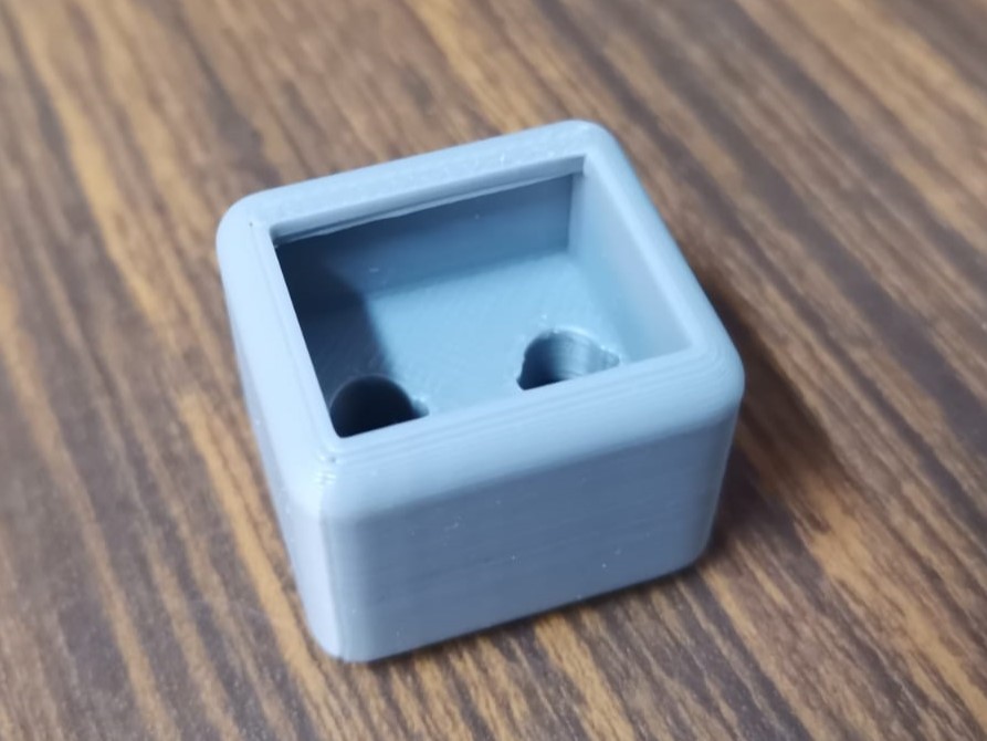
The designing part using Solid Works was fast, because I only needed a piece that would hold the spade connectors in the correct place. I also inlcuded a slot for the motor's lock. As in the joystick, I also used the Bambu printer for this, and after 3 printings I finally came to the final version (third picture). One of the previous versions failied because of the distance between the holes, and the other one because of the space for the lock.
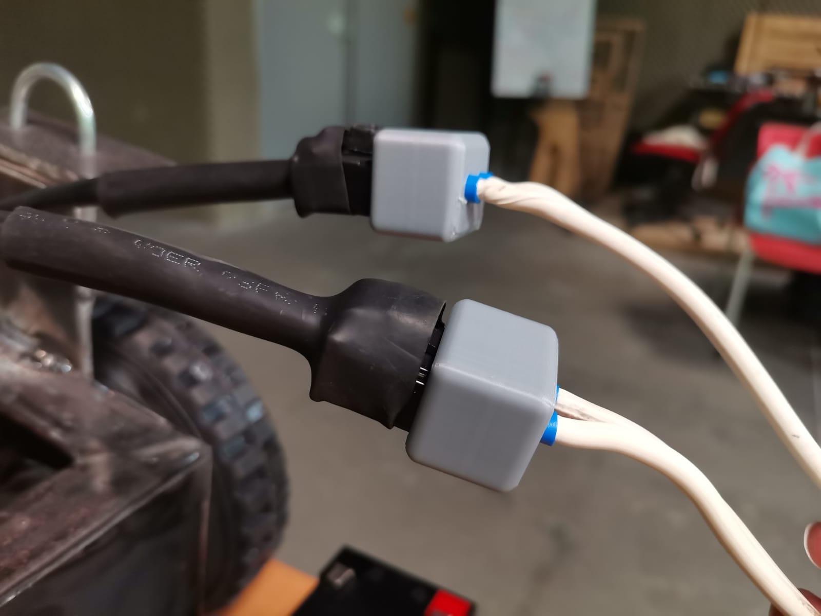
Finally, I placed the spade connectors in the holes and soldered right there the armed cable:
PCB
The specifications of the motors indicated that they need a 24 V supply at 13.4 A, but I also tried them with a 12 V supply and they only went slower. For the design of the motors' PCB, it would require an H bridge that supports the power of the motors. For the circuit I asked a local instructor, so he gave me the following diagram to have a basis for the control of each motor:
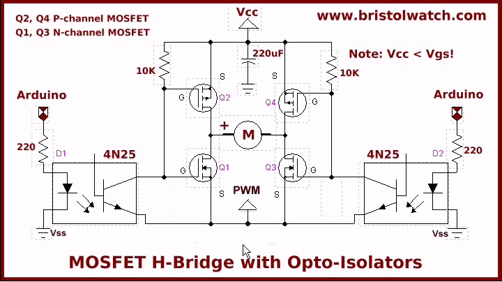
Retrieved from: https://www.bristolwatch.com/ele2/img/a2.jpg
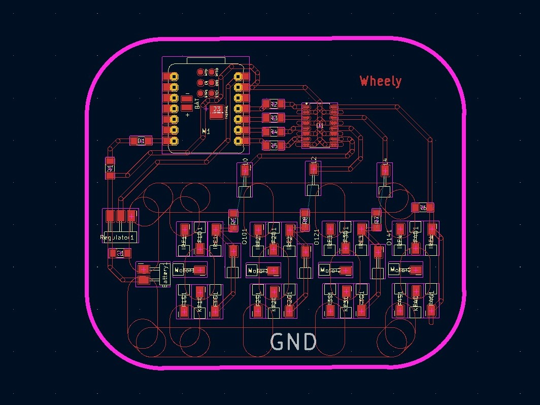
I began doing the circuit directly in a PCB, but it didn't go as planned. A local instructor helped me to calculate the width of the traces in a width trace calculator. This gave a width trace of 7mm for the 24 V motors at 13.4 A (just in case I powered them with that). Then I was also adviced by a local instructor to use an optoisolator to avoid the current to flow into the microcontroller and designed the PCB with that in mind:
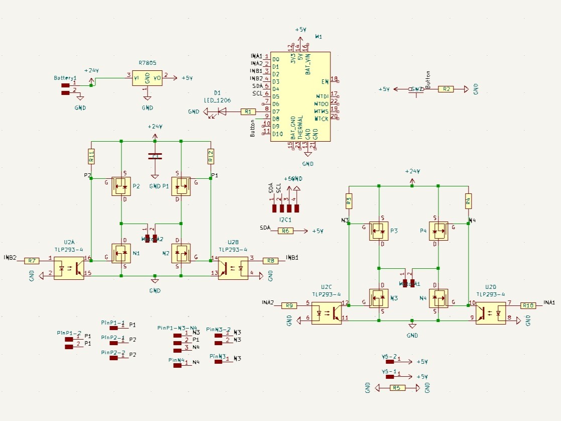
Schematic of the board
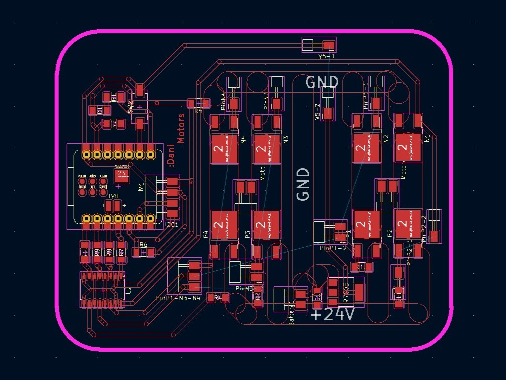
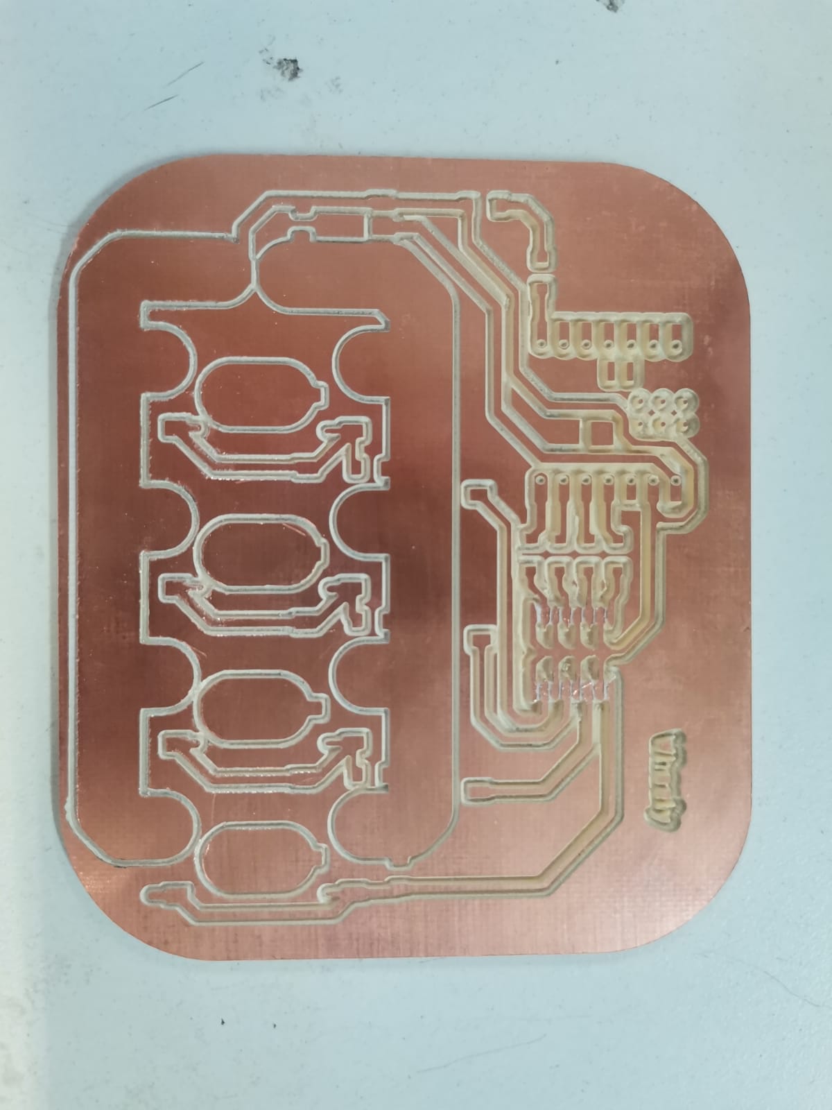
PCB design in the editor
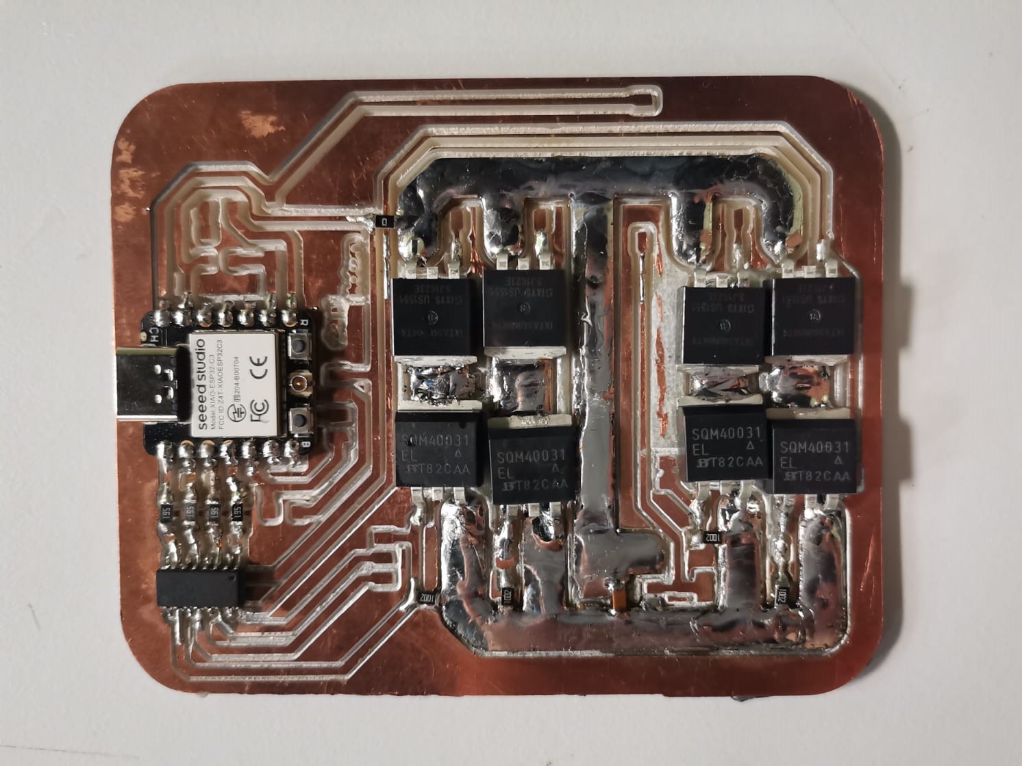
PCB already cut and soldered with tin in the 24 V traces (I didn't achieve the 7mm traces)
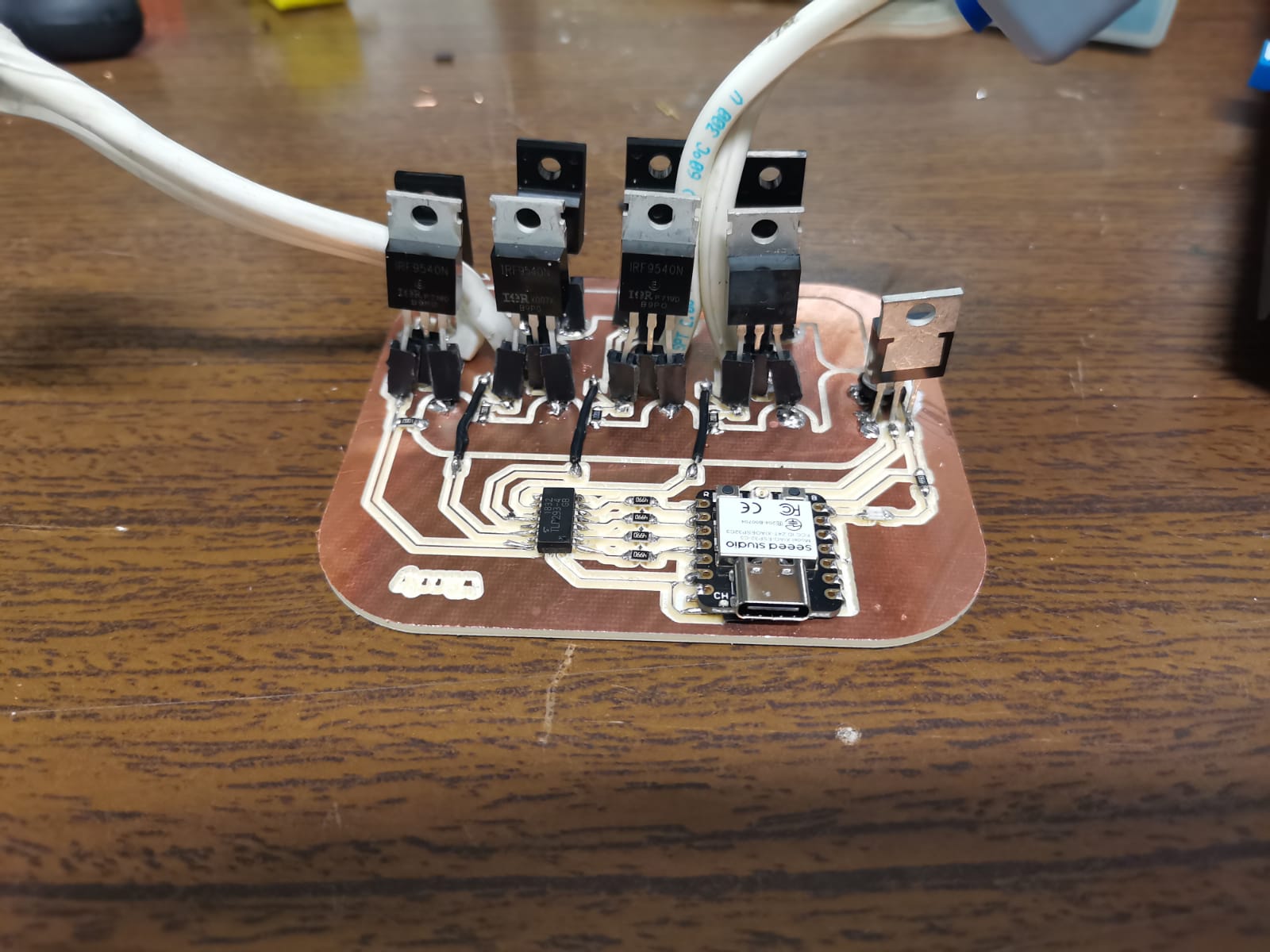
The electronic components for this PCB are:
- 1 Xiao ESP32-C3
- 1 optoisolator
- 4 smd resistors (19 MΩ)
- 4 smd resistors (10 kΩ)
- 1 smd zero resistor
- 1 capacitor (220 uF)
- 4 transistors (SQM40031)
- 4 transistors (IXTA340N04T4)
- 1 regulator LM1117T
- Breadboard cable
I used some protoboard cable to connect some of the signals from the optoisolator to the transistors. I wasn't able to use a zero resistor due to the width of the traces, as there is no zero resistor that long. Then soldered the motors' plugs, as well as the voltage and ground connectors for the battery:
This PCB didn't work and I am still not quite sure why. The theory I had with the two local instructors I spoke to was that there was a short circuit, very probably something caused by me. We thought it as a short circuit, because there were some sparks once I connected the circuit to the power and then everything was burnt (not in a chaotic way, they just had continuity where they weren't supposed to have, but there were no flames or something apart from the little sparks).
After that, I worked on the protoboard following the same scheme given by the local instructor, connecting the Xiao to the optoisolator from the same board (I desoldered everything from that board and left only the optoisolator) and connecting the signals from the optoisolator to the transistors.
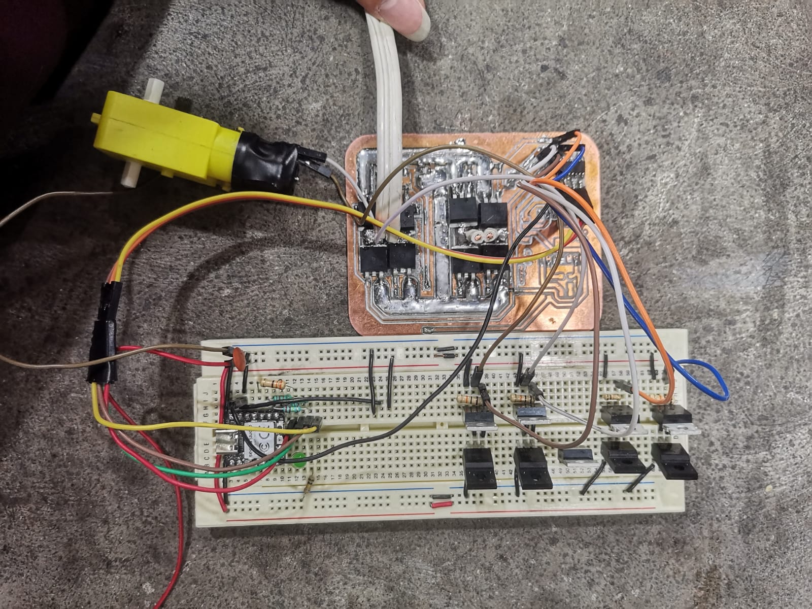
This time, I had to change the transistors as there weren't more of the previous ones that I used. The components now were:
- 1 Xiao ESP32-C3
- 1 optoisolator
- 4 resistors (12 kΩ)
- 4 resistors (10 kΩ)
- 1 ceramic capacitor (220 nF)
- 4 transistors (IRLZ44N)
- 4 transistors (KF20N60)
- 1 breadboard
- Breadboard cable
And it worked, actually:
Then I had to put that circuit in a PCB, which was easier knowing that it works and having the components physically. In theory, this circuit was the same as the first one, but I like this one more:
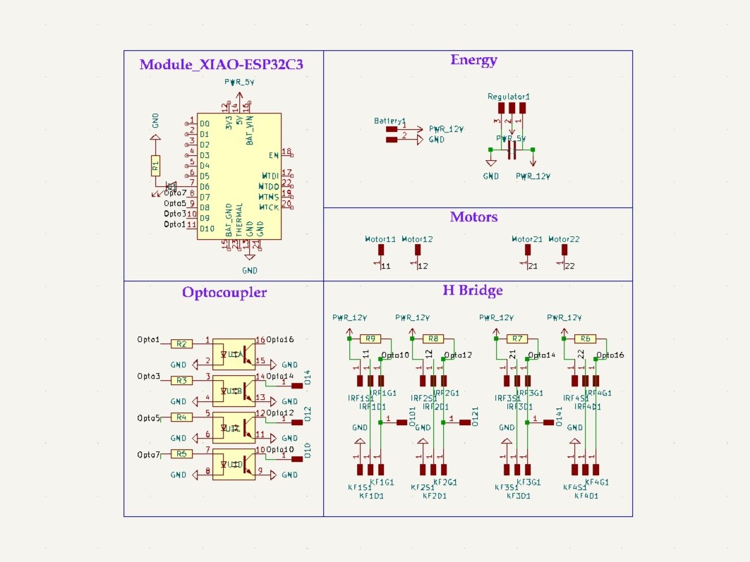
Schematic of the board
PCB design in the editor
PCB already cut
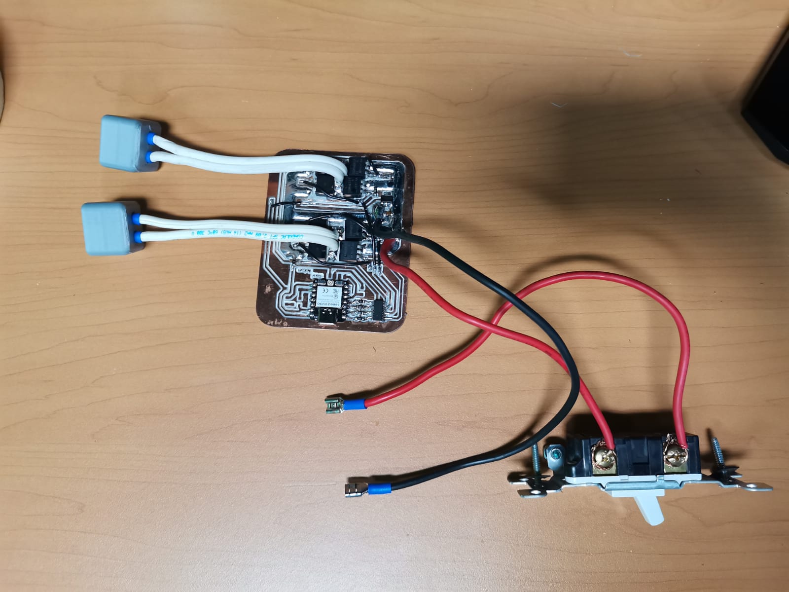
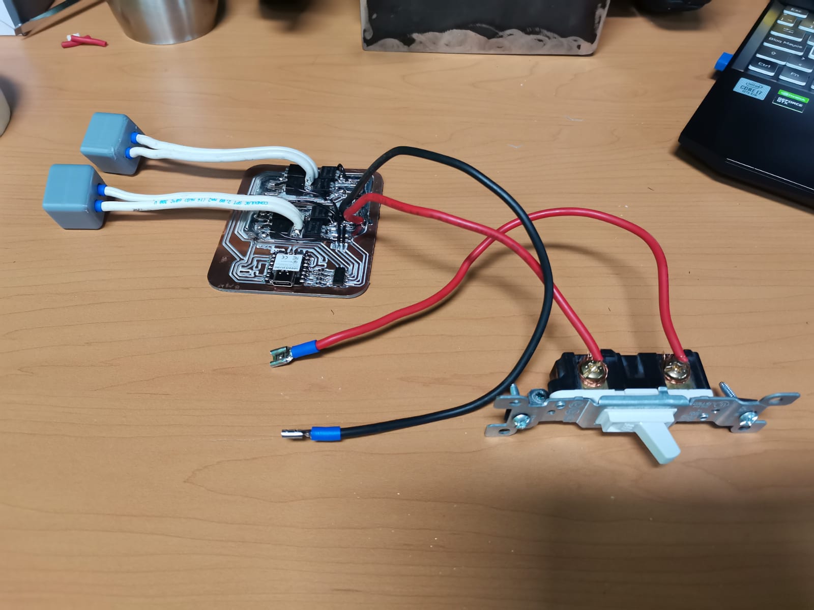
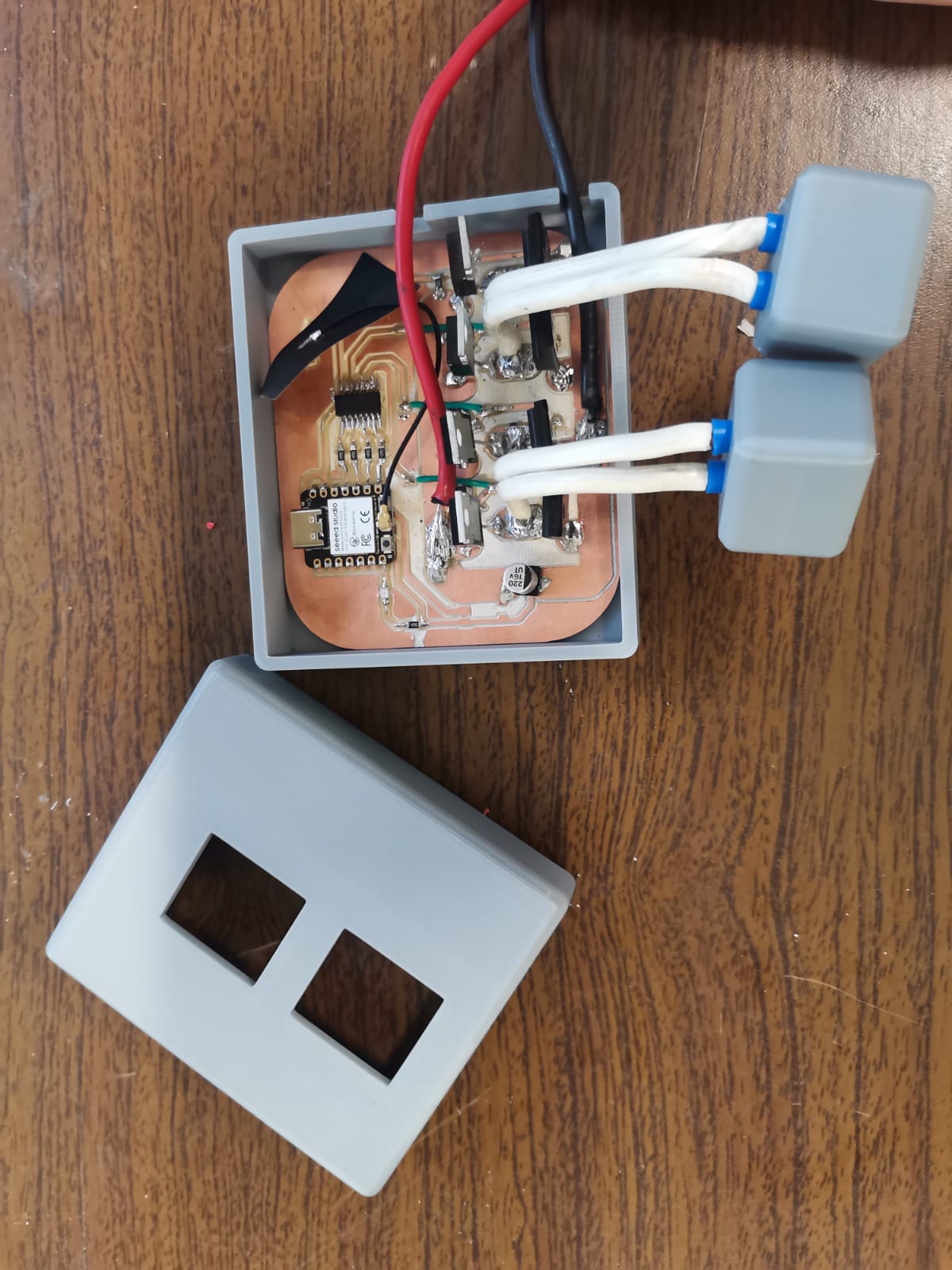
In this case, I used exactly the same components as in the breadboard test (only changed the resistors for smd) and soldered them to the PCB:
Front view of the PCB
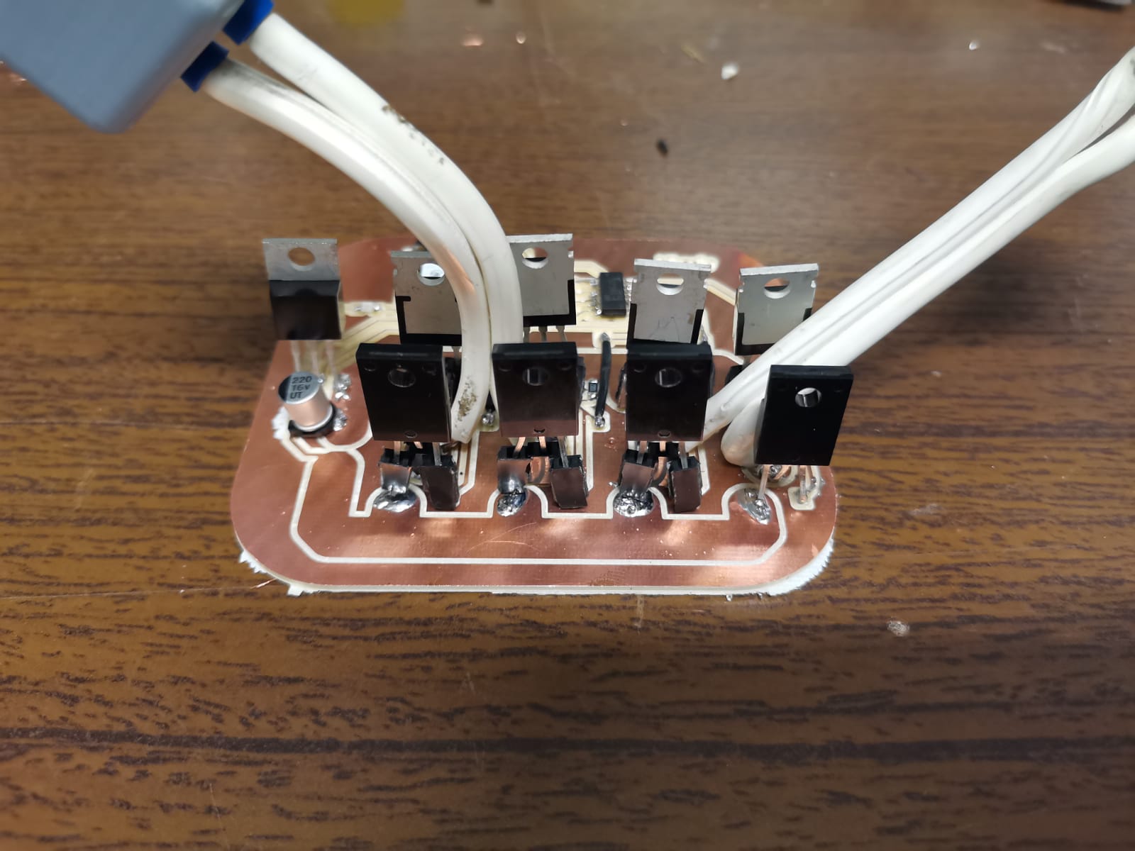
Back view of the PCB
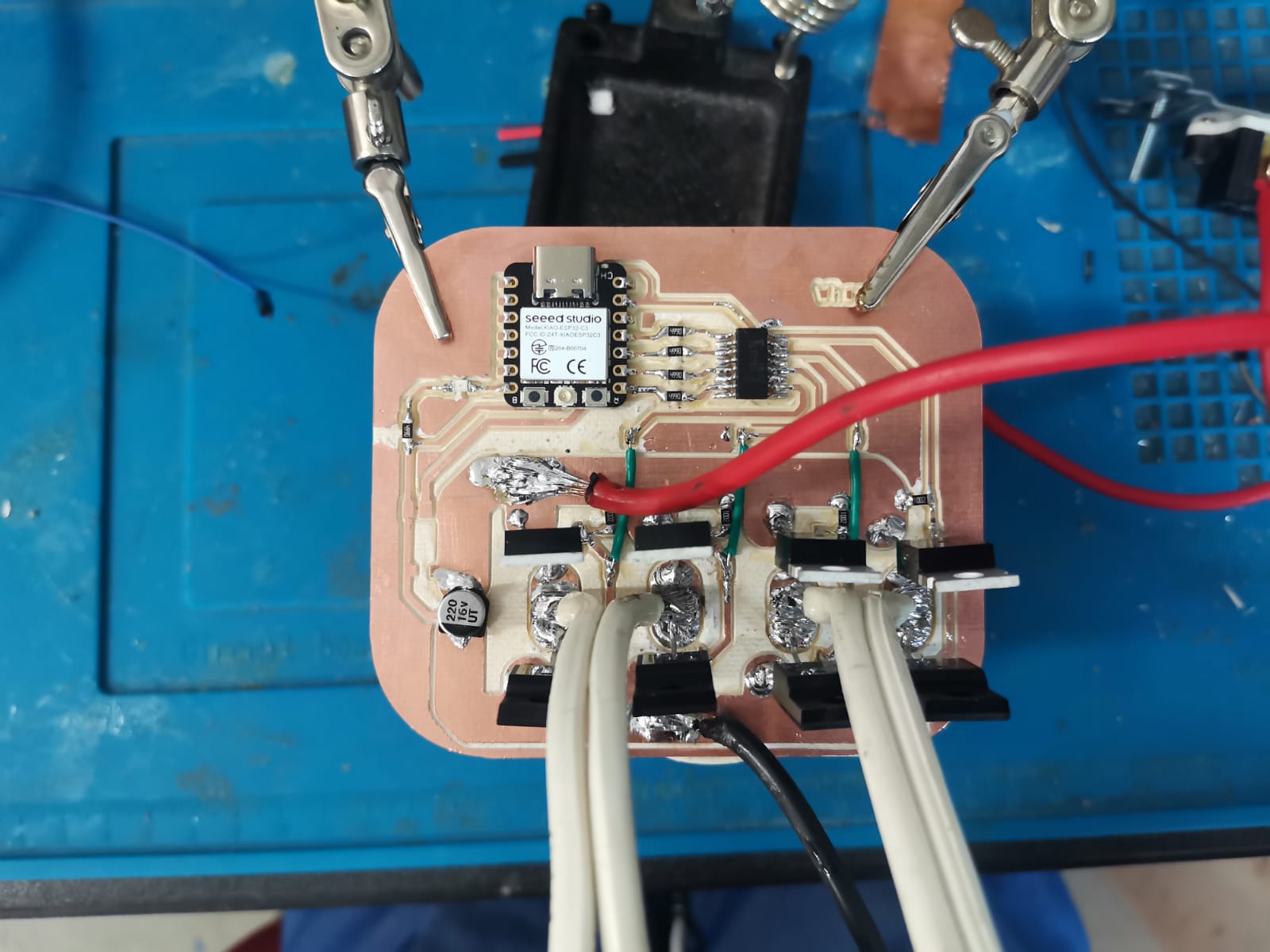
PCB with battery cables soldered
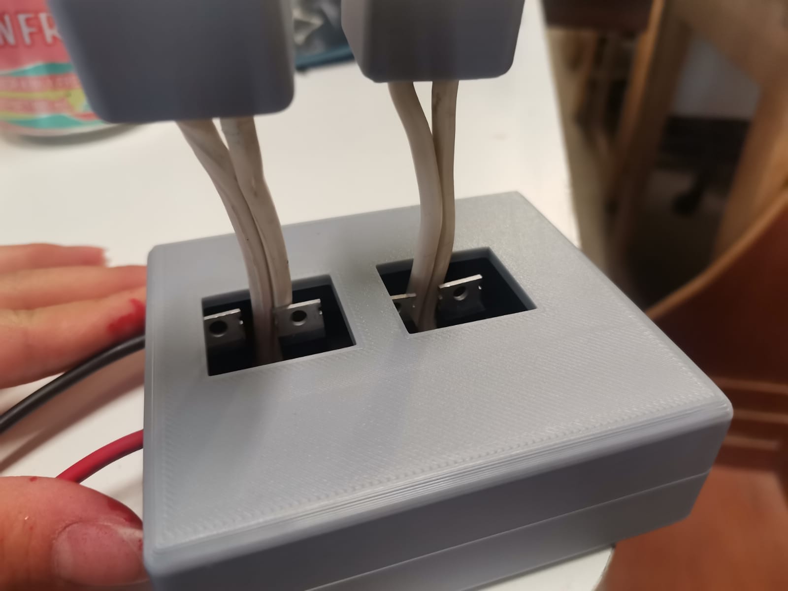
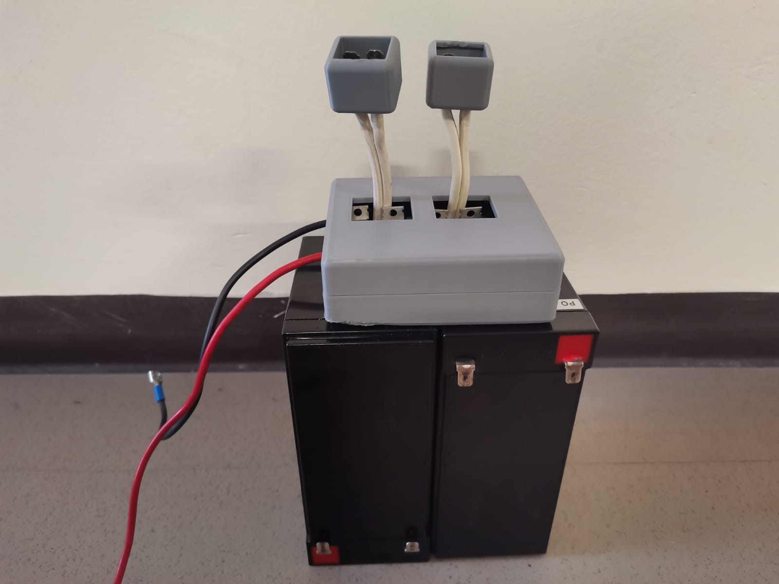
PCB Case
Given that the motors case was made out of metal, I needed a case for the PCB to avoid any type of accident. This case was easier since the battery didn't need to be inside the case, so I just made fast measurements about where I wanted the cables to go out from the case. The final version of the case is the following:
Then I placed the PCB inside it:
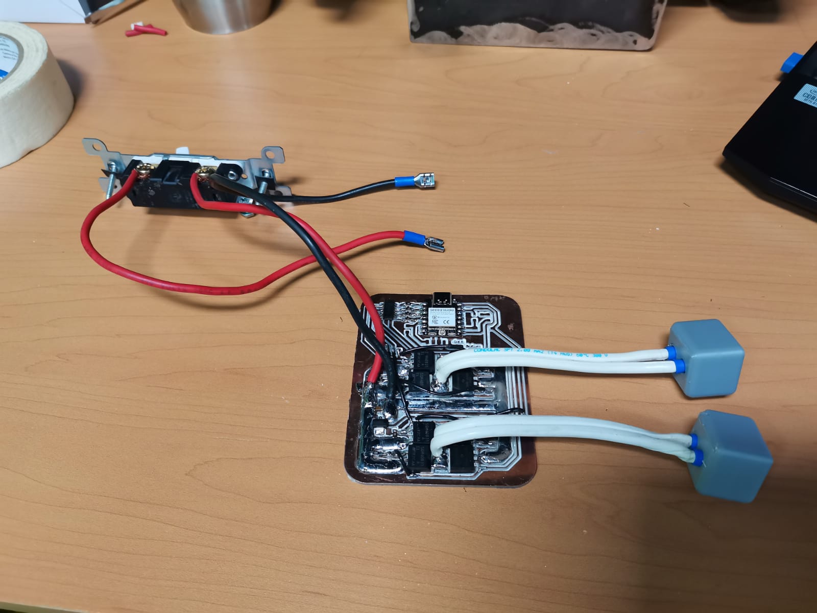
Tests
After having the PCBs and their respectively cases, I placed everything inside the motors case to test them (in the final video, it is possible to see how is the installation of the motors case to the wheel chair). Having done that, the next step was to make small changes to the original client code (.ino) from week 13 to get the final client code, while I used the same one for the joystick as in inputs week:
Server
Client
Then I placced the everything inside the motors' case (battery and circuit), secured the case to the wheelchair, and it was ready to be used.
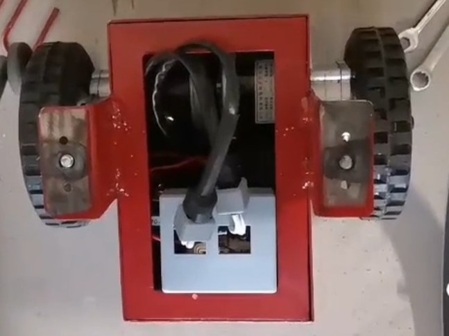
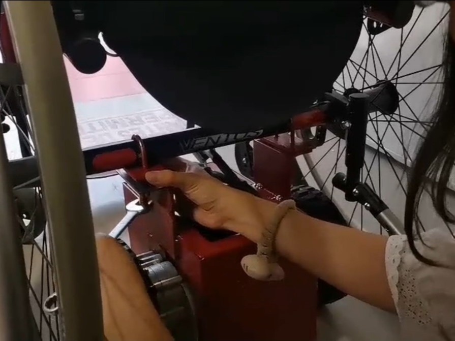

After uploading the code to the motors' Xiao, the final result went this way:
Files
Joytick files
- Joystick case base (.SLDPRT)
- Joystick case base (.STL)
- Joystick case base (.3mf)
- Joystick case lid (.SLDPRT)
- Joystick case lid (.STL)
- Joystick case lid (.3mf)
- ON Sticker (.svg)
- Joystick code (.ino)