3. Computer-controlled Cutting
This week we had several tasks, one as a group assignment and two individual assignments. The group assignment consists of characterizing the lasercutter. The first individual assignment is to create a parametric construction kit with the lasercutter. The second individual assignment to cut something on the vinyl cutter.
Characterization of the Lasercutter
The characterization was a group assignment, therefore FabLab Puebla created a page for the group assignment. We also had individual lessons to learn about how to manipulate the lasercutter.
Steps to use it
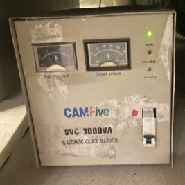
- Turn on the machine's fan (lower left side).
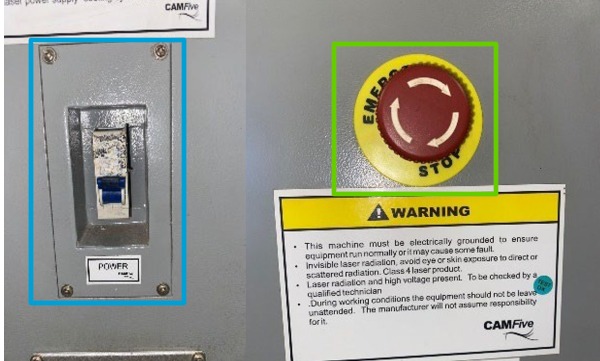
- Turn on the machine (blue rectangle) and deactivate safety stop (green rectangle).
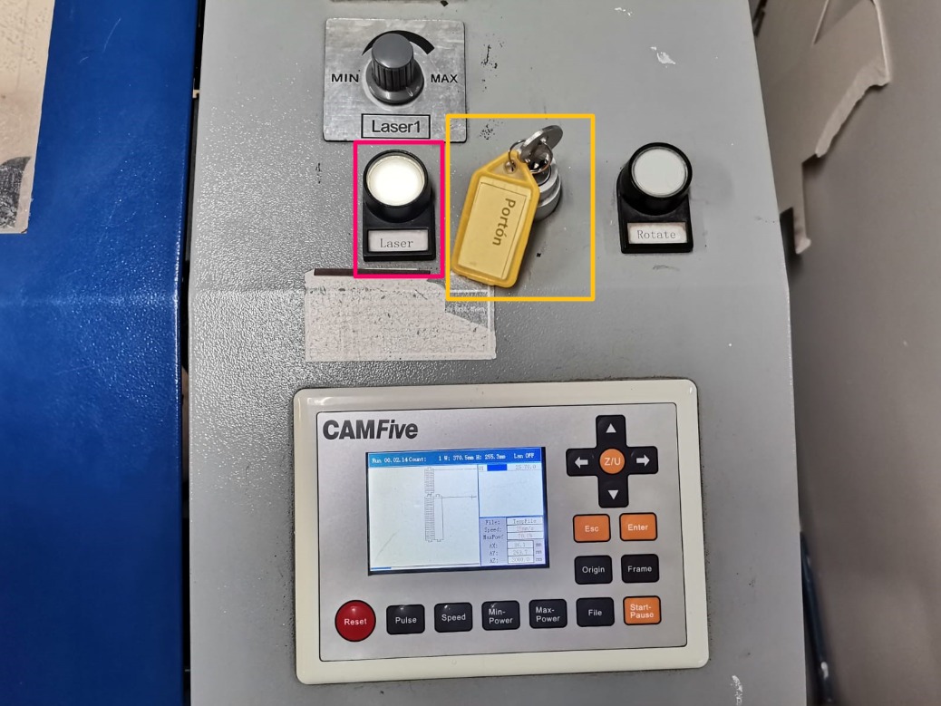
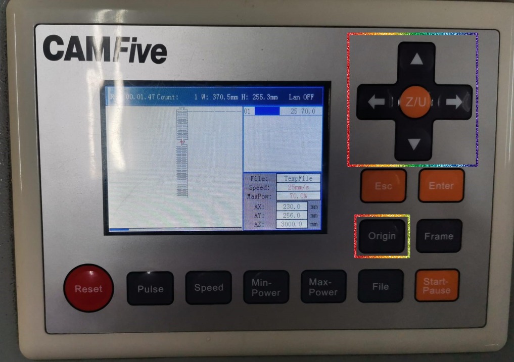
- Unlock the machine with the key on top right of the machine (pink rectangle) and press the button to turn on the machine (yellow rectangle).
- Place the material on the worktable (making sure that it fits the dimensions).
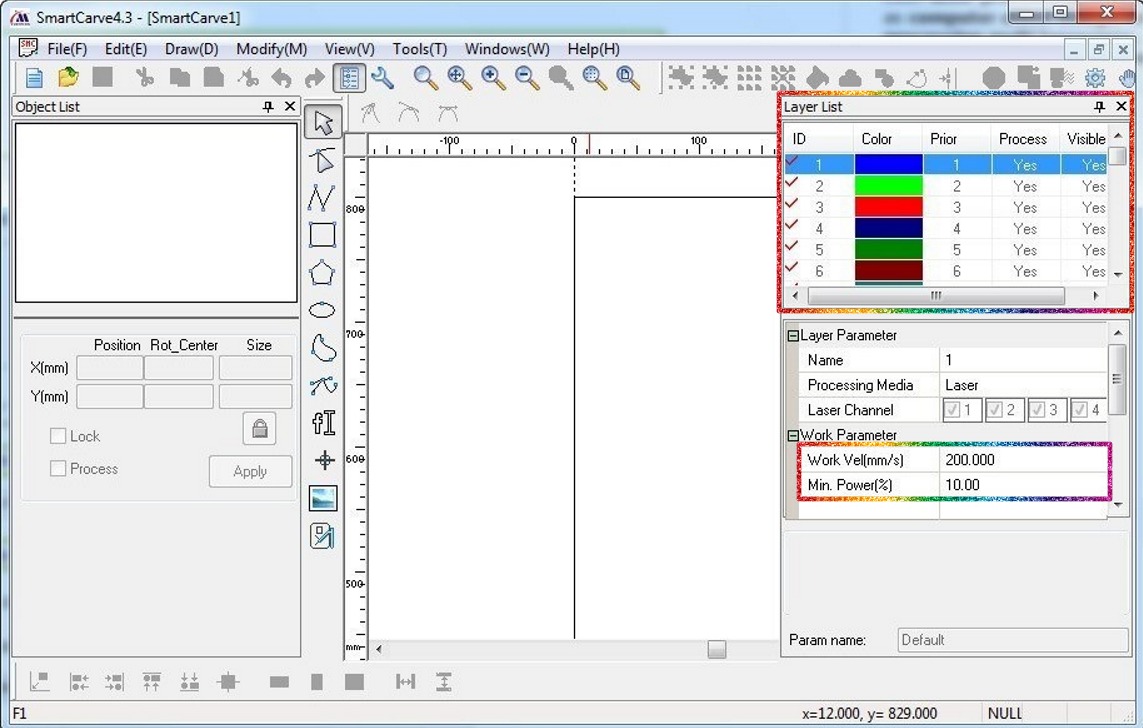
- Open "Smart Carve" on the computer.
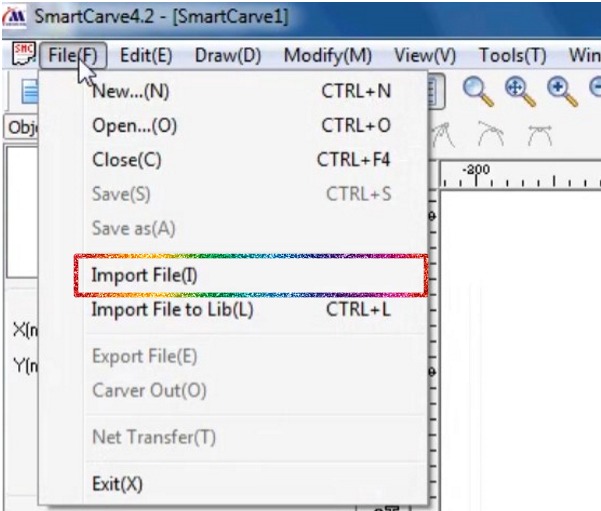
- Import the desired drawing.
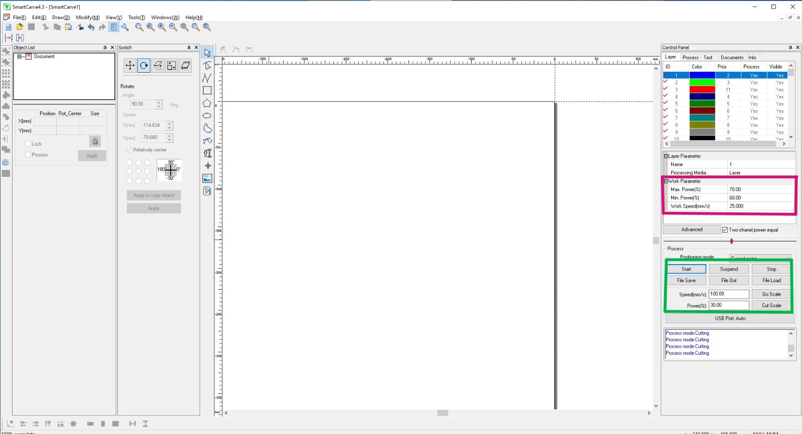
- Adjust the specifications (cutting speed and laser power) and order of the layers (1. engraving, 2. innternal cuts, 3. external cuts). Then apply the modifications (double-click the checkmark next to the configuration number).
- Set the origin (arrow controls) and the distance between the laser and the material (press Z/U, then "Z move" and adjust it to 5 mm).
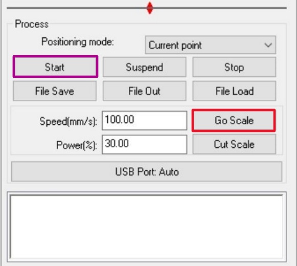
- Verify that the size of the material satisfies all the material needed with the "Go scale" button (red rectangle) and press "Start" to begin the process (purple rectangle).
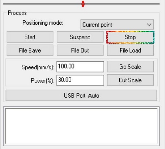
- When the process is complete, stop the lasercutter from the software ("Stop") and wait for it to completely stop.
Characterization
There were several tests to know the results of each power and speed, that are documented in the group page, as well as the test to determine the kerf of each cut. Finally, we were also given a set of joints from which we could choose to use in the kit. From all this I have the characteristics and joints that I used in the creation of the construction kit:
- Clean cut:
- Power: 60%.
- Speed: 40 mm/s.
- Engrave:
- Power: 30%.
- Speed: 50 mm/s.
- Kerf: 0.123 mm.
- Joint: wedge
Parametric Construction Kit
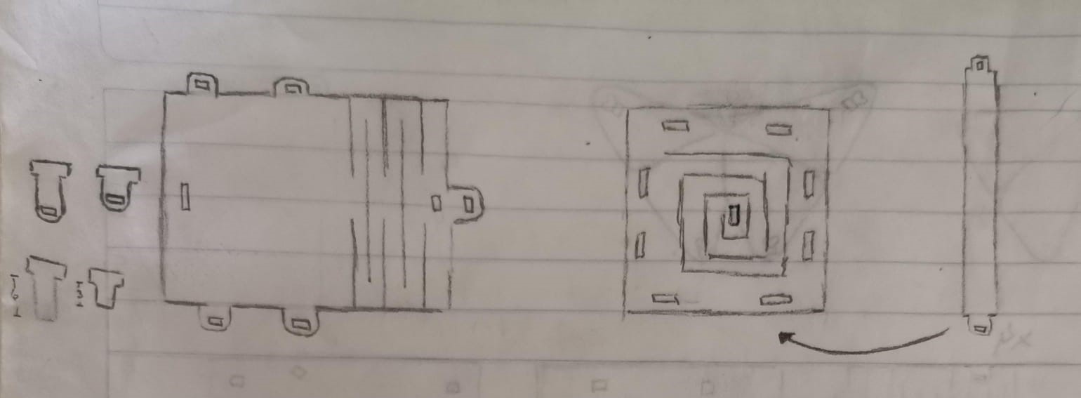
For the parametric kit I had the idea for it to build little houses. In this case I used the wedge joint so that the wedge-shaped piece would be the only one that may vary in length. I drew the following sketch by hand and then with Inkscape, athough I changed a little bit the original idea when drawing with Inkscape:
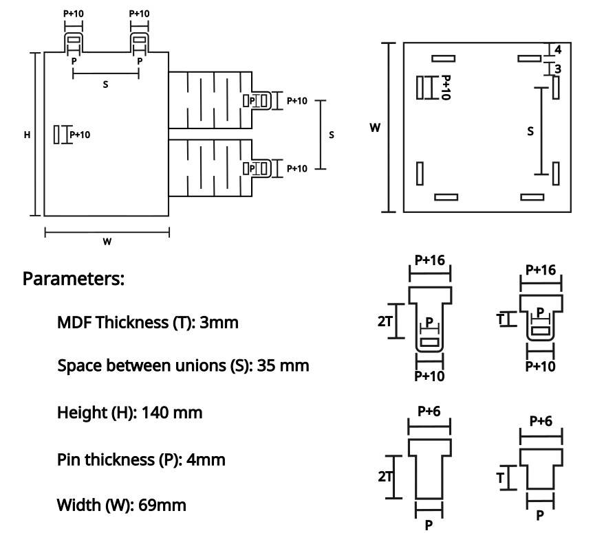
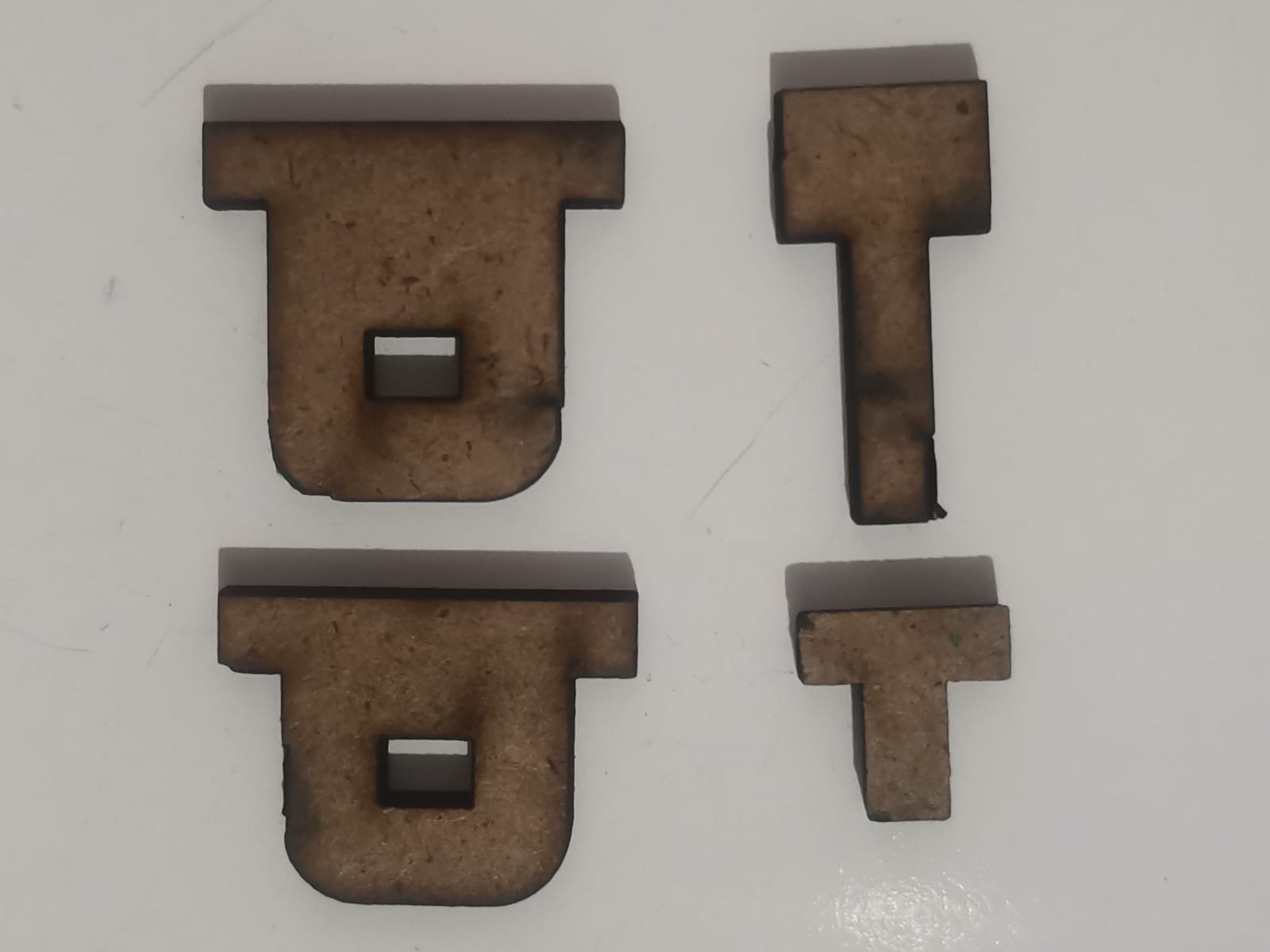
Also, the local instructors gave us some templates (located as well in Puebla's website) of which I used the wedge. I didn't modify any value from this template, because they all fitted well and I liked their size. I took the templates and added the parts needed to draw the complete parts:
And the living hinge, in which I only had to modify the material thickness (T):
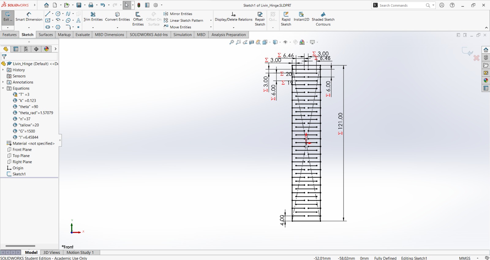
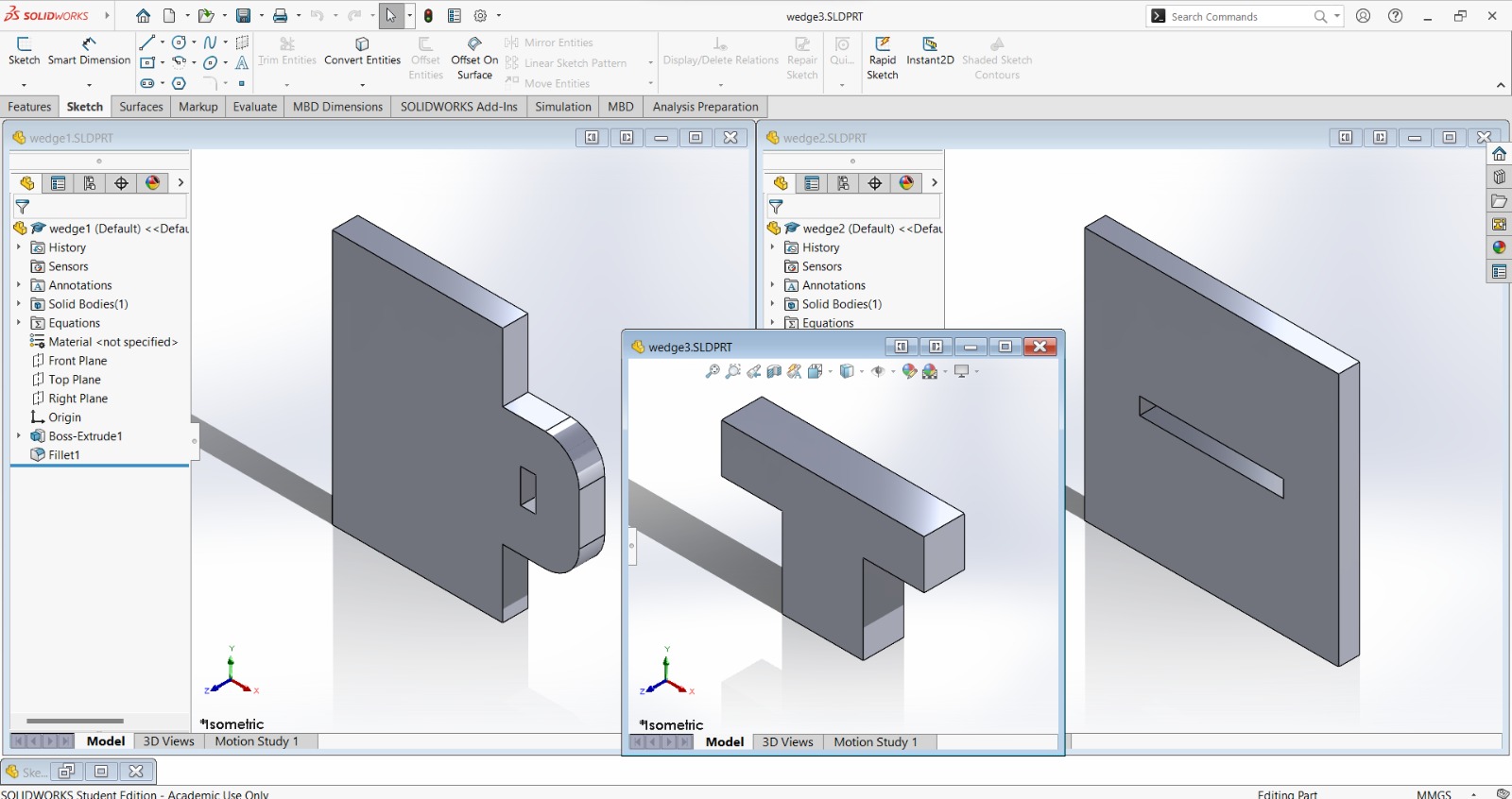
Then I drew all the parts in SolidWorks:
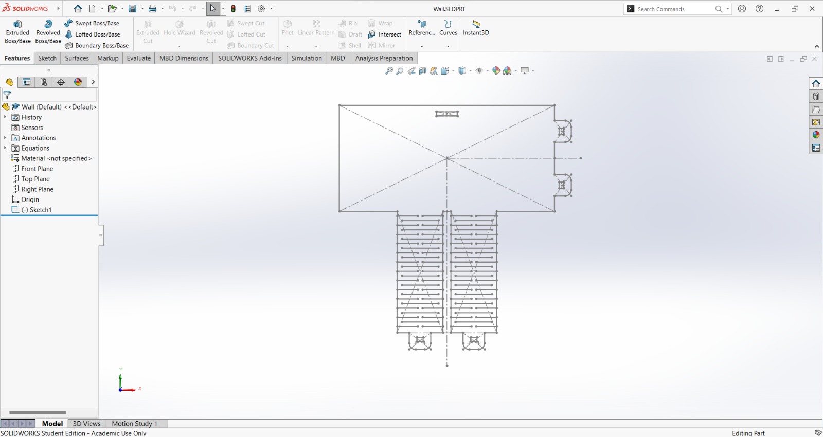
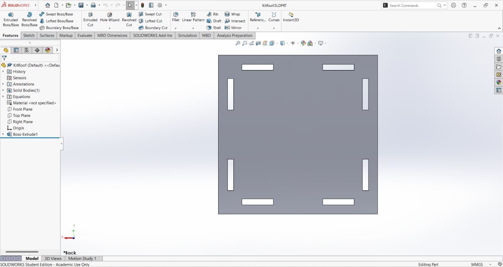
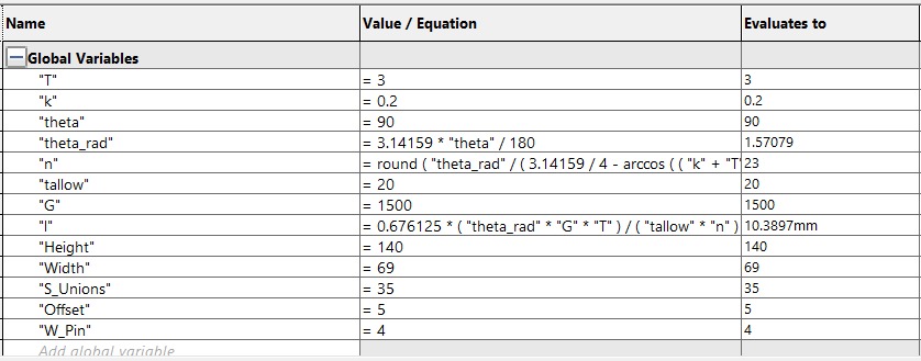
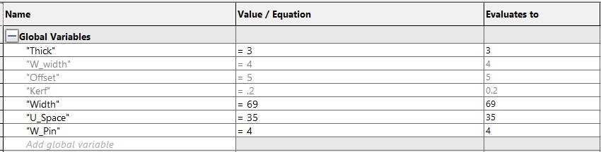
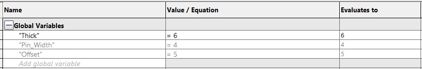
With the following global variables:
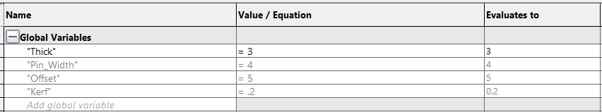
Wall variables:
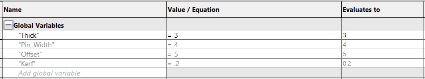
Roof variables:
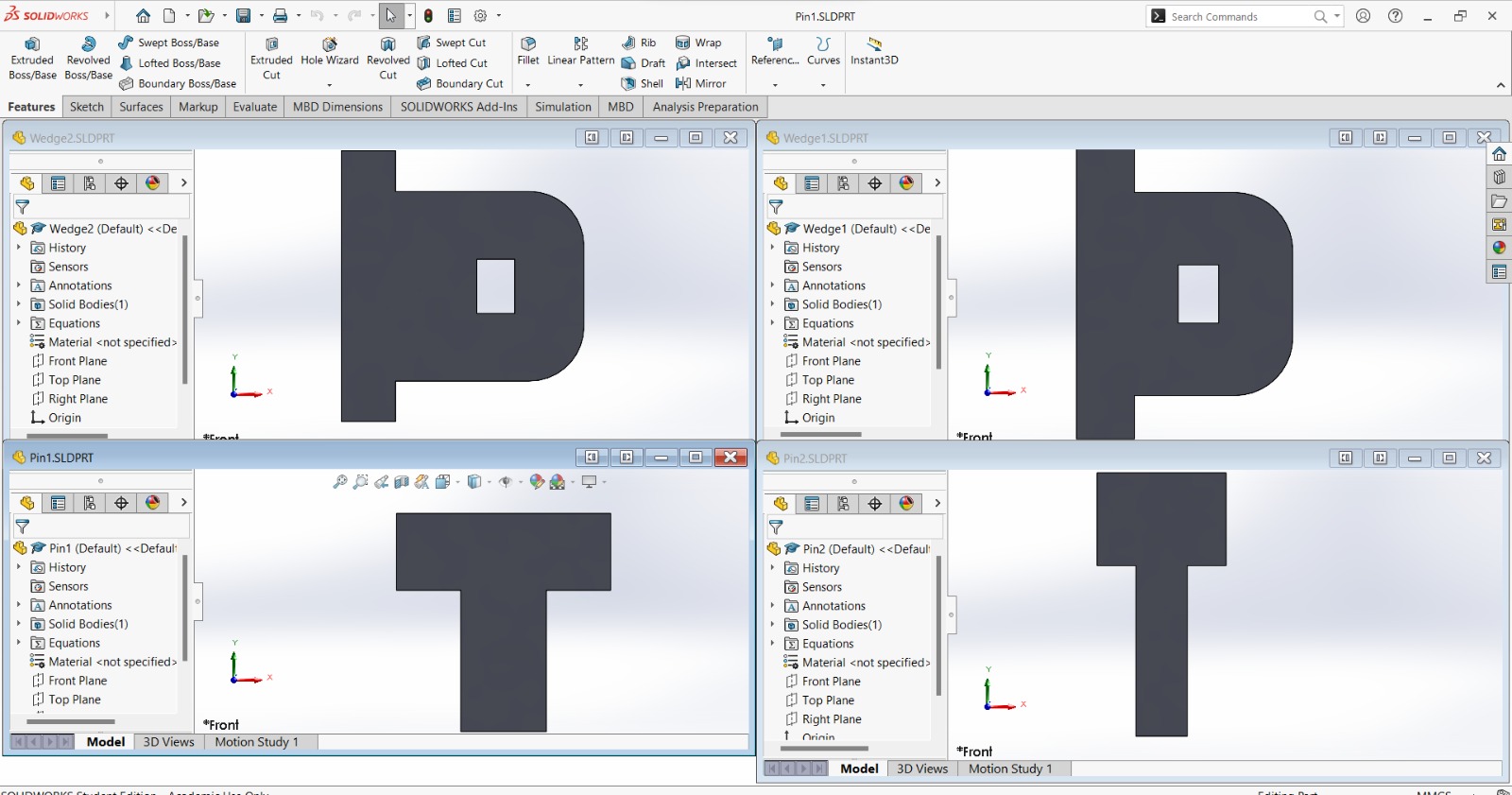
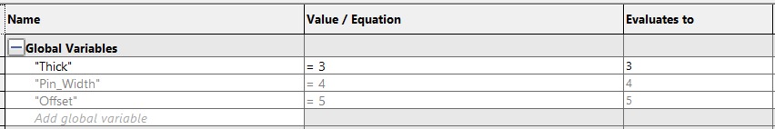
Wedge 1 variables:
Wege 2 variables:
Pin 1 variables:
Pin 2 variables:
The software that controls the laser cutter is SmartCarve, so I imported all the files into the working space (file tab -> import) one by one. Then I adjusted the laser parameters (pink rectangle) according to what I observerved in the group assignment. I also verified that the cutting didn't exceeded the area of the material using the "Go scale" button (green rectangle) and then proceeded to begin the process with the start button (green rectangle).
The laser cutter worked as following (the video is faster than the original):
The results of each part:
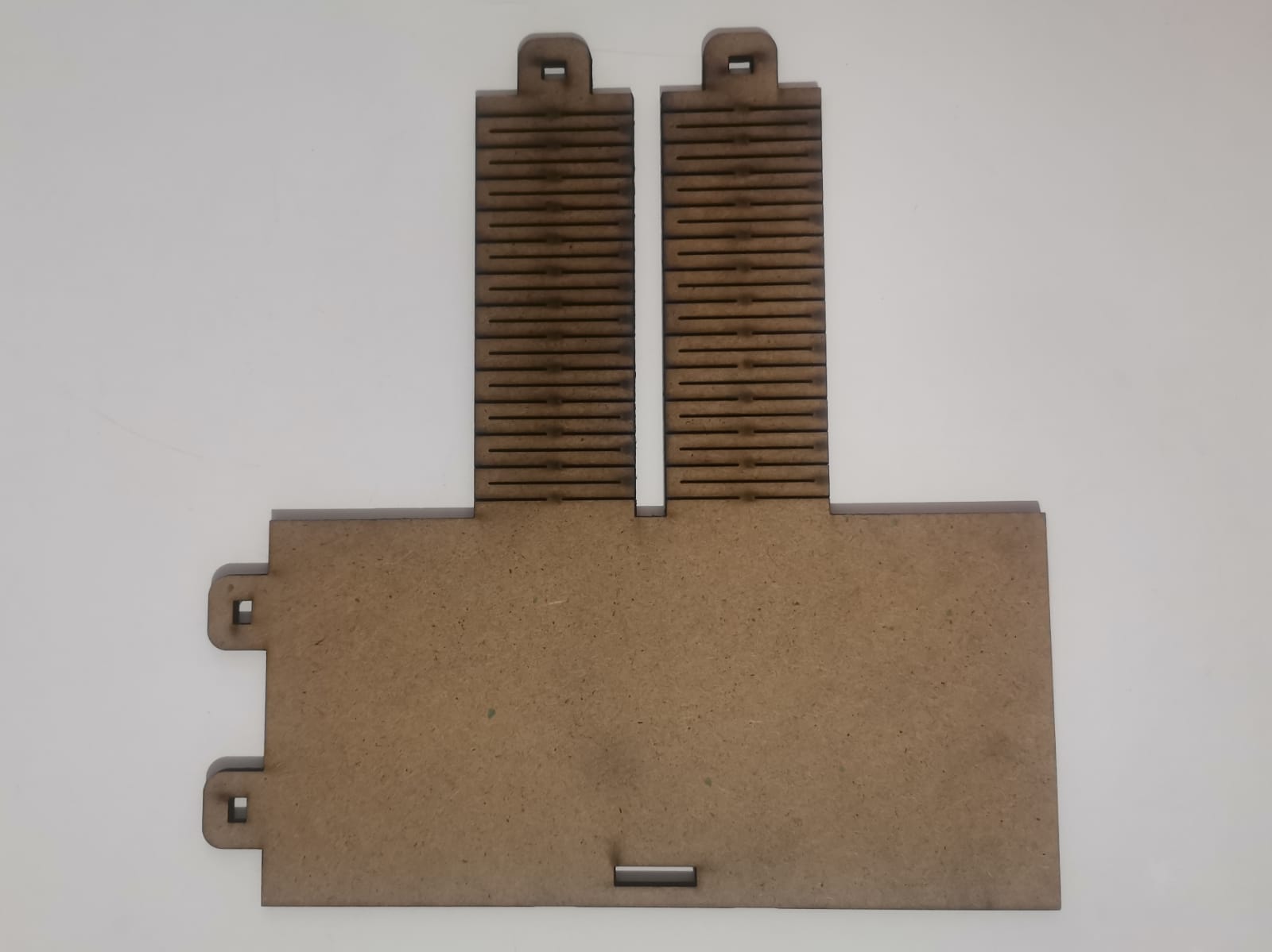
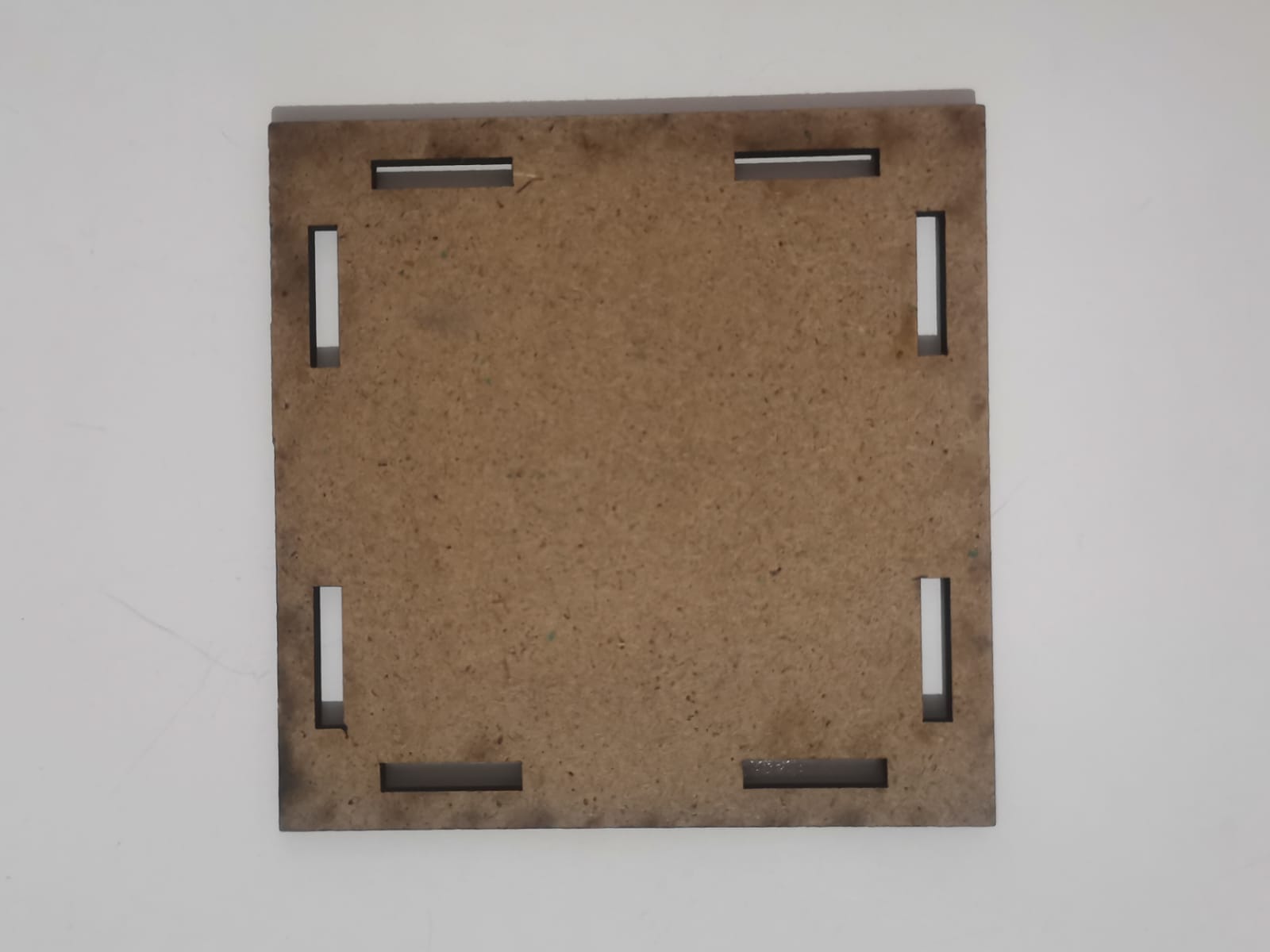
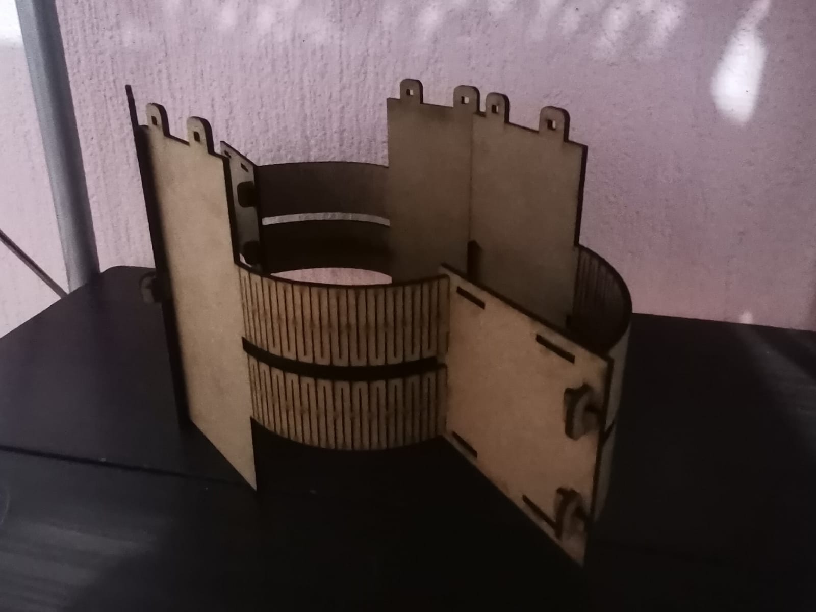
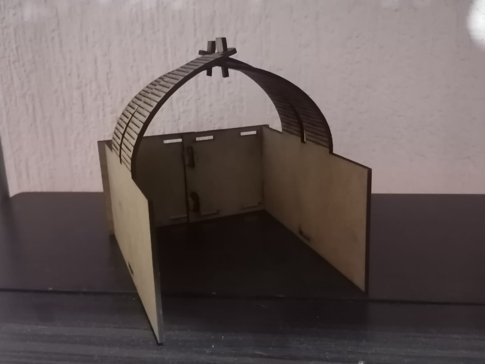
With those pieces I built the following:
Some problems
The main problem I had with the assembly of the kit was that the part didn't fit quite well at first. They moved when I put them with each other:
This was mainly because of the kerf and the real thickness of the material (2.37 mm). The original kerf I used was 0.2 mm, because that's the one I learned from a previous subject, but it didn't fit quite well in this activity because I thought the kerf was something kinda universal for every material and every material width. Once I saw and completely analized the group page, I understood what the kerf really meant, so I applied the group page kerf value of 0.123 mm and all the pieces joined correctly.
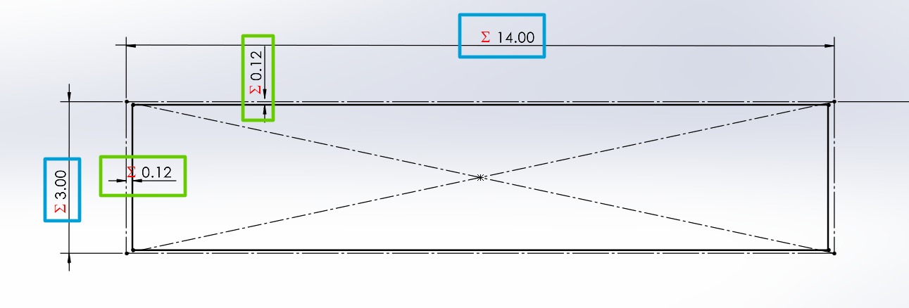
Inside the parameters of the kit pieces I named the kerf as k with the corresponding value. I used this parameter to affect the dimensions of the holes in each part. What I mean with this is that the hole must have a compensation in its dimension in order to perfectly fit with each other. The implementation of the kerf is by considering the amount of material that "dissapears" with each cut of the laser. This compensation in dimensions may be placed in the holes of the pieces or in the parts that are going to fit inside those holes, but I chosed the holes because it was easier for me to think about it. The process consists in havin the original dimensions of the shape (blue rectangles) and substract the kerf from each dimension (green rectangles). The reason for this is that laser beam technically has a width of 0.123 mm, which will "eat" the recpectively amount of material in each cut.
Vinyl Cutter
to cut on vinyl I used the Silhouette Portrait 3, which is a portable vinyl cutter including the cable USB, the power cable, the mat, the autoblade, the blade adjustment tool, and the adaptar. This machine is connected to the computer through the USB cable and controled with the Silhouette Studio software.
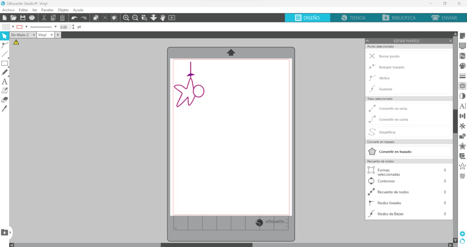
For the vinyl cutter I used last week's drawing:

Then I downloaded the Silhouette Studio software that contorls the vinyl cutter. On Silhouette I pasted the picture in png format.
I secured the vinyl to the plastic plate and connected the vinyl cutter to my laptop through a USB cable to send it.
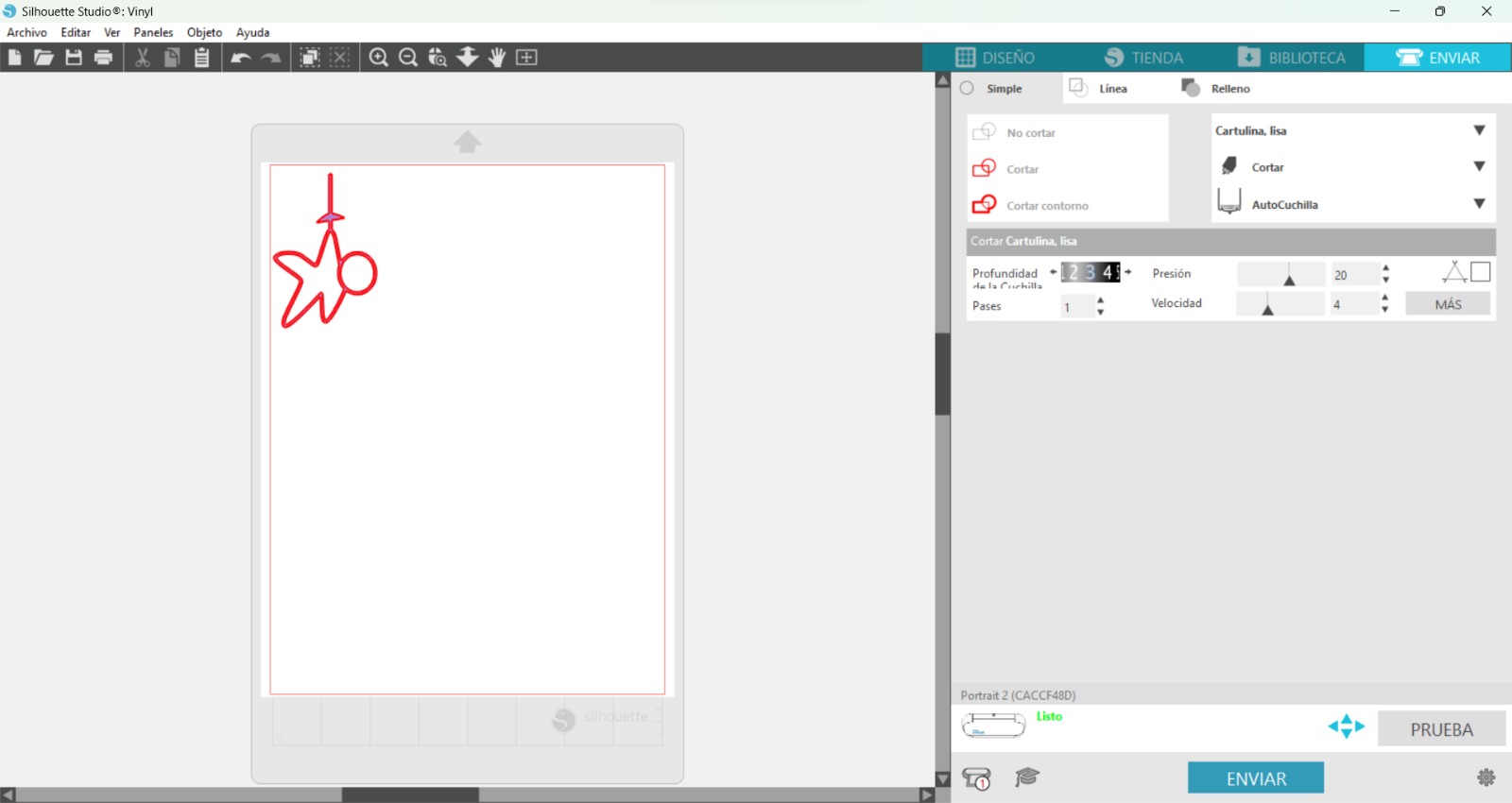
It cutted the picture.
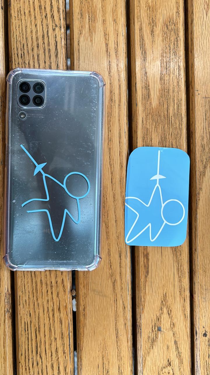
And for the final result I pasted the sticker on my phone: