11. Input Devices
The task of this week is all about input devices, so I used a joystick. The decision to use a joystick for this week's task is because for my final project I'd be using one to control the motors of the wheelchair. Although it seemed simple to implement it, I had some problems using the OLED (which, as an output device, isn't at all from this week). The problems came because I didn't contemplate the use of the OLED and didn't practice with it during the output devices week.
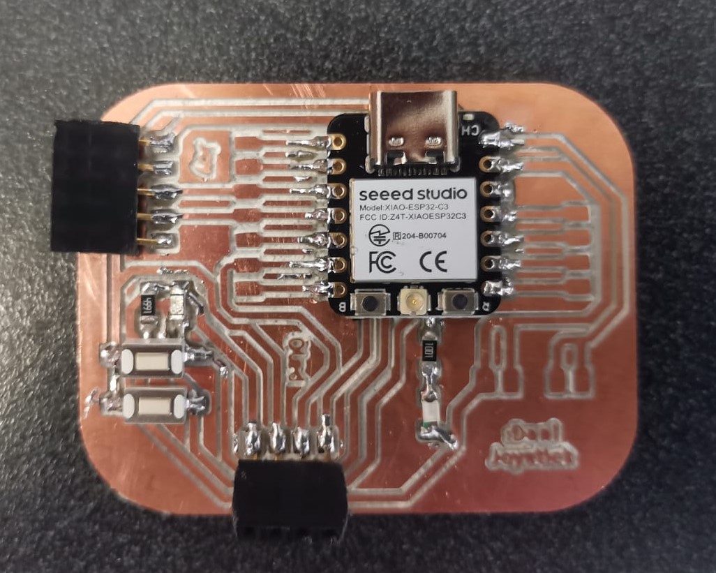
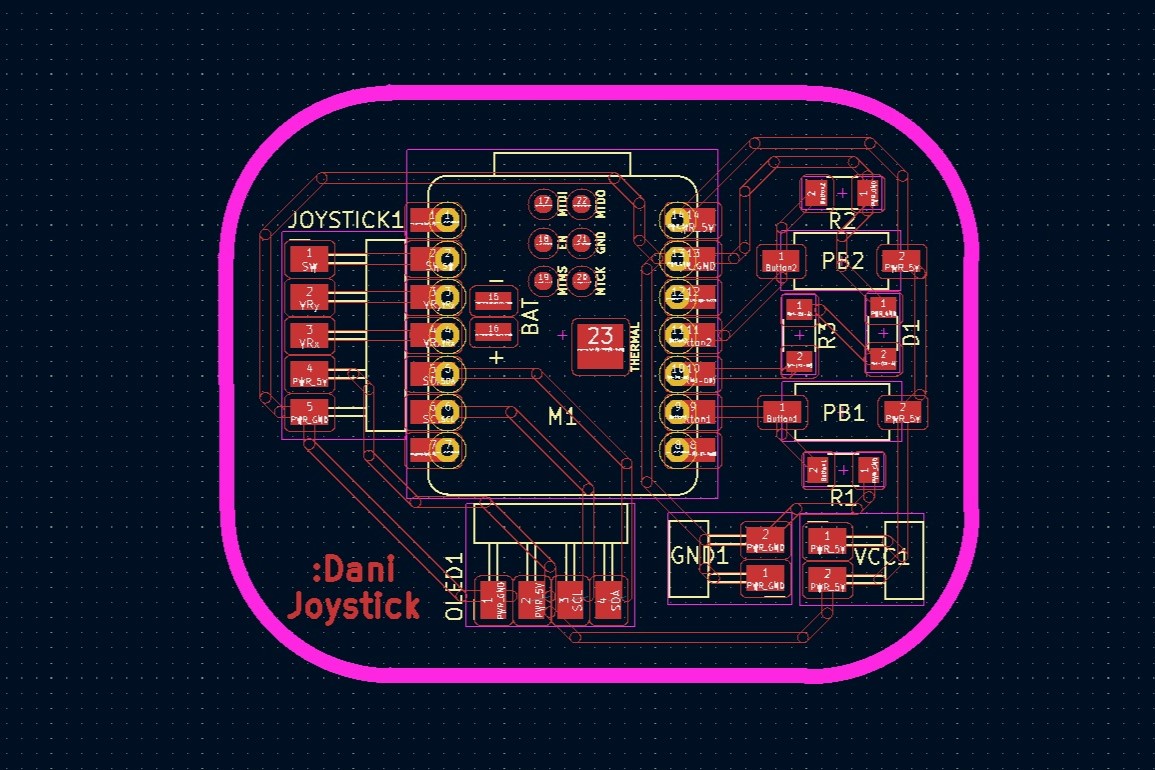
I designed the PCB in KiCad (as in Week 8), cutted it using the Roland SRM-20 (as in Week 4), and soldered the components.
About Input Devices
According to this week's group page, there are analog and digital input devices, which means that each one has a different type of signal to send to the microcontroller. In the group page there is an example of each one: a eart monitor for the analog input and a blood oxygen for the digital one. The heart monitor doesn't need to be connected to the microcontroller to be able to observer the signal, because the oscilloscope can receive these signals and show them graphically. Meanwhile, the blood oxygen need a microcontroller to send the information through a I2C protocol. It is important to select a different input depending on the needs of the project. Some examples of input devices are push buttons, potenciometers, switches, and any type of sensor.
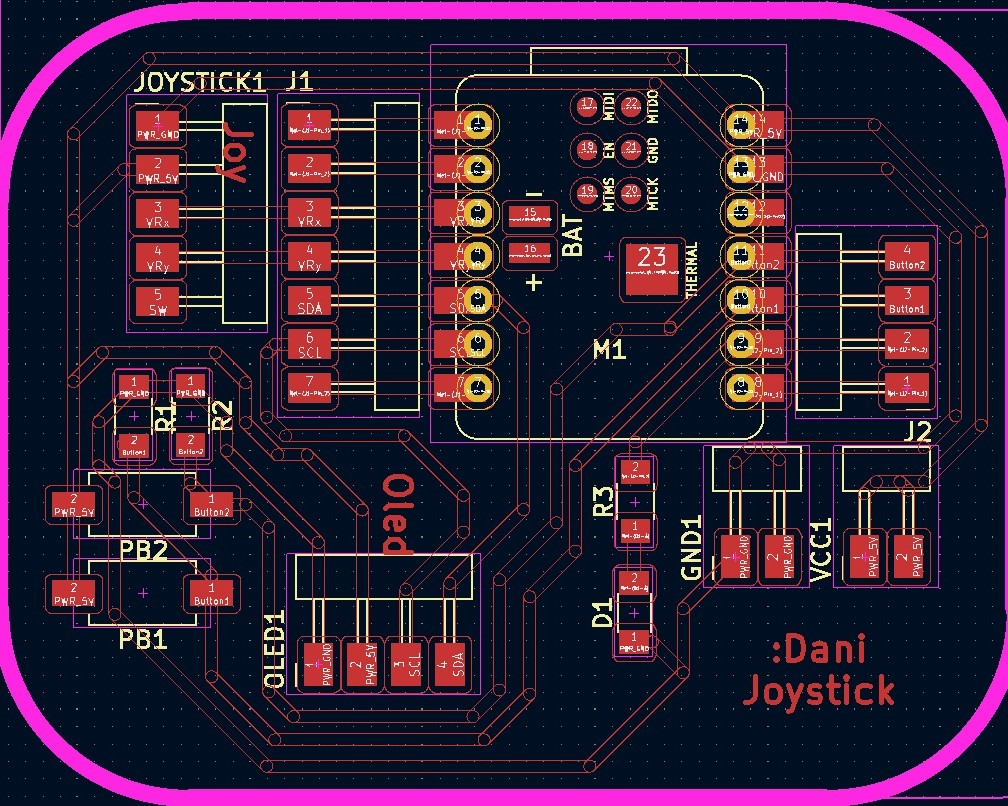
PCB Design
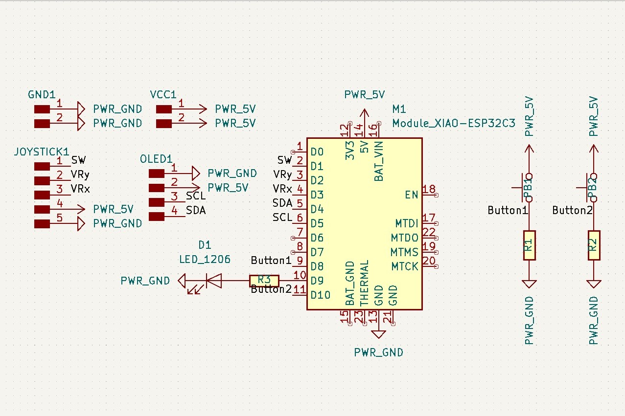
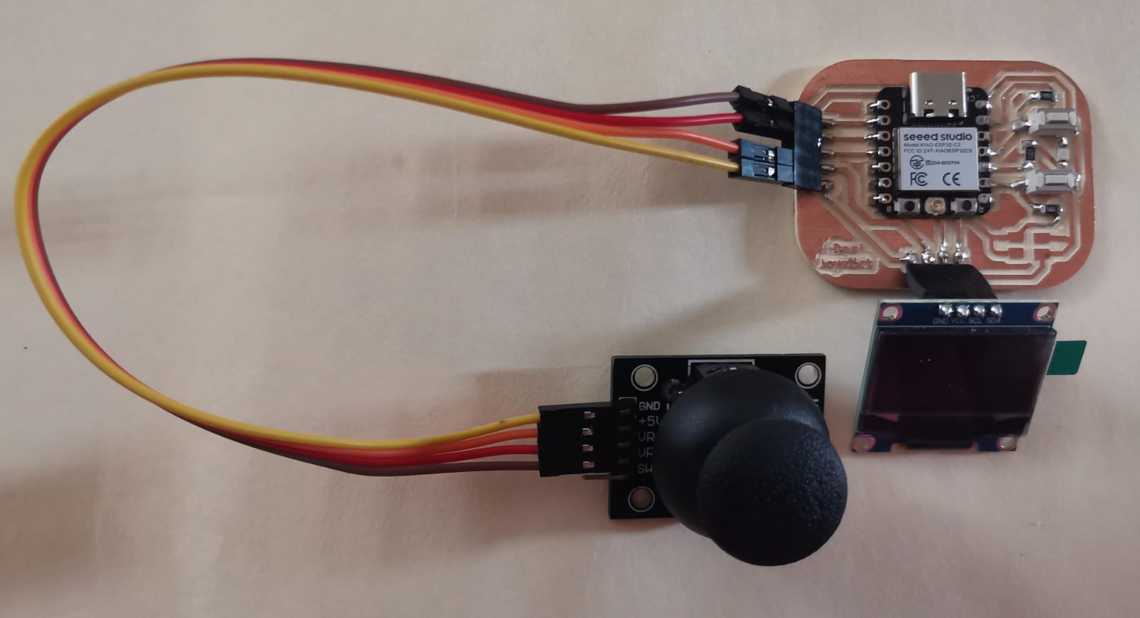
The idea for the final project is to have the motors controled by a joystick, but I don't want many cables going through the wheelchair. As the cables are to be avoided (at least for me), I used another Xiao ESP32C3 to connect them via bluetooth. So the PCB for this week had to also be done using this microcontroller, the joystick and the OLED.
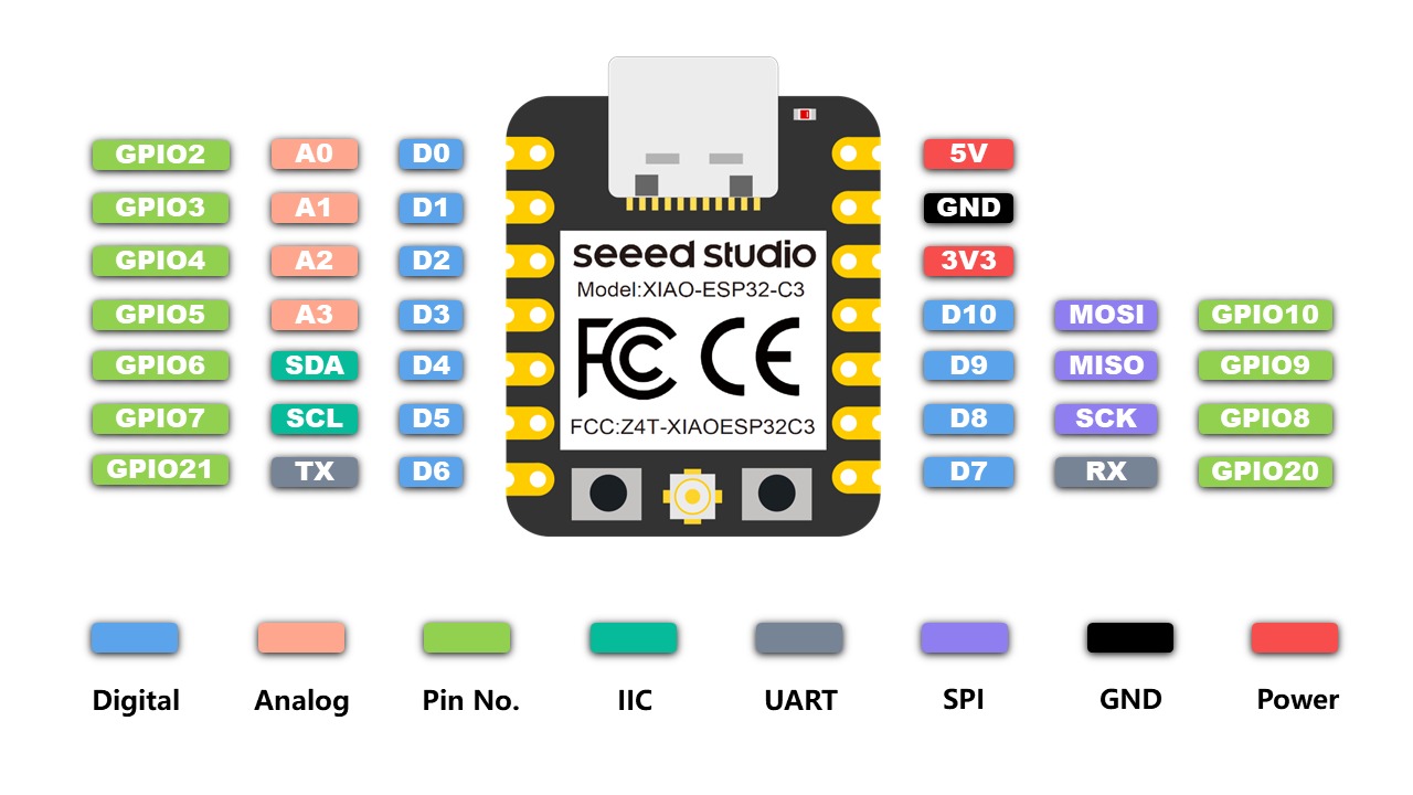
For this case I used the analog pins from the Xiao and had to select them according to its pinout:
First Try
For the PCB I located the analog pins that I wanted to use to send the joystick signals and aligned the pinheaders to them. I also put two push buttons, a LED and some extra pinheaders for all the xiao pins just in case.
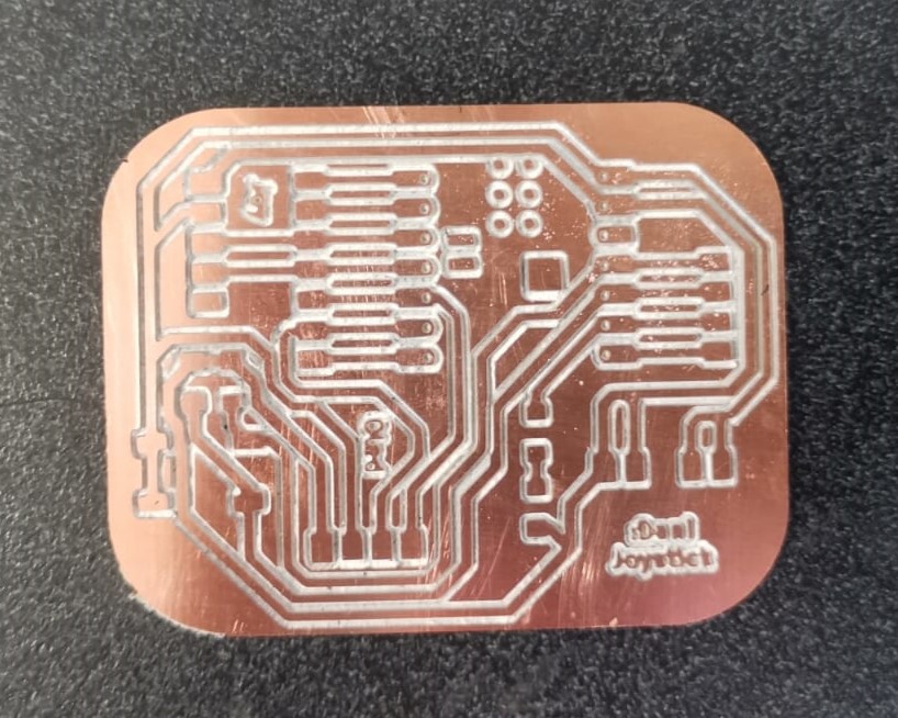
Although I review all the connections and so on, somehow the PCB didn't work as expected. The problem was that I couldn't turn on the OLED and the rest of the pins didn't seem to send any signal. I still don't know exactly which was the problem, but my theory is that I didn't put the insulation tape correctly beneath the microcontroller.
Second Try
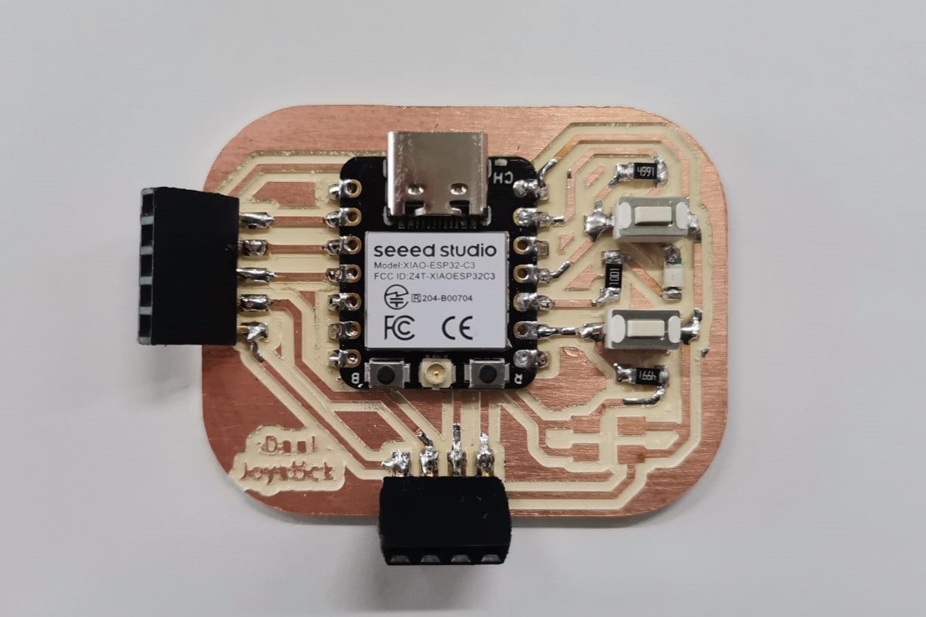
Since the previous PCB didn't work and I couldn't tell the problem (in order to solve it), I decided to make a new PCB. The second try was better and I was able to use it. For this PCB I didn't put extra pins (there were extra pins just for GND and VCC) I verified all the conections in the KiCad program. Then, after soldering the components, I made sure that the insulation tape covered the back of the microcontroller correctly, that all the paths had continuity and that the LED turned on using the multimeter.
Programming
Turn On OLED
At first, I tried to use the libraries necessary to use an OLED with Arduino, but it didn't work. So I searched for an answer and ended up with a very useful tutorial:
Then I copied the code to verify its funcionality, changed the font and added a blinking LED to make sure that the code was uploaded in case something went wrong:
Here the main problem I had was in the void setup(), because I had the setI2CAdress wrong, which meant that the code was sending everything to an OLED that wasn't even there. I solved this by looking at the back of the OLED:
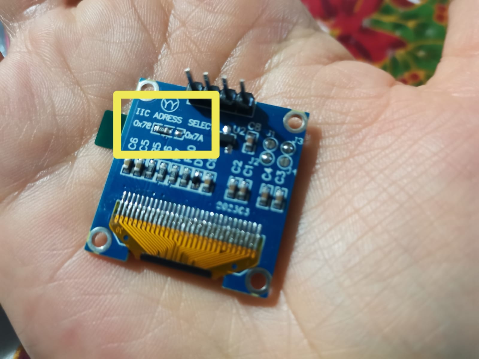
There, the I2C adress is the one that has the resistor, which in my case was the 0x78. So I wrote that in line 33 of the code.
Joystick
In the case of this week's task I wanted to use a joystick as the input device and show a message in the OLED indicating the direction in which the joystick is pointing. This with the purpose of implementing it in the final project by sending the directions to the microcontroller and then to the wheels. The connections went this way:
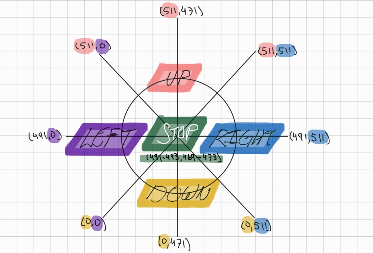
First of all, I adjusted the values sent from the joystick to make them smaller (they were from 4,000 and felt them too big) by dividing them by 8. Then I had to map the signals from the joystick to know when the code had to show which message. So I made a drawing to write the coordinates of some positions:
Finally, I applied that to the code and uploaded it to the Xiao showing the X and Y coordinates, as well as the direction in which the joystick is pointing:
Here, the main problem was that Arduino IDE sent the following error:
E (11854) ADC: ADC2 is no longer supported, please use ADC1.
Then I searched about this error and concluded that I had to change the pin I was using for the VRx (that was the ADC2) and connected it to the next one. This worked and then the only remaining task was to center all the text in the display.
Useful links
OLED
- Connecting OLED Displays with Seeed Studio XIAO ESP32 C3 - With Code (YouTube)
- Two OLEDs with ESP32 (GitHub)
- Download U8g2 Library (Arduino Reference)
- Install U8g2 Library (GitHub Tutorial)
- U8g2 Library Reference (Arduino Reference)
Files
Final PCB
- Traces (.rml)
- Outline (.rml)
- Traces (.svg)
- Outline (.svg)
- First try of the PCB (.zip)
- Second (and last) try of the PCB (.zip)