4. Electronic Production
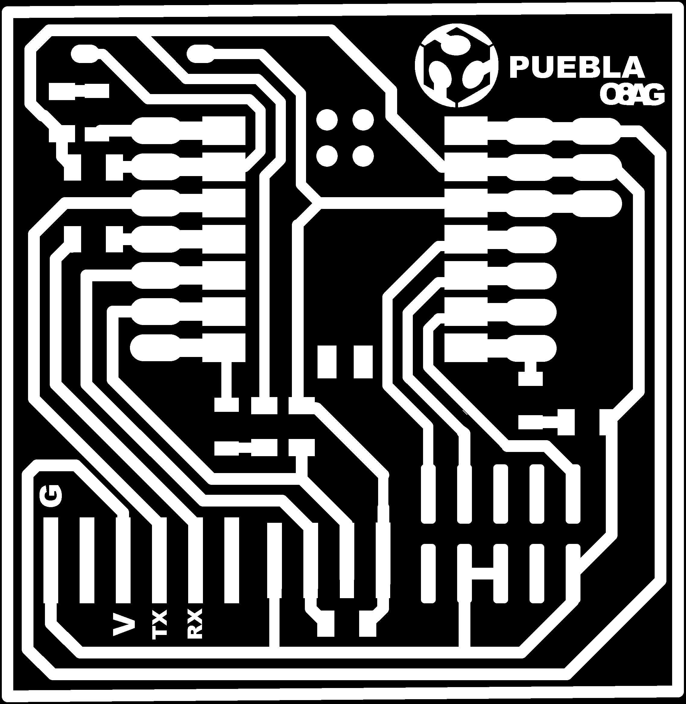
During this week we learned about electronics production with PCB milling. For the cutting we used the ROLAND SRM-20 Mini-Mill, which is a CNC able to do the detailed cut for the PCB. This works by carving away the copper around the paths to create the circuit traces. The machine uses .rml files, so I had to do the conversion from the .png pictures.
Knowing the ROLAND SRM-20
To know about the ROLAND SRM-20, the local instructors gave a lesson about it, as well as the summary and important points in this week's page . The SRM-20 is able to cut modeling wax, chemical wood, foam, acrylic, polyacetal, acrylonitrile butadiene styrene (ABS), and printed circuit boards. It engraves along the x and y axis, and cuts along the z axis. It has an operation speed among the range 6 - 1,800 mm/min and an spindle rotation speed of 3,000 - 7,000 RPM.
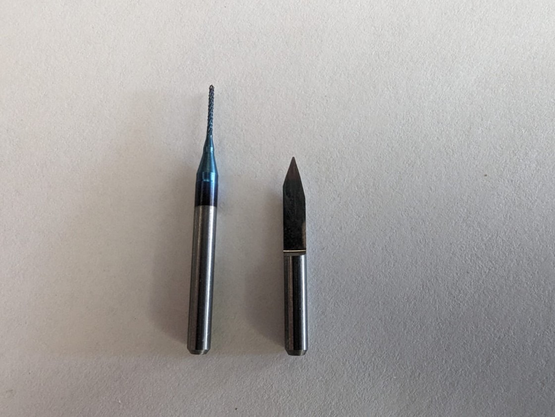
Regarding the tool we all used a 15 degree V-bit (right) for engraving and a 0.8 mm diameter two flute end Mill (left) for cutting.
And here are the parameters for the machine and the circuit:
- Drill Hole Size: 0.8 mm
- Material: FR-1
- Minimum Clearance: 0.010 mm
- Minimum Trace Width: 0.020 mm
- Number of Layers: 1
- Offset number: 2
- Maximum Depth: 0.1016 mm
Toolpath Creation
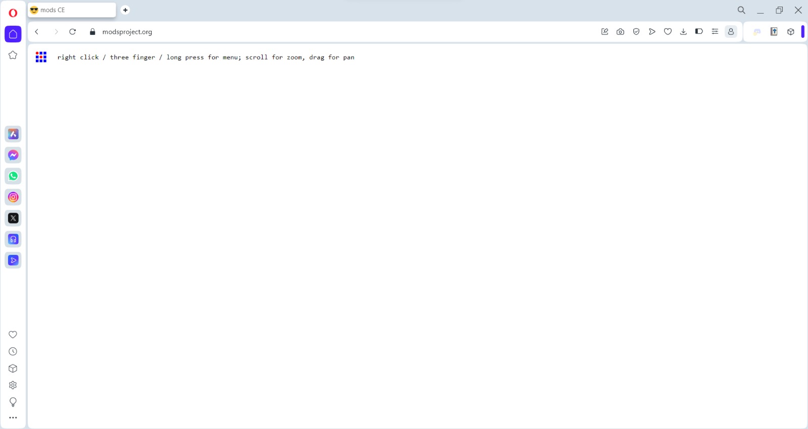
Now that I had the parameters I went to the MODS page in order to create the toolpath. It seemed like a lot of steps when I saw the page for the first time, but it was pretty quick and easy.
- First of all, it opens the website:
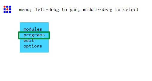
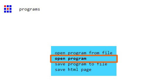
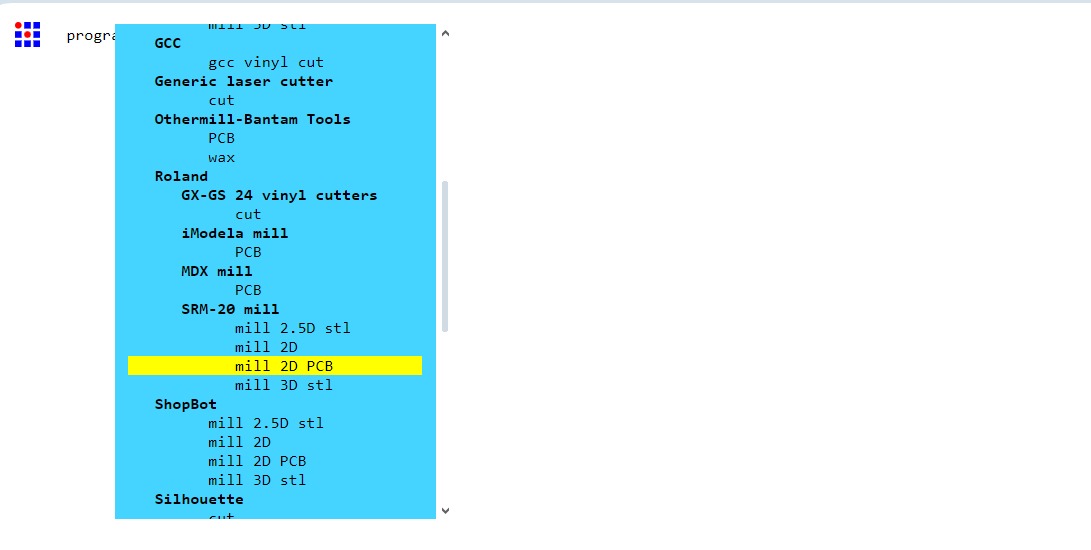
- Then I right-clicked on whatever part of the webpage, selected "programs" (green rectangle), then "Open Program" (orange rectangle), and, finally, selected the machine (yellow rectangle):
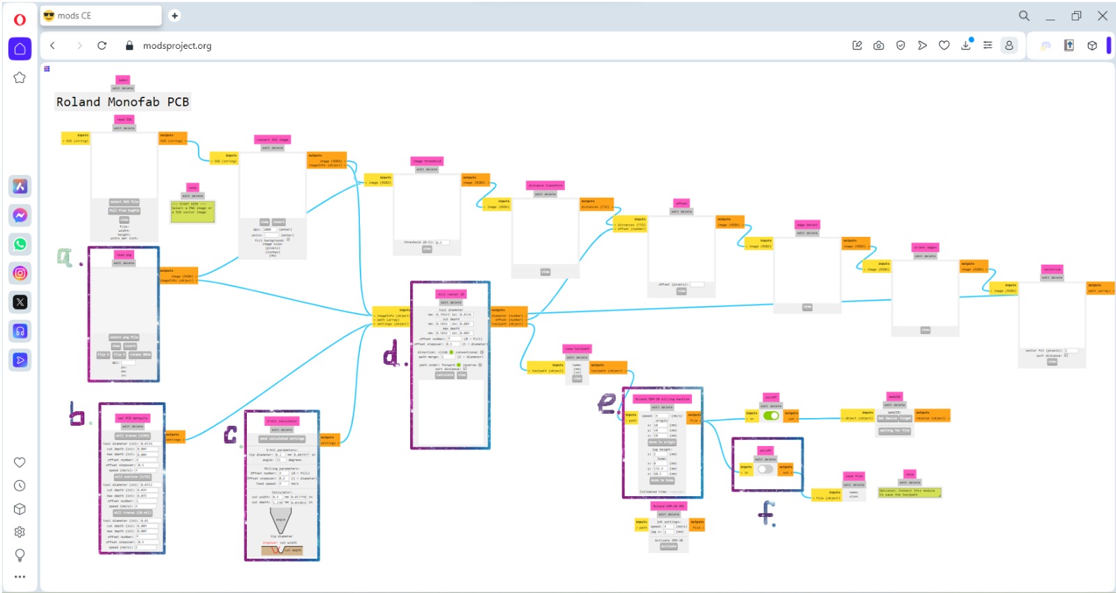
- It opens the following (I only edited the selected parts):
- a. Selected the png file (the white lines are the ones to stay)
- b. Clicked on "mill traces 1/64"
- c. Stayed the same
- d. Changed "Offset number" to 2
- e. Set x, y, and z origins to 0
- f. Enabled it
- Then I clicked on calculate (d. rectangle) and it automatically downloaded the rml file. However I could have a view of the toolpath by click on "view" (d. rectangle).
- For the "Outline" file I did the following:
- a. Selected the png file and clicked on "Invert" (the black line is the one to be cutted)
- b. Clicked on "mill outline 1/32"
- c. Stayed the same
- d. Changed "Offset number" to 1
- e. Set x, y, and z origins to 0
- f. Enabled it
- Then I clicked on calculate (d. rectangle) and it automatically downloaded the rml file. However I could have a view of the toolpath by click on "view" (d. rectangle).
For each one I did the following for the "Traces" file:
Board Milling
- For the milling I downloaded the software "VPanel for SRM-20" and the MonoFab driver to control the cutter.
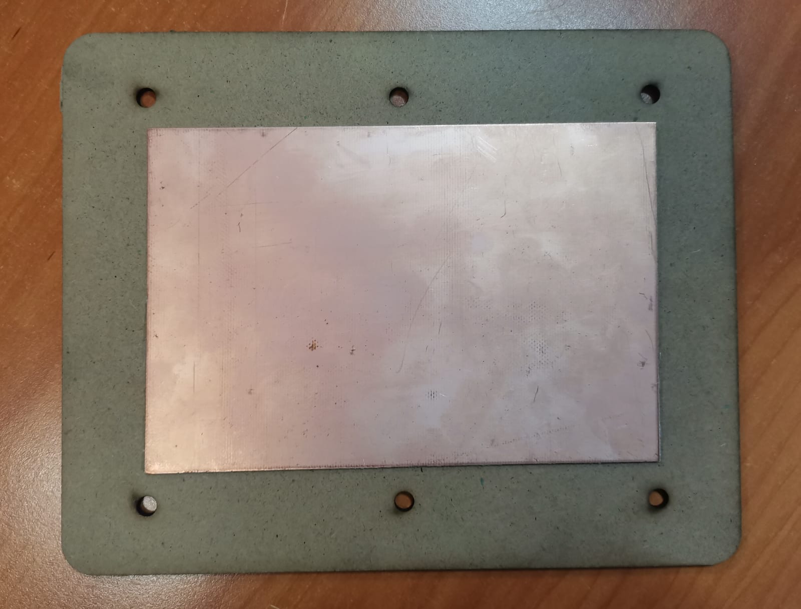
- I firstly secured the PCB to the sacrifice plank using double-face tape and made sure that the placed tool was the engraving one. The sacrifice table has holes so I could secure it to the working table of the machine with screws.
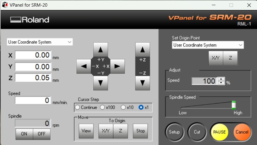
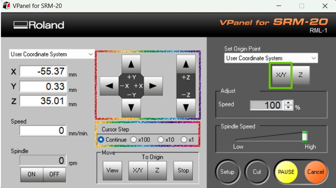
- Then I adjusted the x and y axis to the lower left corner using the arrows and controling the cursor step. Then clicked on the "XY" to set the origin point (green rectangle).
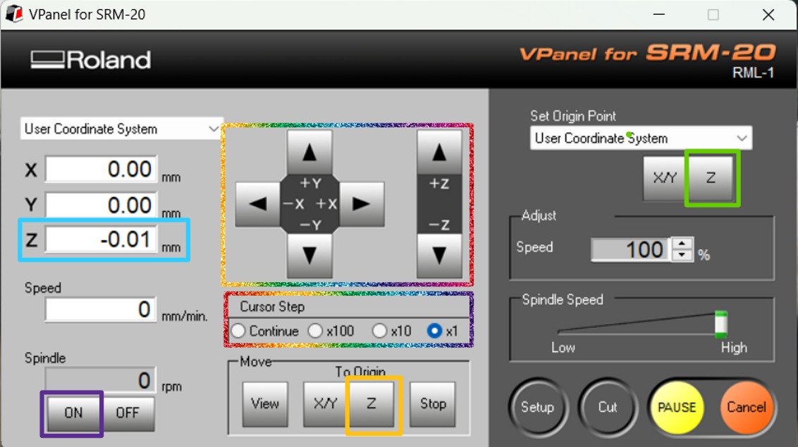
- To adjust the z axis I put a paper between the PCB and the tool and moved the tool using the arrows. But I first used the continue cursor step to get closer to the PCB, then the x100, then x10, and finally the x1 to prevent the tool from crashing into the PCB. Once the paper wasn't moving at all, I clicked on the "Z" to set the origin point (green rectangle). I moved the tool upwards, removed the paper and clicked on the "Z" to move to the origin in the z axis (yellow rectangle). After that I used the x1 cursor step to lower the tool one unit and activated the spindle (purple rectangle) to make sure that it touches the PCB. I clicked on the "Z" again to set the origin point.
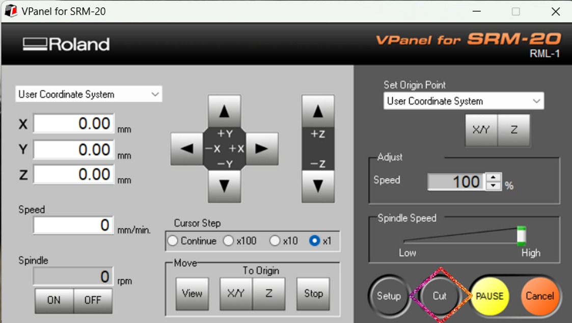
- Now that everything is set up, I clicked on the "Cut" button and chose the file.
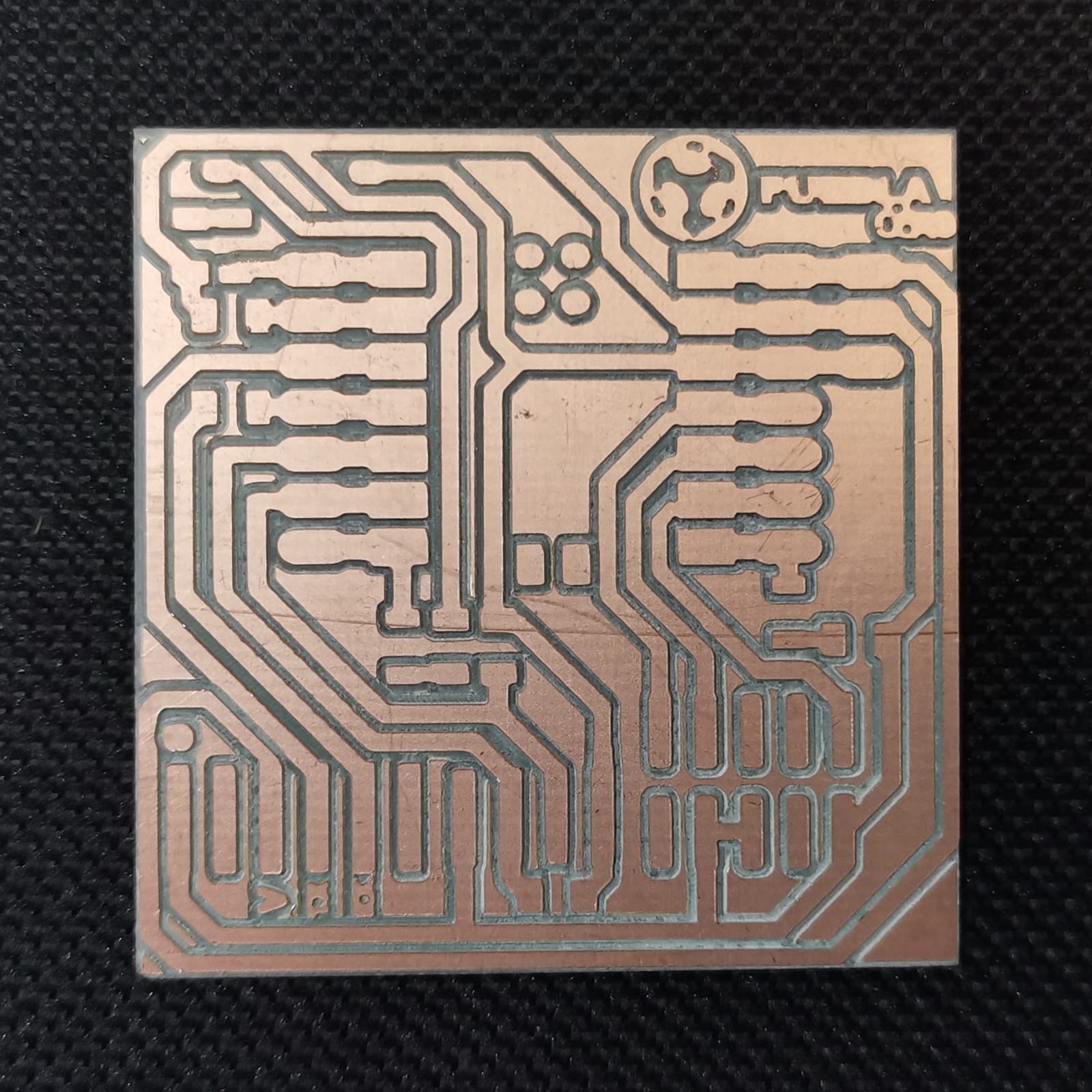
- Finally, it made the engraving and I followed the same steps for the outline cut.
- The final result:
I had only one problem, cause when I did the cutting of the outline, I took with the tool all the sacrifice plank. This happened when I was aligning the z axis of the cutting tool. When I made the small revolution to mark the point and lowered the tool with the Z arrow, it lowered more than expected. Then I stopped the machine and rose the tool, taking the sacrifice plank with it (it got stuck) and the screws as well, which were attached to 3D printings to the working table. So the 3D printings broke and let the plank loose. However, then I learned that when something like that happens, it is better to rise the tool while spinning to avoid breaking everything.
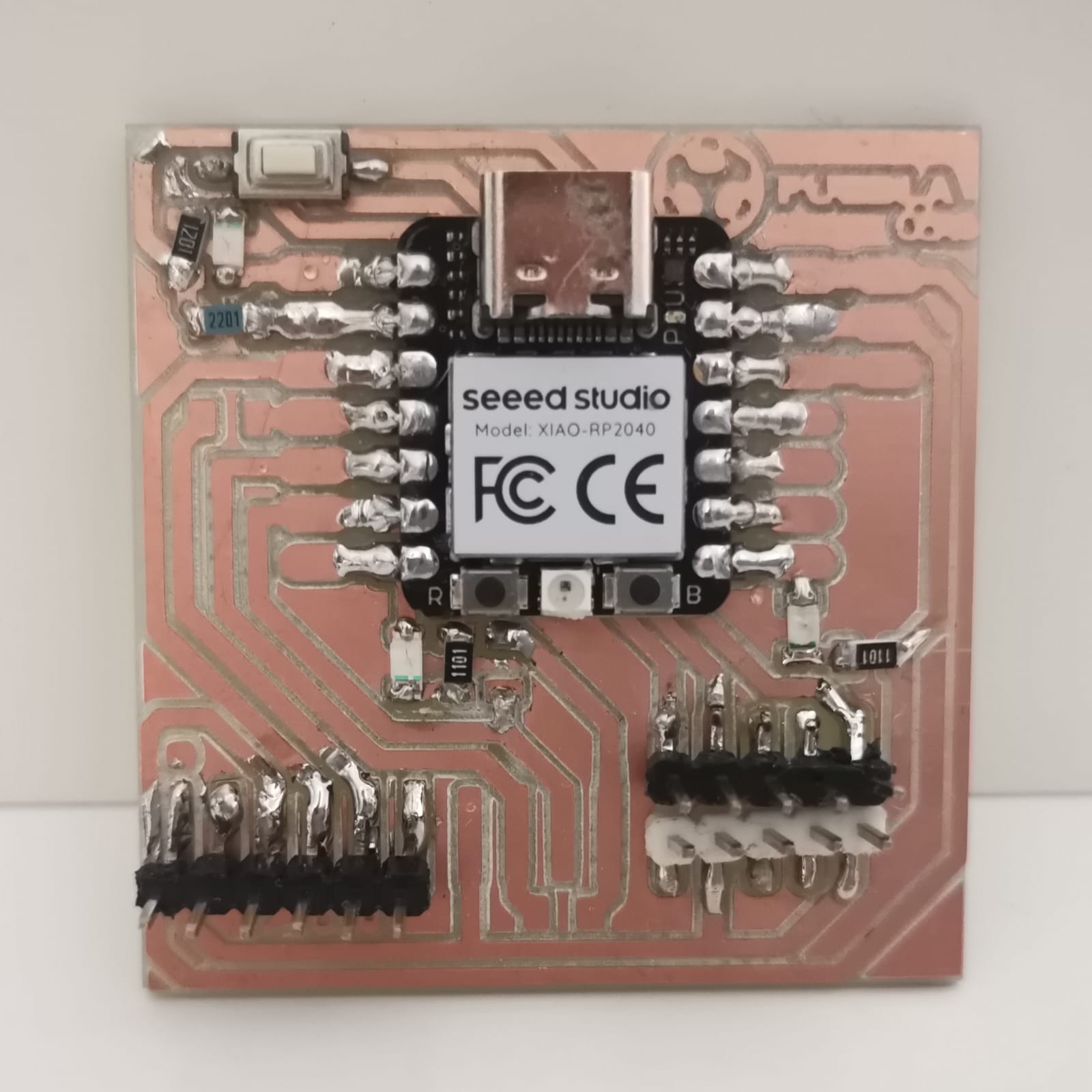
Components' Soldering
I don't have much practice soldering, but it worked. For this I used the soldering iron and tin thread. The components were the following:
- 1 Xiao RP2040 (according to the local instructors, it is easy to solder and to program, to which I agree as I had used Attiny and ATmega in my previous career classes)
- 3 Resistors 1kΩ
- 1 Resistor 2.2 kΩ
- 3 LEDs SMD
- 1 Push Button
- 16 Pinheaders
Firstly, I taped the bottom of the microcontroller with insulation tape to prevent its metal parts from short circuiting. Then I soldered the Xiao, although I think I may have used many tin thread for that. On second place, I soldered the resistors and LEDs. At first, I thought it would be quite difficult, but I put a little bit of tin thread on the metal part of the resistors and LEDs so that when I colocated them over the PCB and heated the copper with the soldering iron, the tin would melt and stick to it. Finally, I soldered the push button and the pinheaders. However, I had a little bit of a trouble soldering the pinheaders, because at first the black and white ones were touching one and other. But when I tried to solve it, I lifted some copper, although it didn't affect its functionality.
For the next time I think I will be more careful about the amount of tin thread I use, as well I will make sure that the components (in this case the pinheaders) aren't touching one another. I think I will be able to do the soldering faster too, cause this process took me most of the day (a few hours), but I was able to put all the components in the correct way:
Funciontality Verification
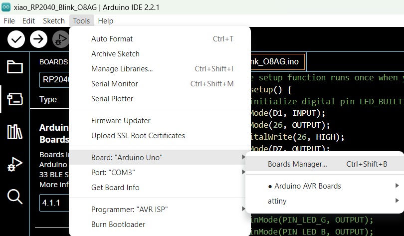
Finally, the local instructor provided us a program for the microcontroller, which turns on and off the LEDs. To upload the code to the Xiao microcontroller I used Arduino IDE, but in this software the on-board package named Seeed XIAO RP2040 is no longer available. For this reason I had to install it following the next instructions:
- On the interface go to Tools -> Board -> Boards Manager...
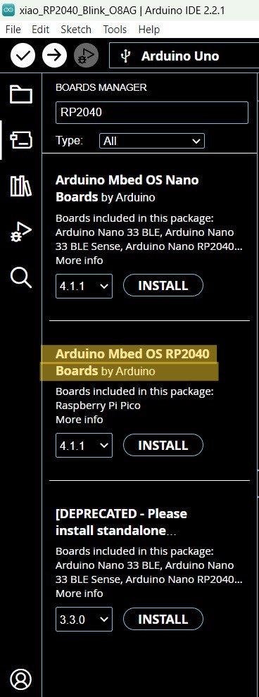
- Search for "RP2040"
- Select the option that says "Arduino Mbed OS RP2040 Boards" and click on "Install"
- And followed the installation instructions
Then I uploaded the code to the Xiao and tried it:
The code's purpose is to turn on and off the LEDs each second. While the red and greed LEDs turn on on their own, the blue one turns on when the push button is working.