9. Output Devices
This week was all about output devices, so I decided to work with DC motors, since I'd be using them for my final proyect. However, I had to design a new PCB, because I forgot to connect the voltage from the battery to the rest of the circuit (last week I only used two LEDs and a button, so I didn't need the power from the battery). This week the power from the battery wasn't as necessary as I thought (I discovered that two little DC motors may be moved with the computer alone), but it bothered me that the battery wasn't connected. I also would have needed to cut a PCB in order to connect the Xiao ESP32-C3 to a the PCB for the H bridge, so I thought that if I would be cutting again, I'd better join everything in one PCB (for more order and practicity). Even though I had some things to do, this week's page is a bit shorter than the previous ones, since I only changed the PCB done in week 8 and pogrammed (something I have already done in week 6).
The New PCB
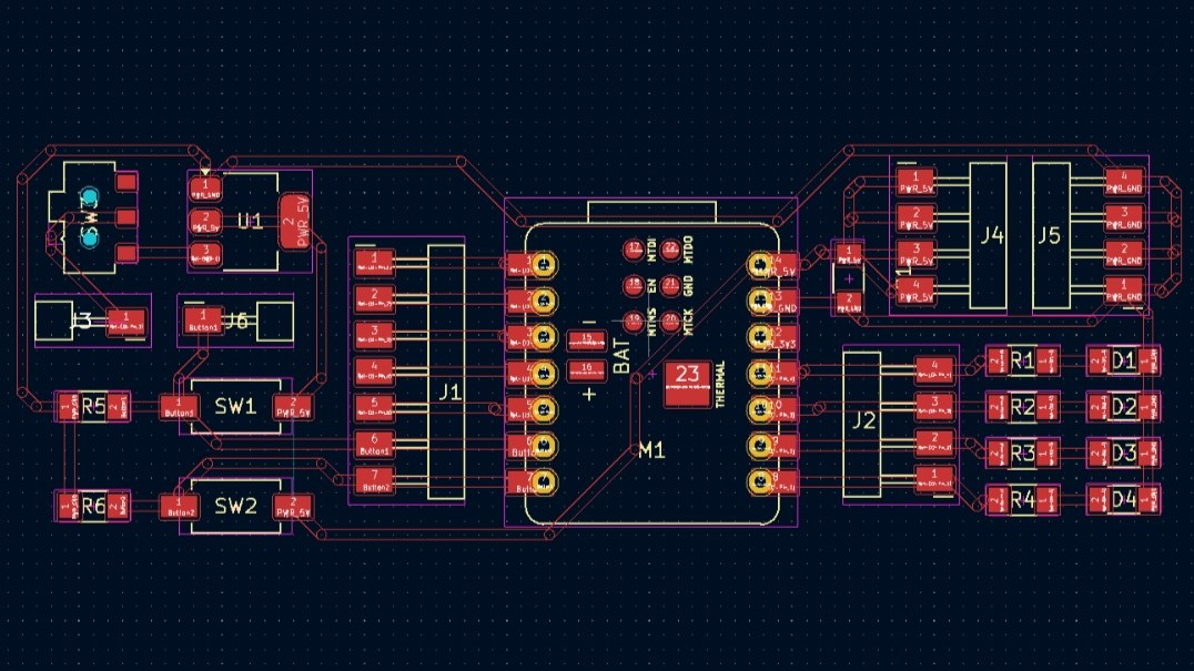
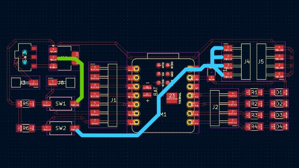
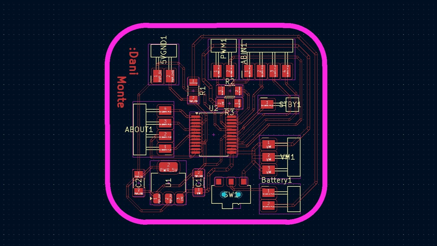
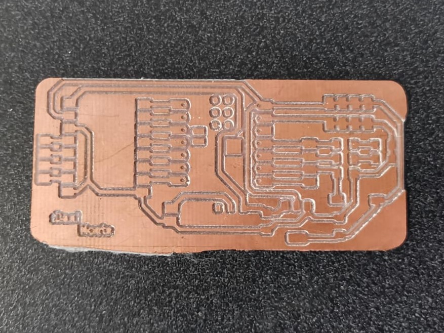
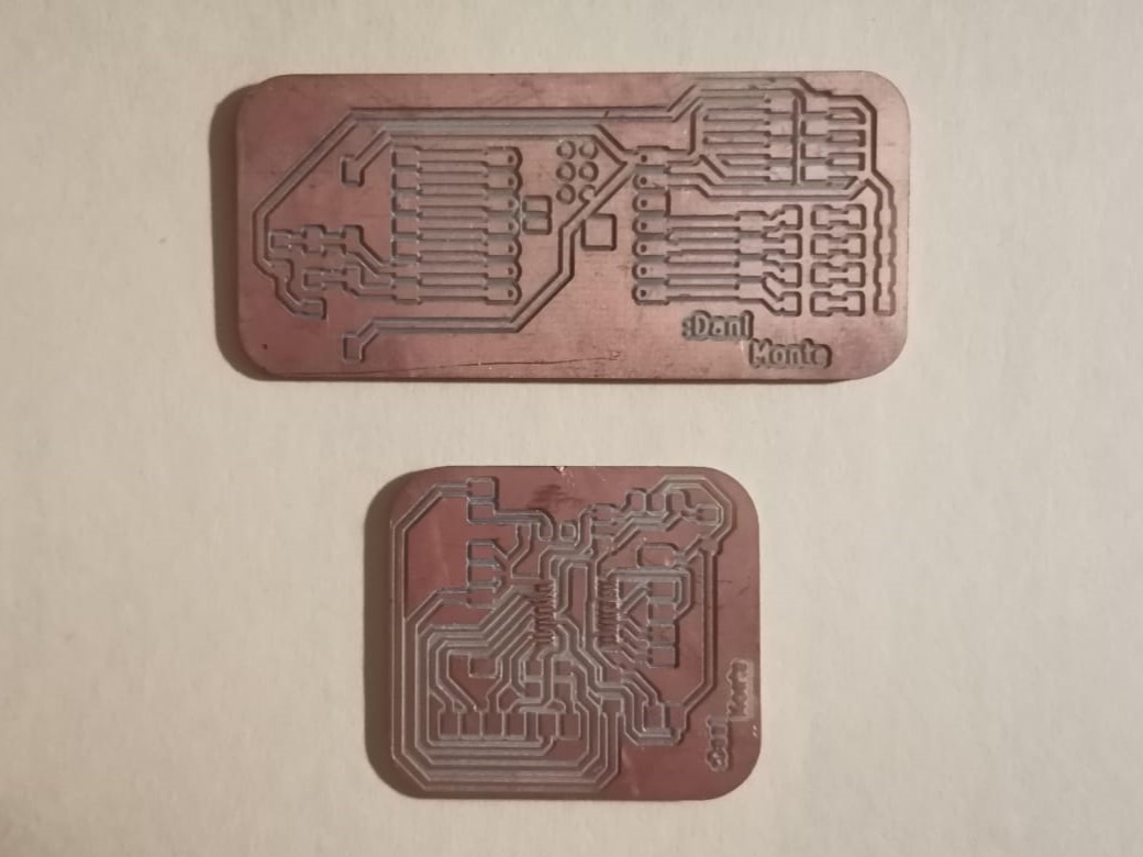
Originally, I had the PCB done in week 8, but I noticed that the battery was connected only to one push button, so it didn't really supplied voltage to the rest of the board. For that reason I had to redesign the PCB. The original PCB looked like the first picture, and the voltage paths were as shown in the second picture. However, I also thought of a PCB for the H brigdge (this PCB would control the motors) designed as in the 3rd picture.
But when I saw the voltage problem, I though that if I was already going to cut a PCB, I might as well join everything together. And that's the reason I had to desolder everything from the previous PCB and why I cut a new one and pass the Xiao ESP32-C3 to it.
Design
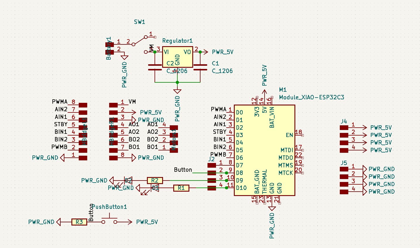
The design consisted on joining both designs (not forgetting to connect the voltage) and having some extra pins just it case. I used KiCad for the design of the PCB (as in the previous week) and it had the following components:
- 1 Xiao ESP32-C3
- 1 H Bridge
- 2 LEDs
- 1 Push Button
- 2 Resistors (1 kΩ)
- 1 Resistor (4 kΩ)
- 1 Capacitor
- 1 Sliding Switch
- 1 Regulator (AMS 1117)
- 2 DC Motors
- 22 Pinheaders
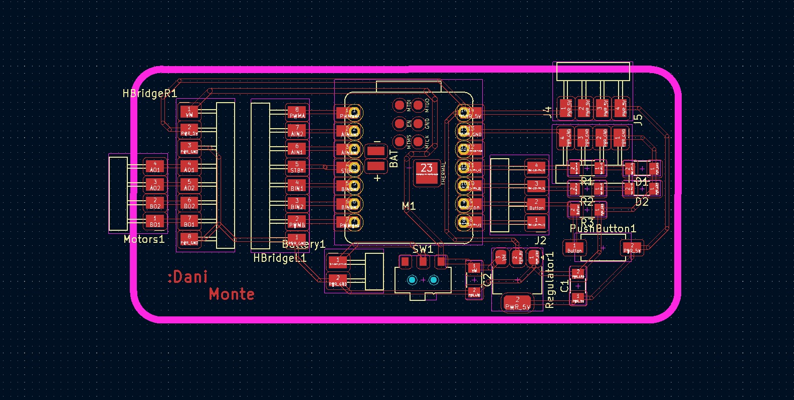
The PCB had all the mentioned components and I designed the schematic as shown in the first picture, there I also added some extra pins to all the pins of the Xiao and 5 extra pins for voltage and GND. Then I went to the PCB editor and joined all the corresponding paths (second picture). At first, I had problems connecting the voltage paths, because they crossed with other paths. But I found a space and was able to connect everything. Finally I chequed that all the components were connected correcly and downloaded the svg files of the paths and the margin.
Cutting
After I had the svg files, I went to the modsproject page and created the toolpaths using the week 4 documentation to create them.
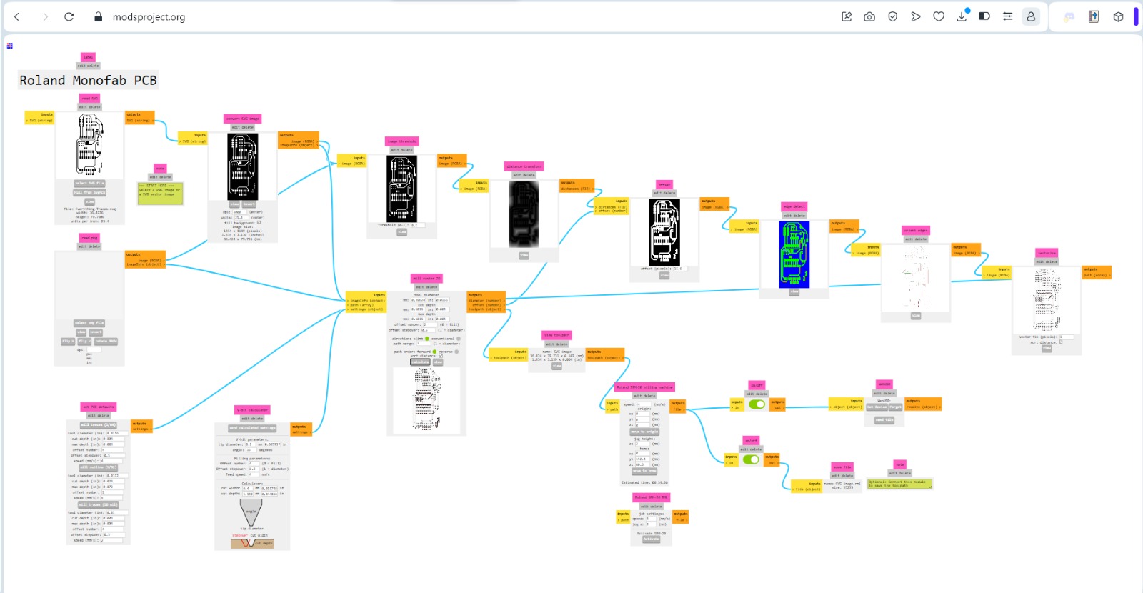
Mods page to make the traces' toolpath
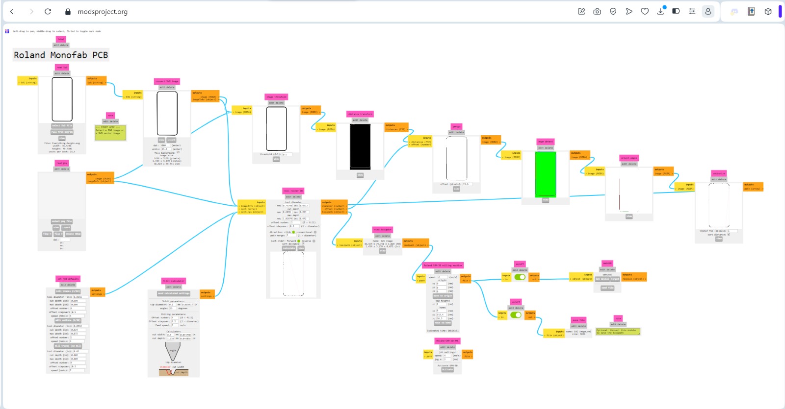
Mods page to make the outline's toolpath
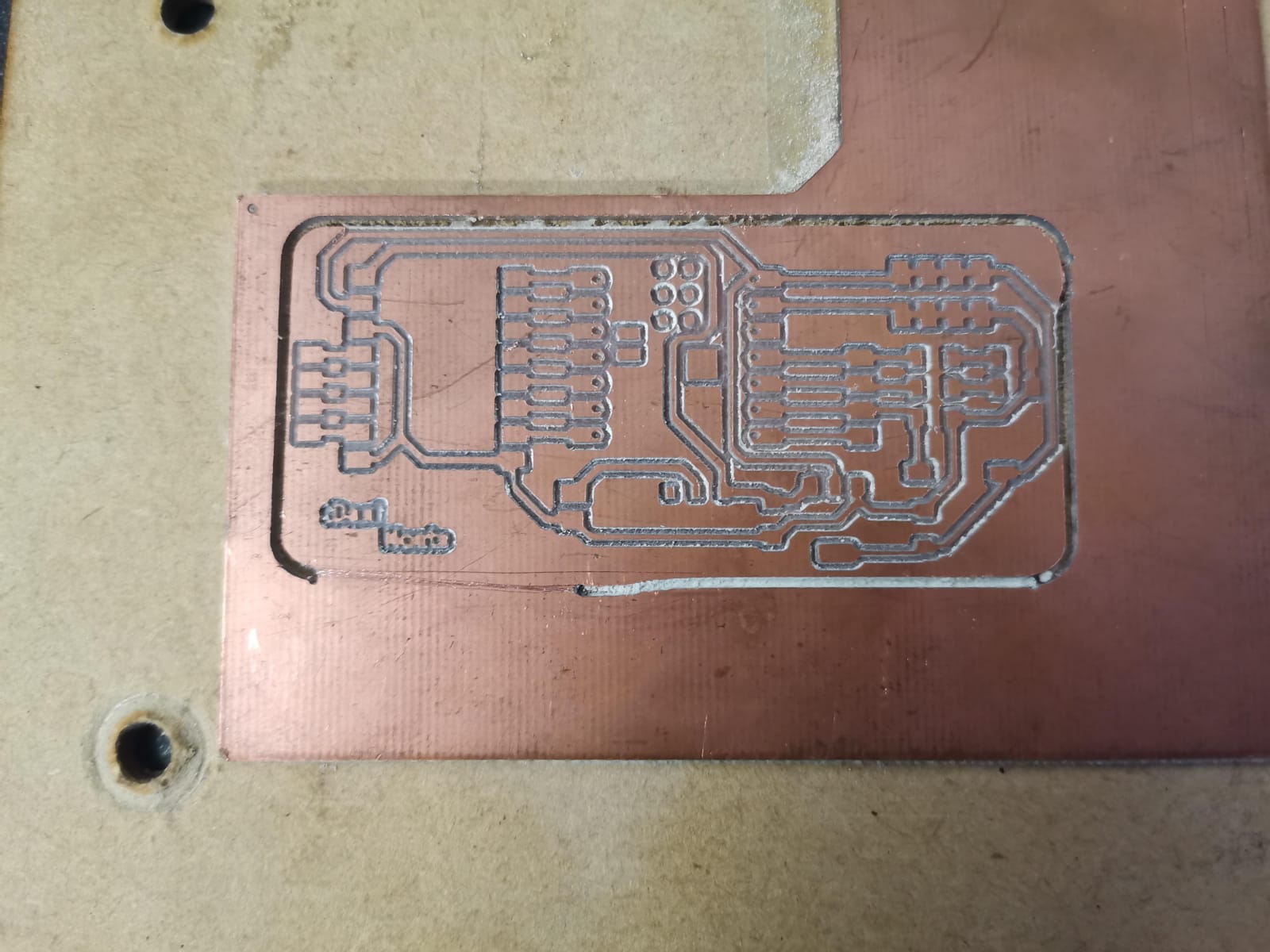
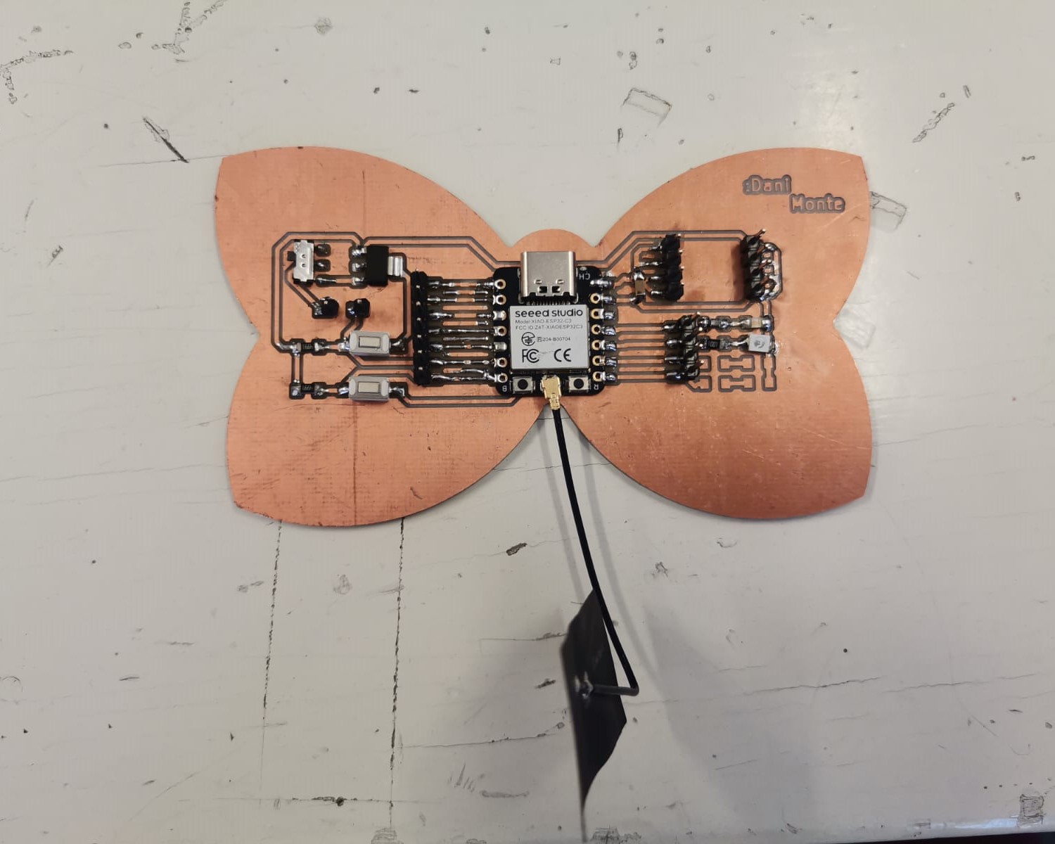
Finally, I cut it in the Roland machine. However, I didn't paste the copper plate to the sacrifice table, so it detached almost at the end of the margin cut (1st picture). Although it destached, I was able to remove it by cutting along the rest of the edge with a cutter to push it and drop it (2nd picture). But this time my PCB didn't have as smooth edges as the one from the previous week and the one I cut from the original plans, because I did, in fact cut the PCB for the Xiao alone (with the voltage connected) and the one for the H bridge, but then I had many problems soldering the chip, because the PCB itself wasn't well cut (3rd picture) and I had to mark the spaces for the chips footprints with a cutter (but I removed part of the copper).
Soldering
First of all, I had to desolder the previous PCB:
A friend, Emmanuel, showed me how to desolder using the heat gun and the soldering iron. He showed me that by helping me desolder the Xiao. The way to desolder is by applying the heat at a certain distance (no completely directly) so that the components don't get burn and once the tin is more malleable, the component is ready to be removed with tweezers. It is important to have enough patience and not apply directly the heat to avoid burning the components. I was able to remove safely all of the components, except a LED (I melted the coating).
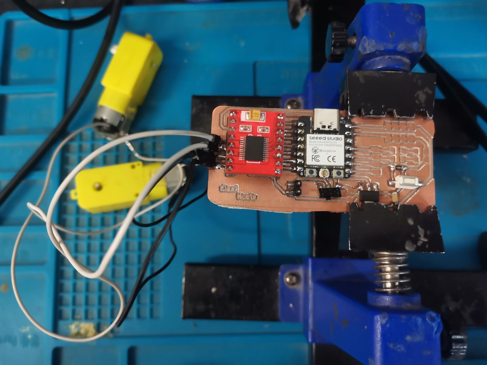
When soldering, I followed the PCB image to place the components in the correct paths:
I didn't solder all the component considered in the previous picture (I plan to solder them just in case I need them). I soldered the Xiao, the H bridge, the two motors, the battery pins, the switch, the regulator, the push button, and the capacitor.
Programming
I kept the PWM at maximum for both motors, because I only wanted this time to work with changing the direction and with connnecting the external battery. The code has the purpose to move both motors in a direction (and turn on a LED) and then change it while pressing the push button (and turn the LED off). Also I used Arduino IDE to upload the code and then connected the battery to power the circuit as I'd be doing in the final proyect.
Measure Power Consumption
To measure the power consumption of an output device we did it in the group page. Here the instructors let us know (as well as in the local lesson) that it isn't possible to directly measure the power, so we had to use the relations given by all the parameters (voltage, resistance, current, and power):
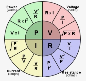
Knowing the previous formula we were ready to know the power consumption of any output device. In overall, there are certain steps to follow in order to know its power consumption. There is also different power consumption, which can be measured by how much current is required by the device when connected to a power supply, the nominal current, the maximum current, and the average current.
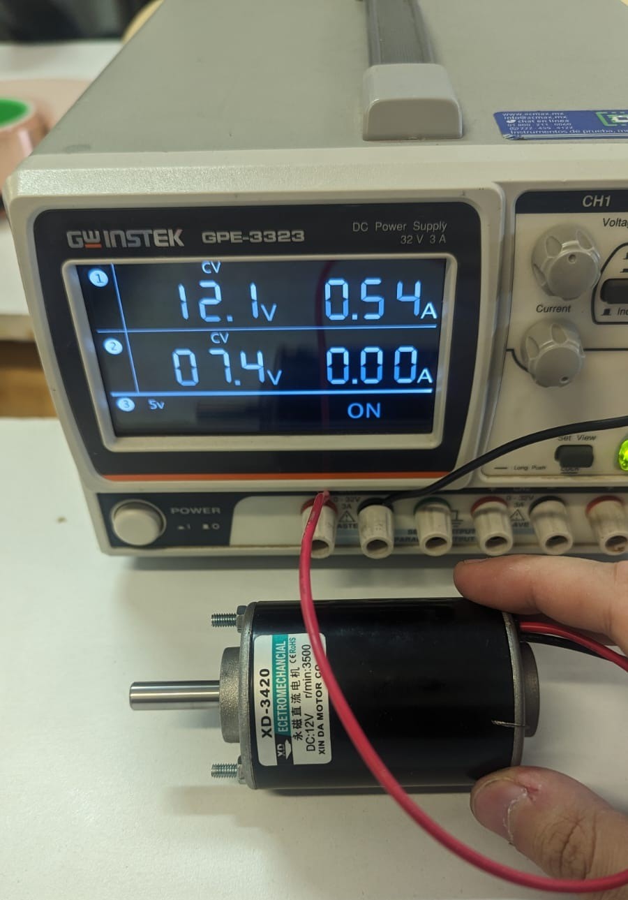
Using Power Supply
By using a power supply, what I unterstad by it, is much more like letting the output device freely in the wild and observe current it demands. We used a Handson Technology 3420 Dual Ball Bearing Long Life DC Motor. In this case, the voltage and current are the ones shown in the display of the power supply and we used the formula P = VI to calculate the power consumption: P = 12.1V*0.54A = 6.534 W
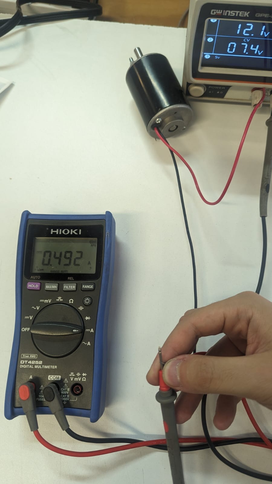
Using Multimeter
When using the multimeter, we measured the nominal, maximum and average current with a stable voltage of 12.1 V. This was done by wiring in series the multimeter. The first measure was when the motor was stable, then we confirgured the multimeter to get the maximum value measured, and finally to get the average current. We used the formulas:
- Stable motor: P = 12.1V*0.492A = 5.953 W
- Maximum current: P = 12.1V*1.101A = 13.322 W
- Averge current of 0.515 A: P = 12.1V*0.515A = 6.2315 W
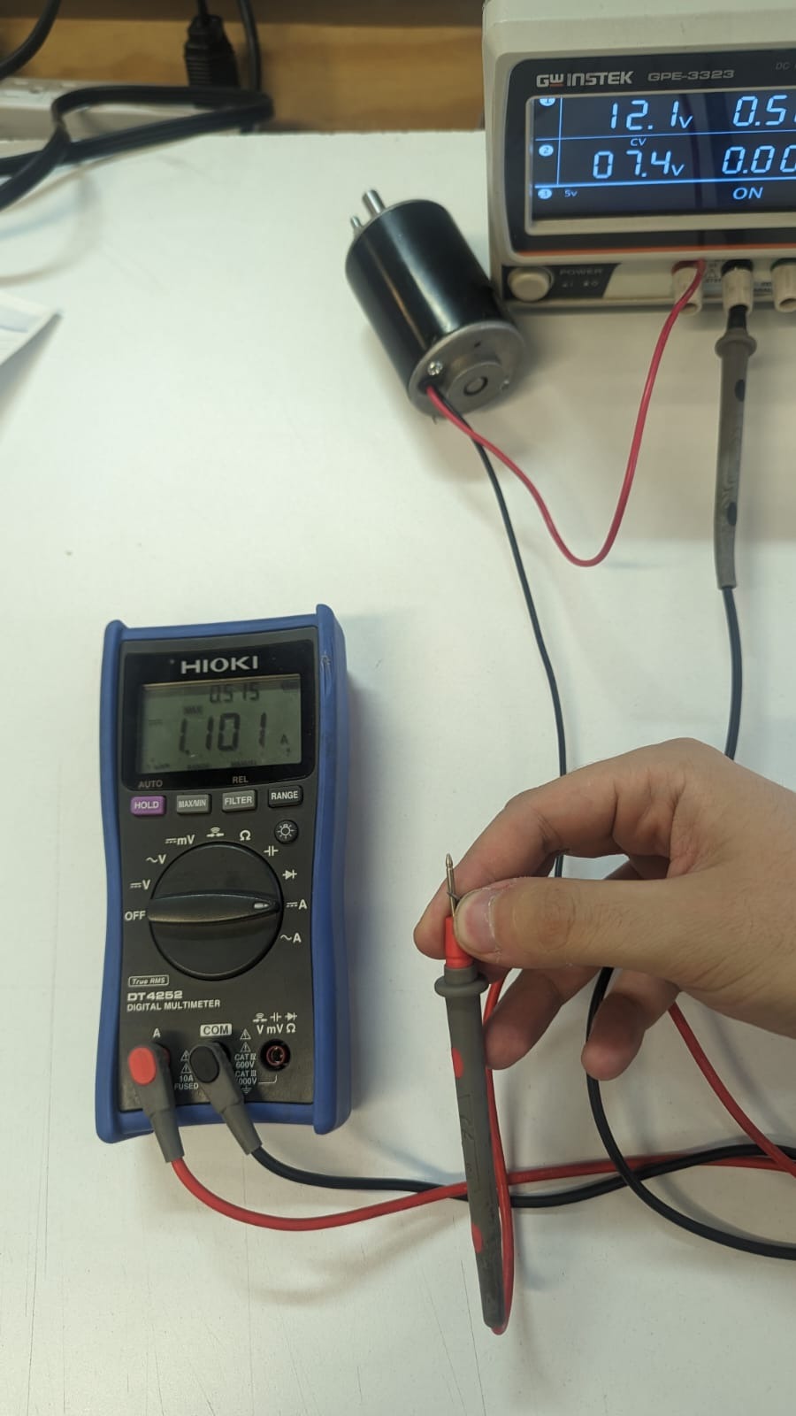
This showed that we needed a driver that stands the the peaks of the motor.