Week 9
Output Devices
- Measure the power consumption of an output device
Output Devices
For this week we were asked to measure the power consumption of an Output device. We decided on taking measurements on 3 output devices
- A polulu 125:1 Metal Gearmotor 20Dx44L mm 6V CB
- A Handson Technology 3420 Dual Ball Bearing Long Life DC Motor
- A TowerPro MG995 Servo Motor

However before taking any measurements we needed to understand how power worked, what we are measuring and the relation between this forces in electricityy first let's define the main variables in a circuit Current(I), Voltage(V), Resistance(R) and power(P).
Now that we knew the concepts our instructor told us of this really easy to understand graph, which tells us the relationship between them
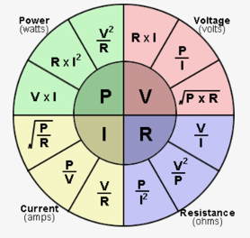
As told by out instructors measuring power direclty isn't something that can be done easily which means we should be using the formulas in the previous graph which meant we had to take at least a combination of measurements. At first we were thinking of measuring the resistance of our motor and then using the voltage given we could caculate the power, however this wasn't as easy as expected. One of our instructor commented to us that motor are an inductive load which meant that Ohm's Law is not directly applicable because these components do not follow a linear relationship between voltage and current like resistors do. Therefore we needed to measure the current and the voltage and then multiply them to get the power, for which we have a few options.
- Using one of our DC power supplies which tells us how much current it's being used
- Using our Hioki multimeter which we used on out last group assignment, on current measurement.
- Using a USB Current Voltage Checker.
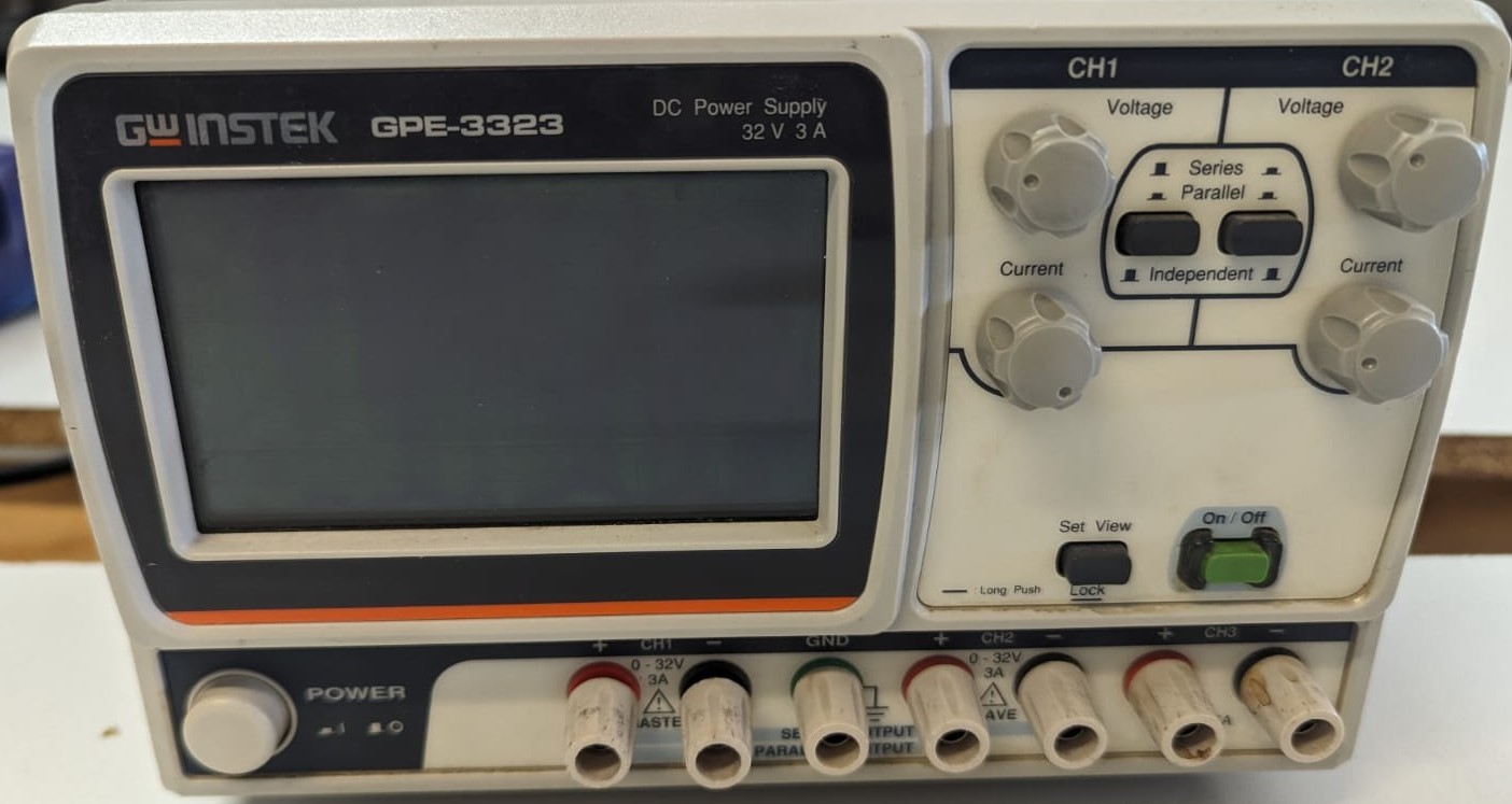
First we tested our small DC motor. Using our Gwynstek brand power supply. Which we can see below, this power supply has 3 voltage channels the first 2 being regulated in both voltage and current using the knobs on the top part of it, and a third channel which always give 5V. It also has a screen which shows us the value of the current and voltage being used on the channels. To wire it we have banana plugs on the lower side of it.
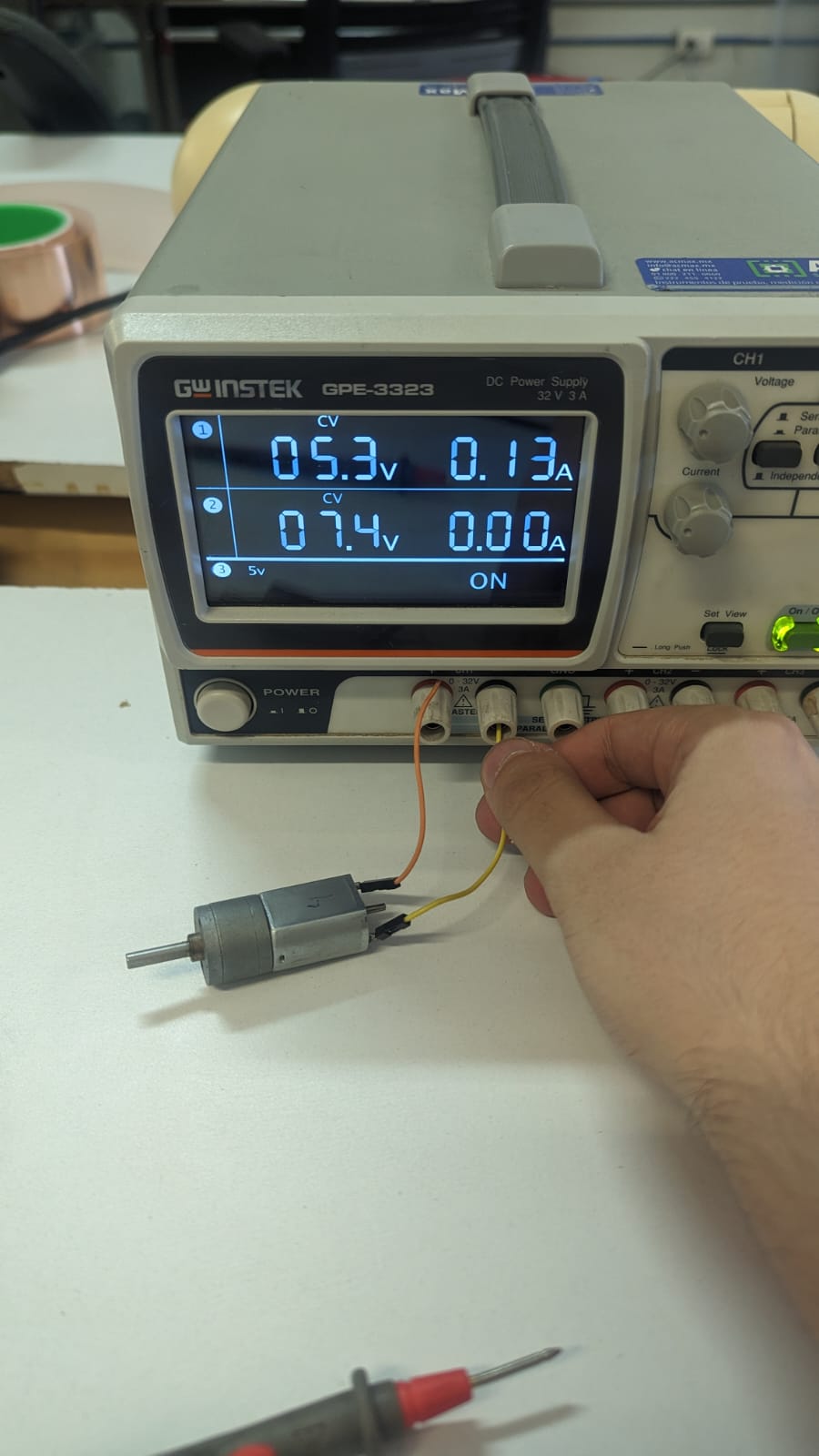
To measure the power of our first motor we wired directly to the banana plugs our DC motor as seen below. Where we can see that with a 5.3V supply we have a 0.13 Amp current which according to out diagram we could calculate the power with the following formula:
\( P = VI \)
\( P = 5.3V*0.13A = 0.689 W \)
As a second measurement of power we used our multimeter. We need to wire in series the multimeter to the circuit taking into account the max current we can measure in our case is 10 Amps . We can see an example of this type of wiring in the following image.

We took two measurements with the multimeter, the first one was the current being measured when the motor was stable and the second we configured the multimeter to get the max value measured, which sould be our peak. Lookin at both measurements we can see that a non stall movement in the DC motor has a current of 0.126 Amps similar to the one measured bye the power supply and a peak current of 0.351 Amps which would give a peak power consumption of:
\( P = 5.3V*0.351A = 1.86 W \)


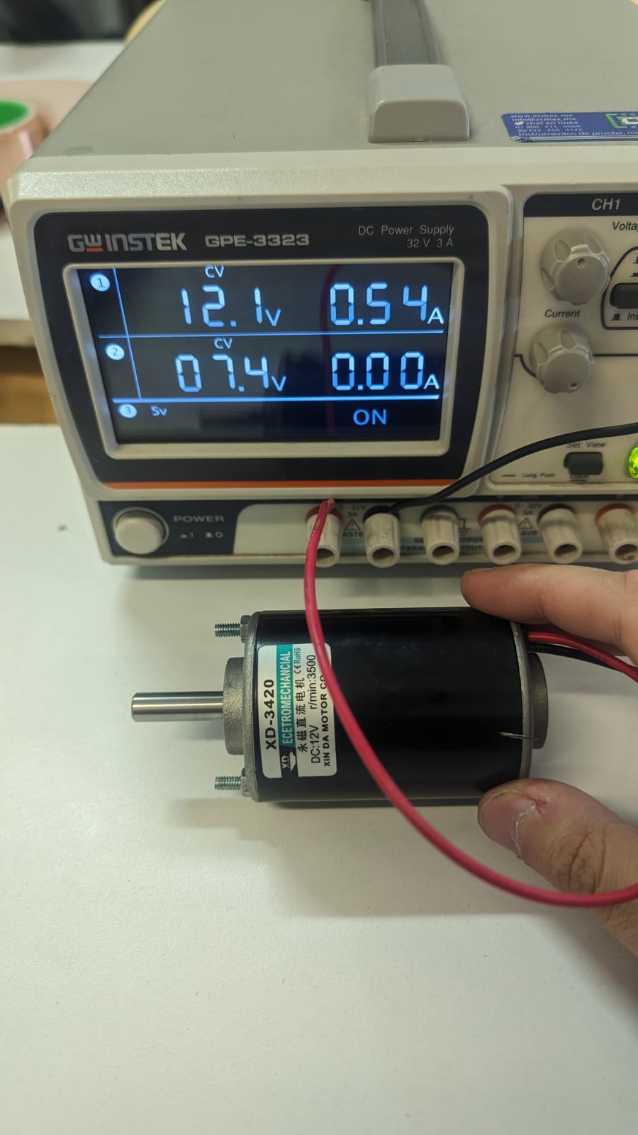
Next we tested our big DC motor, the handson. Where we repeated the steps done. Starting with the power supply, where with a 12.1 V supply we get a 0.54 Amp current use. Which would mean that \( P = 12.1V*0.54A = 6.534 W \)
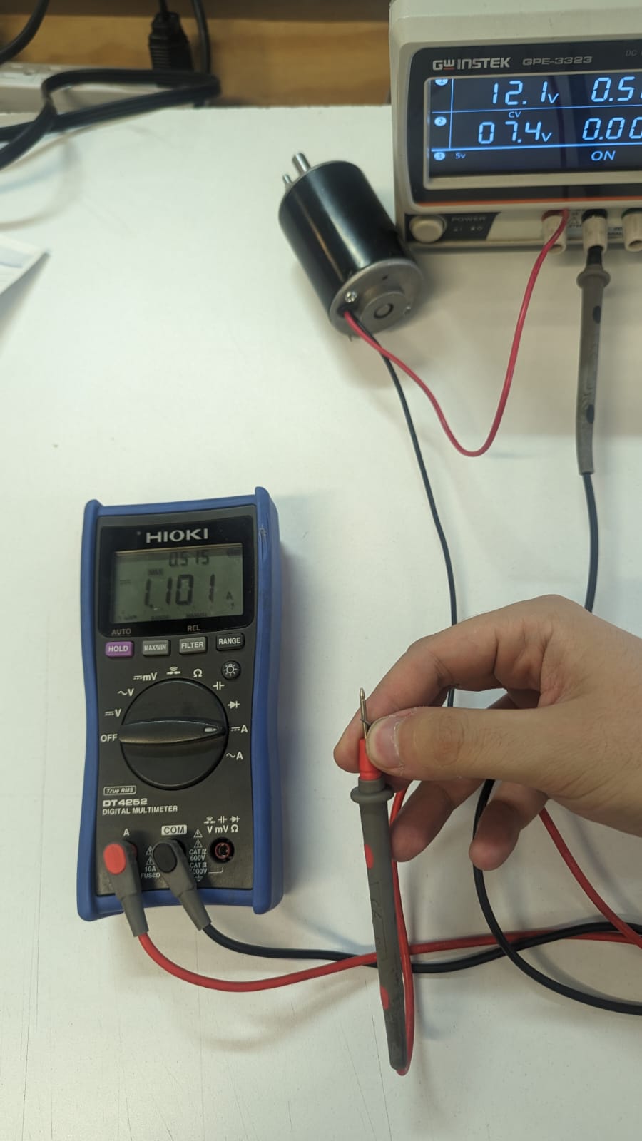
In our multimeter test we again tested both peak, nominal and average current measured at the same 12.1 V supply. Which gave us three different current measures
A nominal 0.492 Amps where the motor not stalling was being used
\( P = 12.1V*0.492A = 5.953 W \)
A Max current of 1.101 Amps for the motor
\( P = 12.1V*1.101A = 13.322 W \)
An average current of 0.515 Amps
\( P = 12.1V*0.515A = 6.2315 W \)
Which would mean that we should try and use a driver which can stand at least the peaks of our motors.

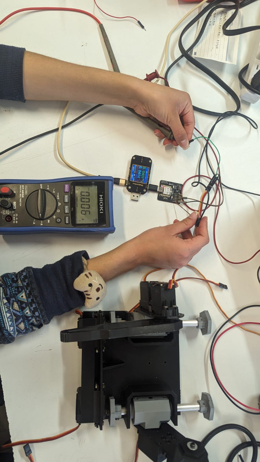
The last device we are using is our Servo. Here we are using our USB current Voltage checker. Where we programmed a sweep routine seen in the video below and using the following slightly modified code by luis Lamas:
                        #include
                        Servo myservo;  // create servo object to control a servo
                        void setup() {
                            myservo.attach(28);  // attaches the servo on pin 28/D2 to the servo object
                        }
                        void loop() {
                        // goes from 180 degrees to 0 degrees
                            myservo.write(0);              // tell servo to go to position 0 degrees
                            delay(2000);                   // waits 2000 ms for the servo to reach the position
                        // goes from 0 degrees to 180 degrees
                            myservo.write(180);            // tell servo to go to position 180 degrees
                            delay(2000);                   // waits 2000 ms for the servo to reach the position
                        }
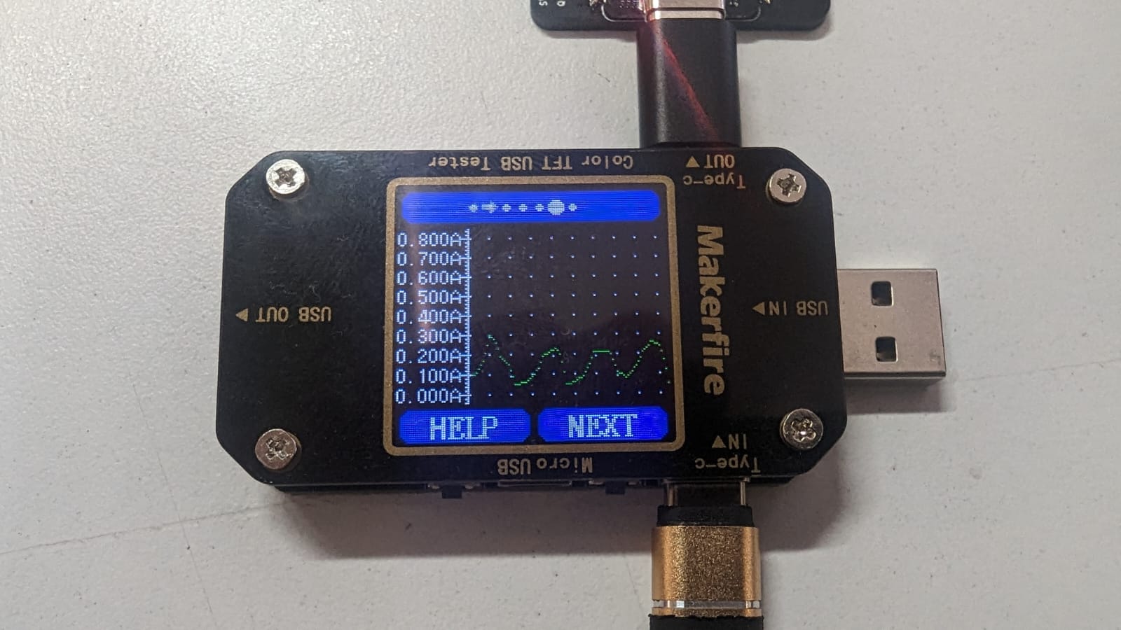
Here we see a graph of the current being used by the servo. We can see how it creates a like a wave shape signal. This is because it creates a peak current at the start of the movement and when it creates an inertia it requires less current to move.
For our second measurement we used the option to measure the mAh which is how much current is needed from a power supply to keep it working 1 hours as well as the mWh

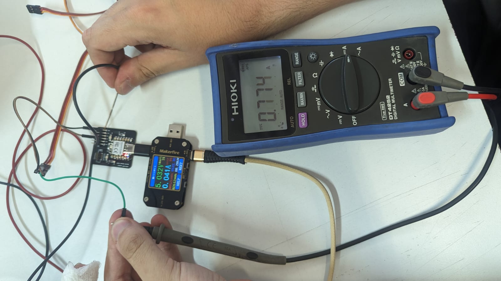
Next we measured the current used by the servo with the multimeter. Where we measured a stand by current of 6 mA when the servo was powered but not moving.
And finally we measured the current when the servo had som force applied to it, which was 0.774 A. Meaning a
\( P = 5V*0.774A = 3.87 W \)