6. Embedded programming
For this week we learned to programm the RP2040 microcontroller on the PCB made on week 4. While learning how to programm it I didn't need to solder new components to the PCB, but I did need it to make the assignment. During this week we learned to programm in C++ with Arduino IDE and in python with MU Editor, which I used to compare while programming this week's task.
Learning the Basics for C++ and Python Programming
I already knew how to programm, but the programming lesson helped me to review some things about it. I also learned new things, such as the things regarding the MU Editor. This assignment has a group page where are all the architectures and MCUs (Microcontroller Units) available in FabLab Puebla. The architectures are AVR (8-bit), ARM Cortex-M0+, RISC-V (32-bit), Xtensa (LX6/LX7), Tensilica L106 (32-bit), and ARM Cortex-M4F. The MCUs are ATTiny45/85, ATTiny44/84, ATTiny412, ATTiny1614, ATmega328P, ATmega32U4, SAMD21, RP2040, ESP32-C3, ESP32-WROOM, ESP32-S3, ESP8266, STM32L432KC, and nRF52840.
Bootloader Mode
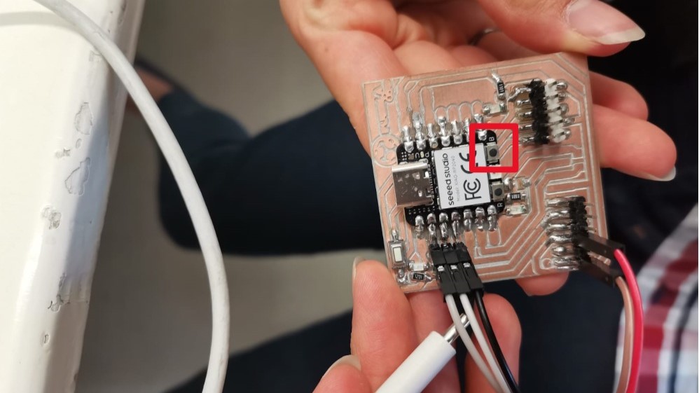
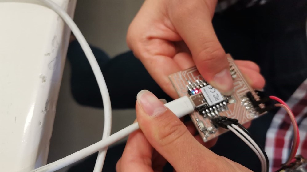
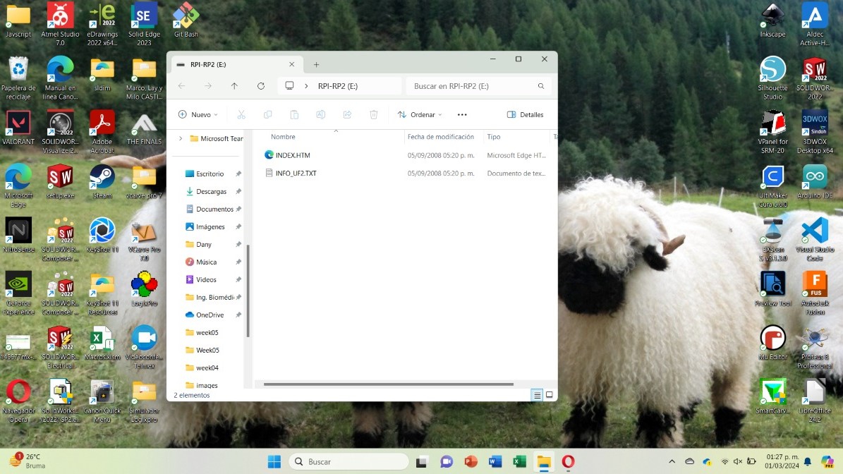
The bootloader mode allows the microcontroller to have new firmware uploaded without the need of having an external programmer. This is a very simple process. I put the RP2040 in bootloader mode by keeping the B button (first picture) clicked while connecting the Xiao to the computer (second picture). If it is indeed in bootloader mode, the RP2040 should pop on the screen (third picture) named "RPI-RP2".
Arduino IDE
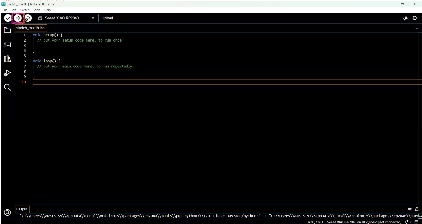
The Arduino Integrated Development Environment (Arduino IDE) is a software that can be downloaded freely and is used to programm on different boards. The interface look like this:
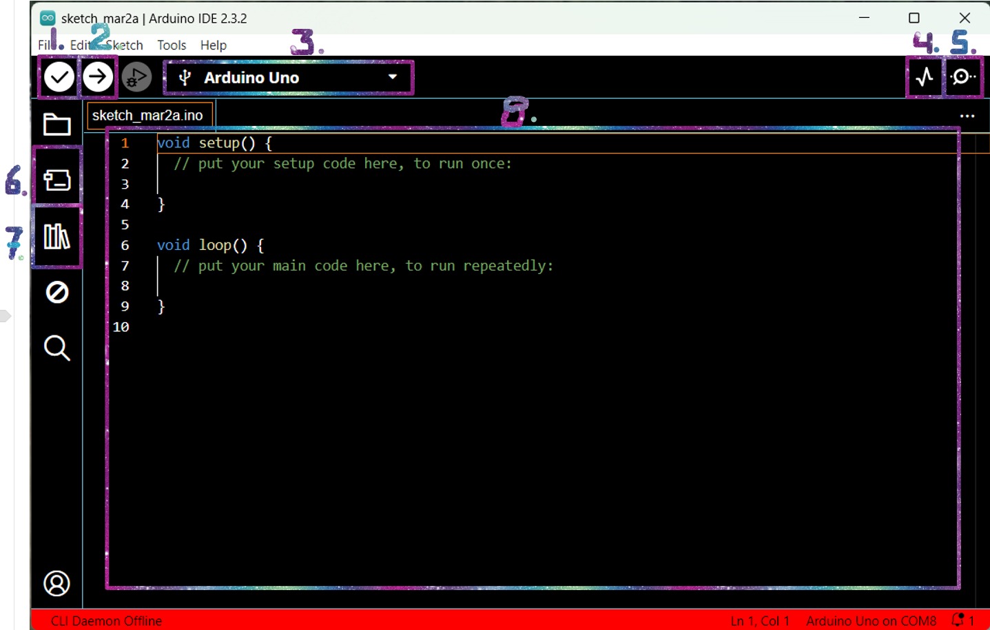
- Verify button: to know if there's something wrong with the code.
- Upload button: to load the code into the microcontroller.
- Boards: there you can select the board and port you are using.
- Serial plotter: to make a graph.
- Serial monitor: to send and receive messages.
- Boards manager: to install or uninstall boards.
- Library manager: to install or uninstall libraries.
Then, to programm it, I followed the next steps:
- Put the RP2040 in bootloader mode.
- Opened a new sketch in Arduino IDE.
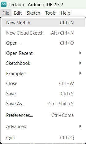
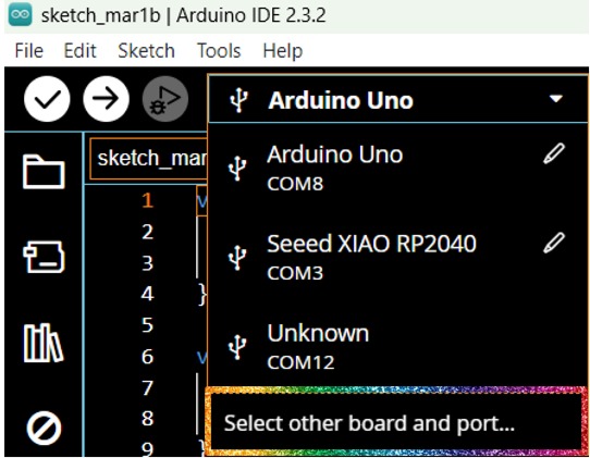
- Clicked on the "Arduino Uno" that I had from a previous work and went to "Select other board and port…".
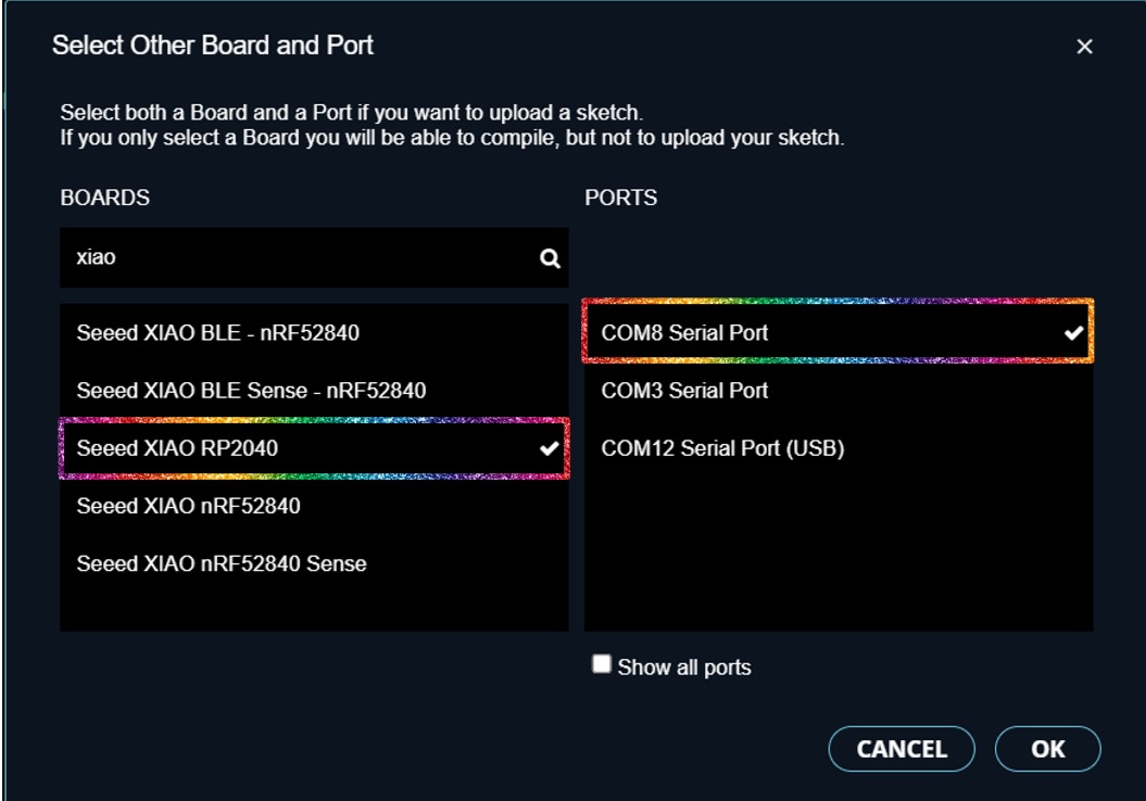
- Selected the "Seeed XIAO RP2040" and the "COM8 Serial Port".
- Uploaded the code with the upload button.
Mu Editor
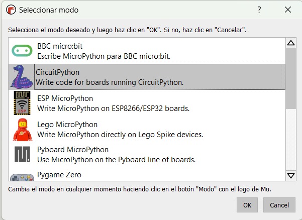
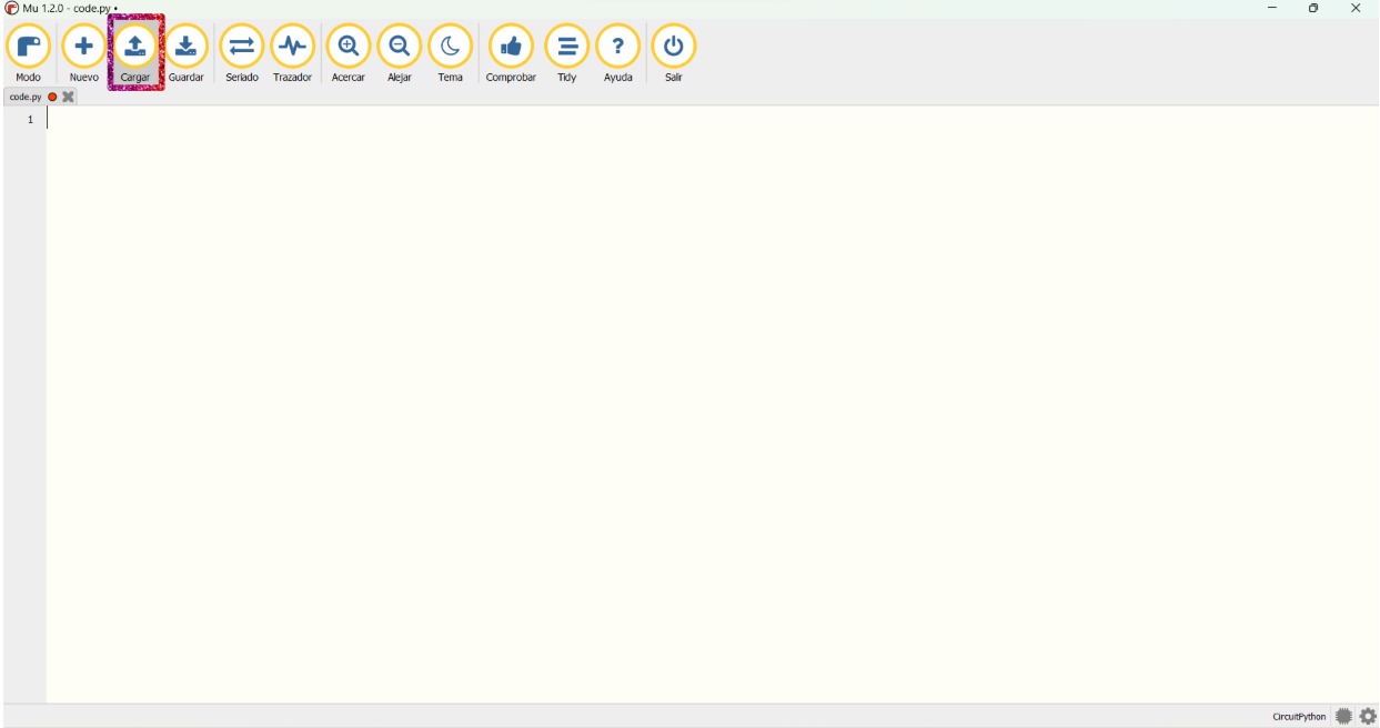
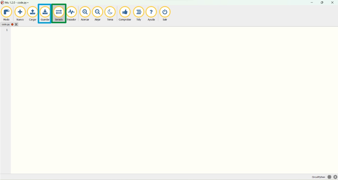
The Mu Editor is also a software that can be downloaded freely and has different modes; this time we were using the CircuitPython mode. The interface look like this:

- Mode: select one to define how is it going to work.
- New: to create a new file.
- Upload: to load the code to the microcontroller.
- Save: to save the code into the microcontroller.
- Serial monitor: to send and receive messages.
- Serial plotter: to make a graph.
- Workspace: space to write the code.
To programm it, I followed the next steps:
- Put the Xiao in bootloader mode.
- Made sure that the mode is "Circuit Python".
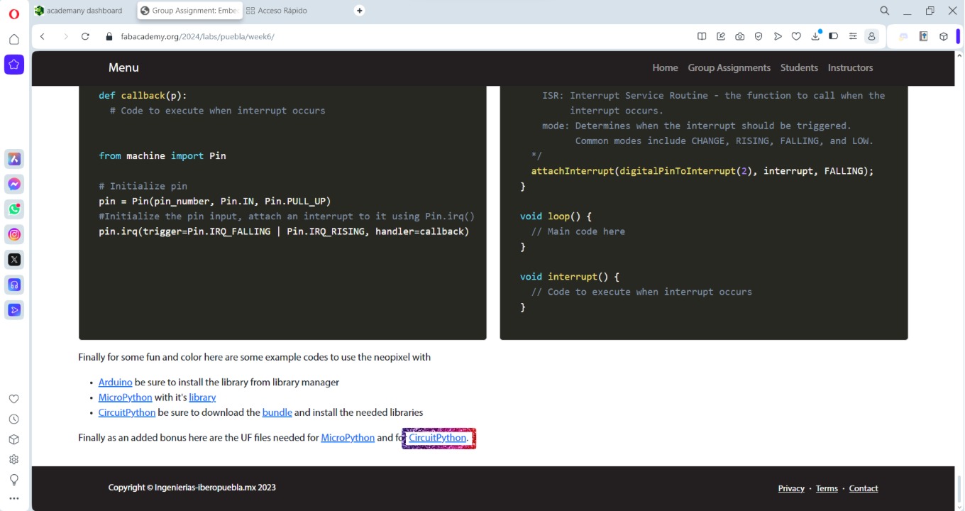
- Downloaded the "CircuitPython" file from the group page to let the RP2040 to be programmed with python.
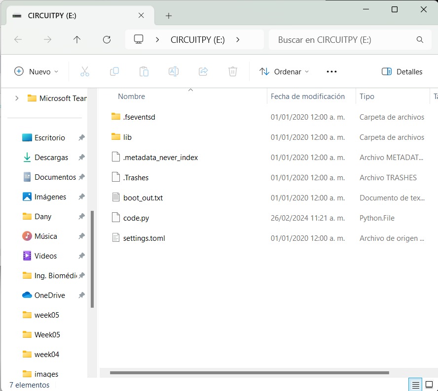
- Dragged the file to the RPI-RP2 to look that way:
- Clicked on "Load".
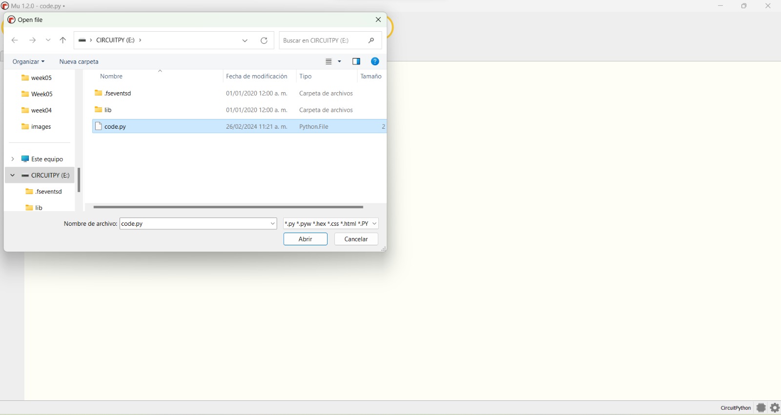
- Selected the "code.py" file.
- Clicked on "Serial" (green rectangle) to verify communication while programming.
- From there on, the only thing to do is click on "Save" (blue rectangle) to load the code into the RP2040 each time there are changes.
Examples
During the practices I only experimented with python (MU Editor), because I have already worked with C++ (Arduino IDE and Visual Studio Code). So here are some examples I did with it:
- Turn on and off a LED:
- Turn on a LED while clicking a button.
- Turn on the LED neopixel already present in the RP2040 using the color wheel. For this I copied the Adafruit and the neopixel libraries into the "lib" folder of the CIRCUITPY.
Solder New Components
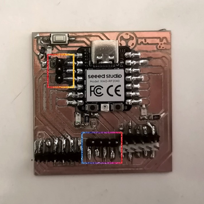
For this week's task I wanted to control the neopixel LED usng potenciometers. There would be 3 potenciometers controling the red, green, and blue part of the RGB colors, so I had to solder new pinheaders to the PCB and solder the VCC and GND of all the potenciometers.
I needed new pinheaders, because the potenciometers send analogic signals and the only available pinheaders were digital. Also I had to solder pinheaders for the 3V supply. The analogic pinheaders are the one on the left, while the VCC and GND are the ones in the mid-bottom:
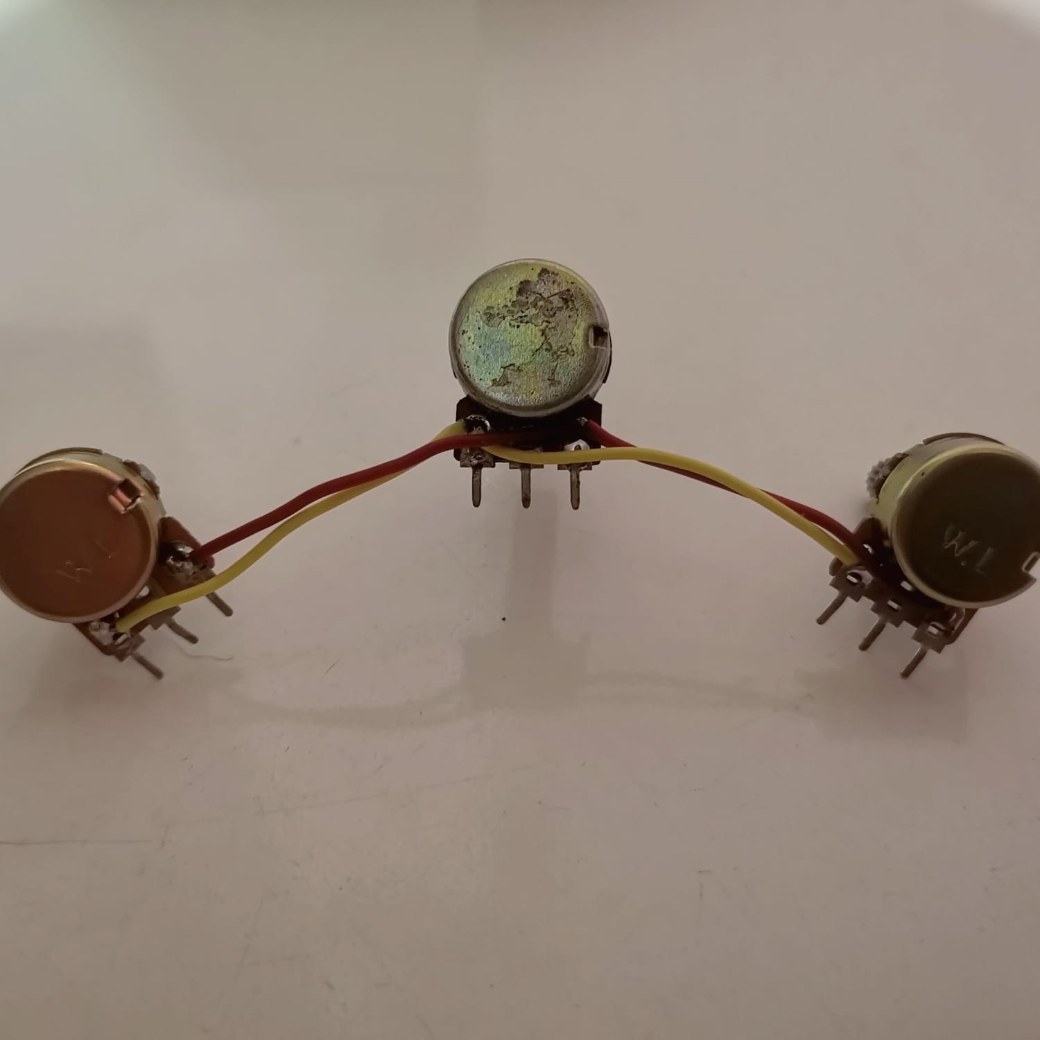
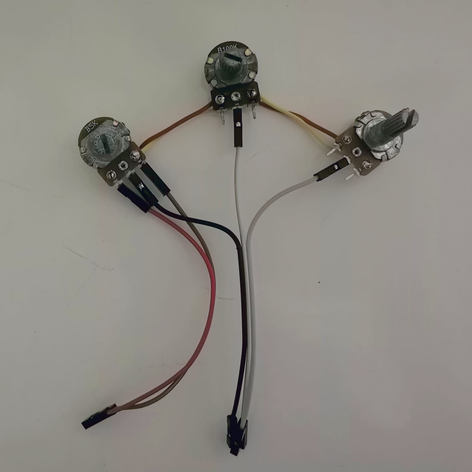
The potenciometers were soldered in this way, soldering the VCCs and the GNDs together (1st picture). Then I only connected the VCC, GND, and the signal pins (2nd picture) to the PCB (3rd picture):

Assignment
The assignment consisted in writting a program that allowed the microcontroller to interact and communicate with devices. I wrote the programm with C++ (Arduino IDE) and with python (Mu Editor). In my case I wanted to use the PWM, because I will be needing it for my final proyect. I wrote a programm that controlled the LED neopixel with 3 potenciometers, where each potenciometer would be controlling the red, green, and blue color. However, these potenciometers would also control the PWM of a red, a green, and a blue LED that were already soldered into the PCB from week 4 (just as if it was fate for me to do this task). The materials I used were the following:
- 3 Potenciometers (5 kΩ).
- 5 jumpers.
- The already made PCB.
Arduino IDE
At first, I wasn't even able to tunr the LED on, and it was beacuse I was calling the wrong pin. But once I could turn it on, everything went easier. The next problem I had was that the colors weren't changing that much, so I used the serial monitor to know which were the values sent by the potenciometers. In conclusion, the potenciometers' values were going up to 1041 (very far from the 255 requiered range), ending in colors changing super fast. To solve this I divided the potenciometers' signals by 4 to work with them. Finally, the code ended like this:
Mu Editor
The main problem with this was that the Mu Editor wasn't able to detect an object of the neopixel library, which was because I used the wrong uf2 (however, in this webpage I linked the correct one). Also there were some problems regarding the delcaration of the LED pins, which I had previously declared in the python code as digital. Finally, the code was as follows: