KiCad
Using KiCad for designing a PCB involves a structured process that begins with the schematic layout.
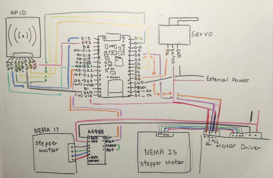
In the schematic editor, I first add all the necessary components and establish their connections based on the circuit design.
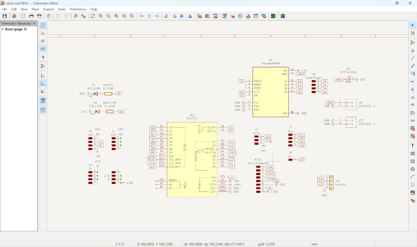
This step is crucial as it defines the electrical connectivity between components and serves as a blueprint for the PCB layout.
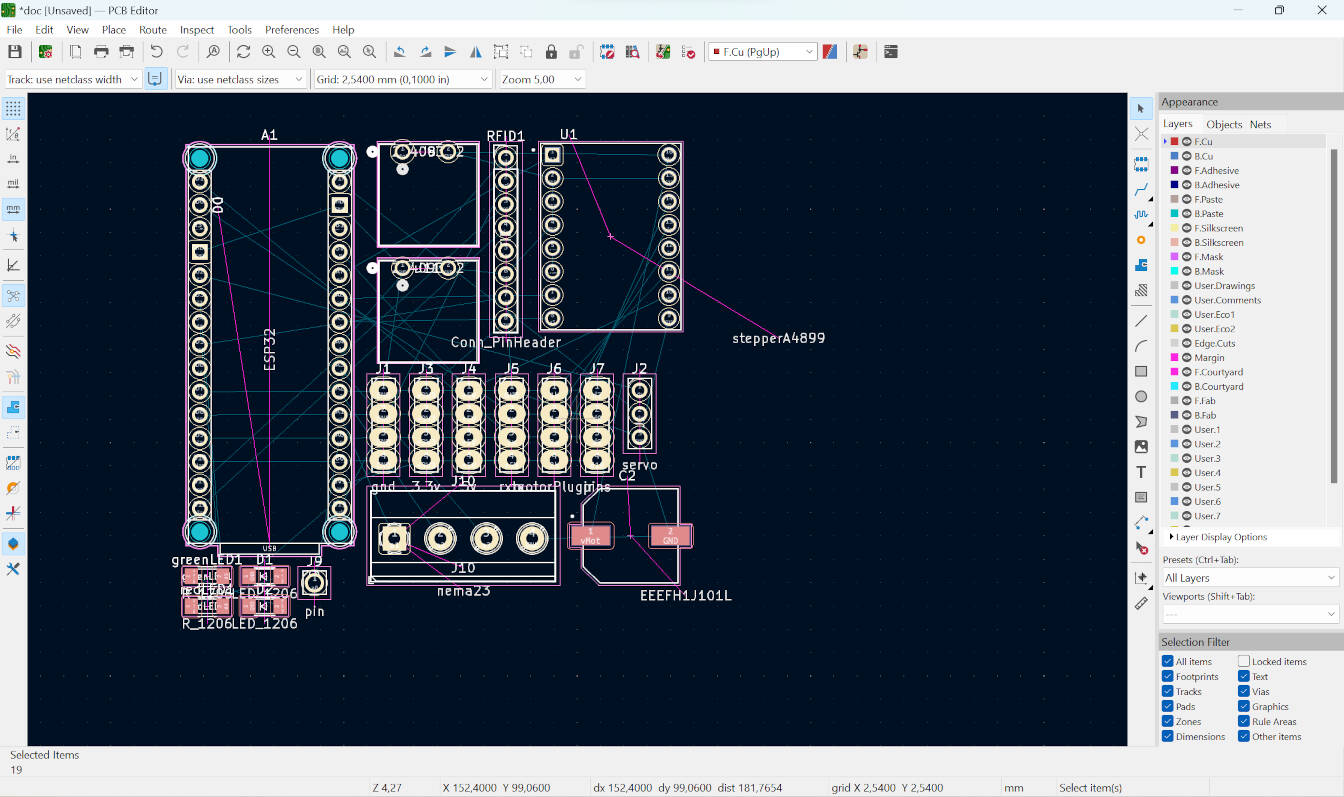
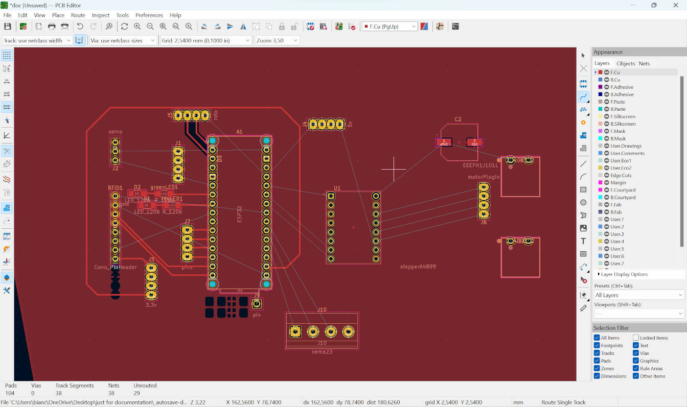
Once the schematic is complete, I transition to the PCB layout editor, where I place the physical footprints of the components onto a virtual board.
Here, I arrange them optimally for space efficiency and signal integrity.
In this part of the design process, I discovered that creating a single-layered PCB would not be practical for my project because certain parts were obstructing the connections of others.

While I could have resolved this issue by using a 0-ohm resistor to jump signals or by creating a physical wire bridge over the connections, these solutions did not align with my goal of achieving a cleaner PCB design.
Fortunately, the milling machine available at our lab, the LPKF, features image recognition technology that greatly simplifies the creation of double-sided or double-layered PCBs. This capability allowed me to design a two-layered PCB, which provided the necessary space and routing flexibility to accommodate all components and their connections without compromise.

CAM processing (Milling)

For this project, I produced a double-sided PCB design, which required additional steps in the machine software during setup.
Firstly, instead of selecting a "SingleSided_top" template I used on the electronics production week, I chose the "DoubleSided_NoTHP" one.
Then, after importing my PCB files and creating the isolation, this process remains the same as the one for the single-sided PCB from the production week.
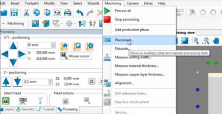
After the isolation process, there is an additional step to create fiducials, but before this, I have to define the placement of the board and material.
This is done by going to "machining" then "placement" and choosing the material and design location for milling.
.jpg)
Then go to "machining" and "fiducials".
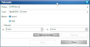
On the pop-up screen, pick two to three areas on the copper material but outside your milling zone.
In my case, I chose three points, and this meant that the machine drilled three holes to help with the alignment of the second side of the board.
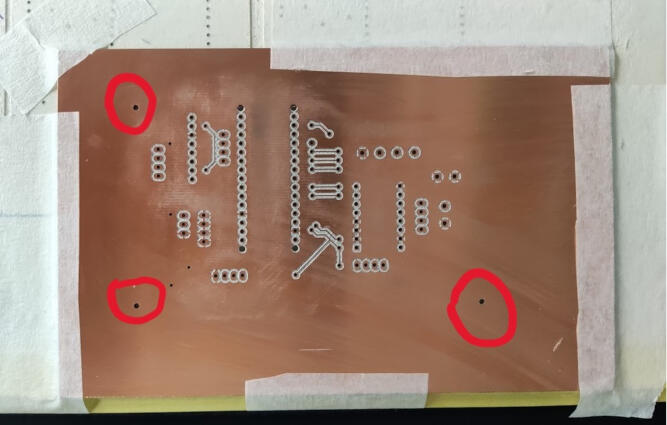
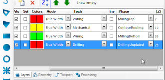
After finishing this, it's business as usual, and you can create the wizard and mill the board. The first part to be milled was the bottom layer, and as you can see, the three holes around the bottom layer are the fiducials.

After the bottom layer is milled, on the software there are instructions for flipping the board. During this, it's important to try to align it as best as possible for the image recognition to work properly and find the fiducials. After this, the top layer can be milled and you're done.
Soldering
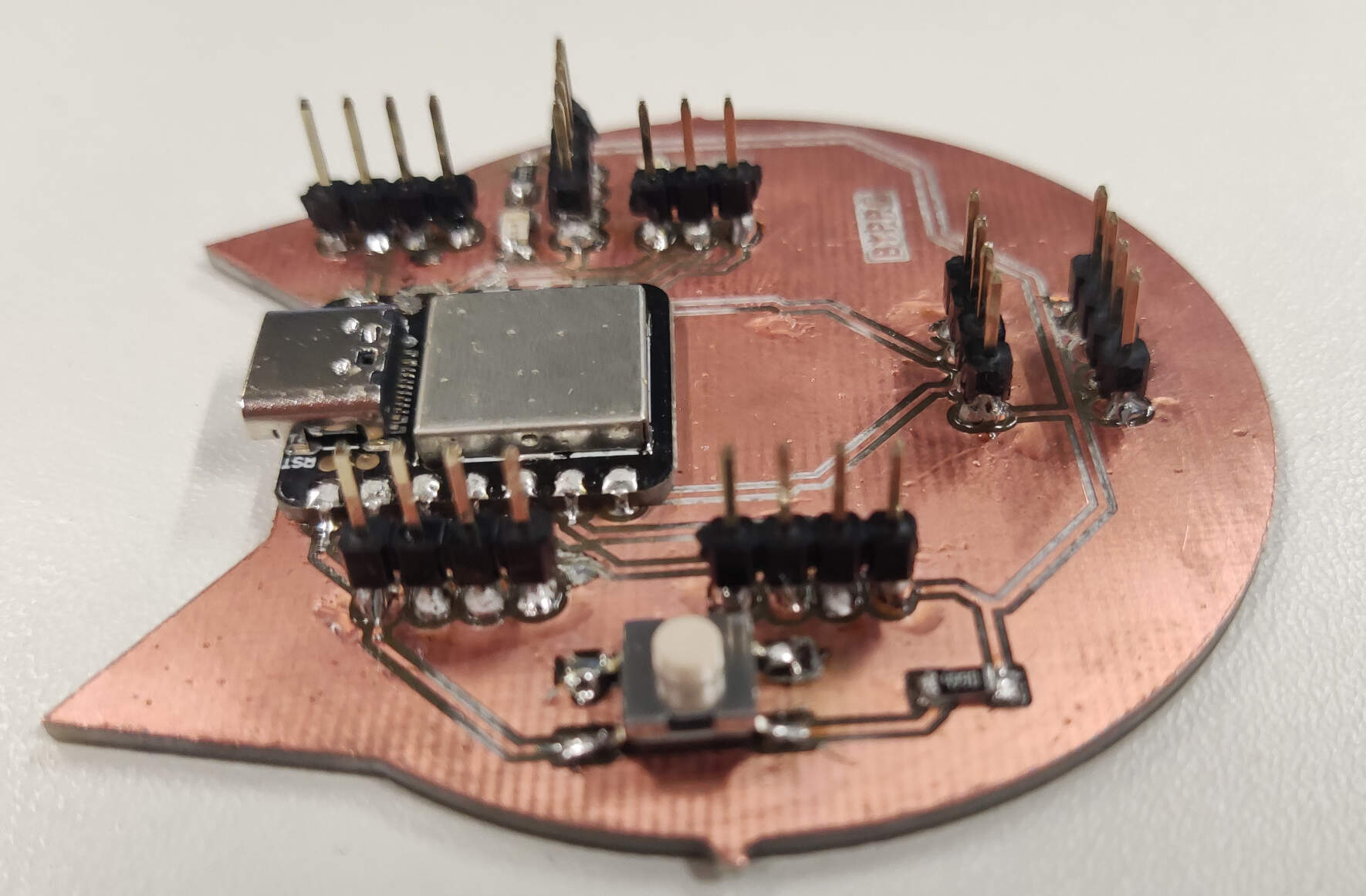
With my board milled, all that was left was to solder all of the necessary components to it and test it.
The soldering setup and process were explained here.
Although this new PCB was much more challenging to solder than the first one, the components list is as follows:
Components List
Before starting to solder I first added all of the rivets, to do this, I used a tin twezer and inserted the rivet in one of the ends of the tweser, this allowed me to insert the rivets with more ease, as the holes are a tight fit, after inserting them half way i removed the tweezers, and pressed it down untill it was compleatly in, then i used a press to finish the job.
The small tip of the rivet press we have in the lab was broken. This tip is used to help align the rivets, making it a very helpful tool for achieving nice results with your riveting.
However, the new part we ordered was going to take a little while to arrive. Despite this, I decided to proceed without it, as it is still very much possible to use the press without the alignment tool.
Since it was also my first time using this tool, some rivets came out a bit funky, and I wasn’t sure if they would work.
This led me to test all of them with a multimeter, specifically on the beeping setting, to check if the circuits were interrupted or not.
The conclusion of this test, you may ask? They worked! Even the funky, questionable ones.
In some cases, for circuits that will sustain a lot of movement and vibrations, you can also solder the rivets on both sides.
However, I did not do so for this board, as it is not the final version.
It’s just the first generation, and soldering all of the rivets is not necessary, especially if they all work.

After all the rivets were in, before starting to solder I placed the components where they should go and observed the difficulty and accessibility for soldering each one.
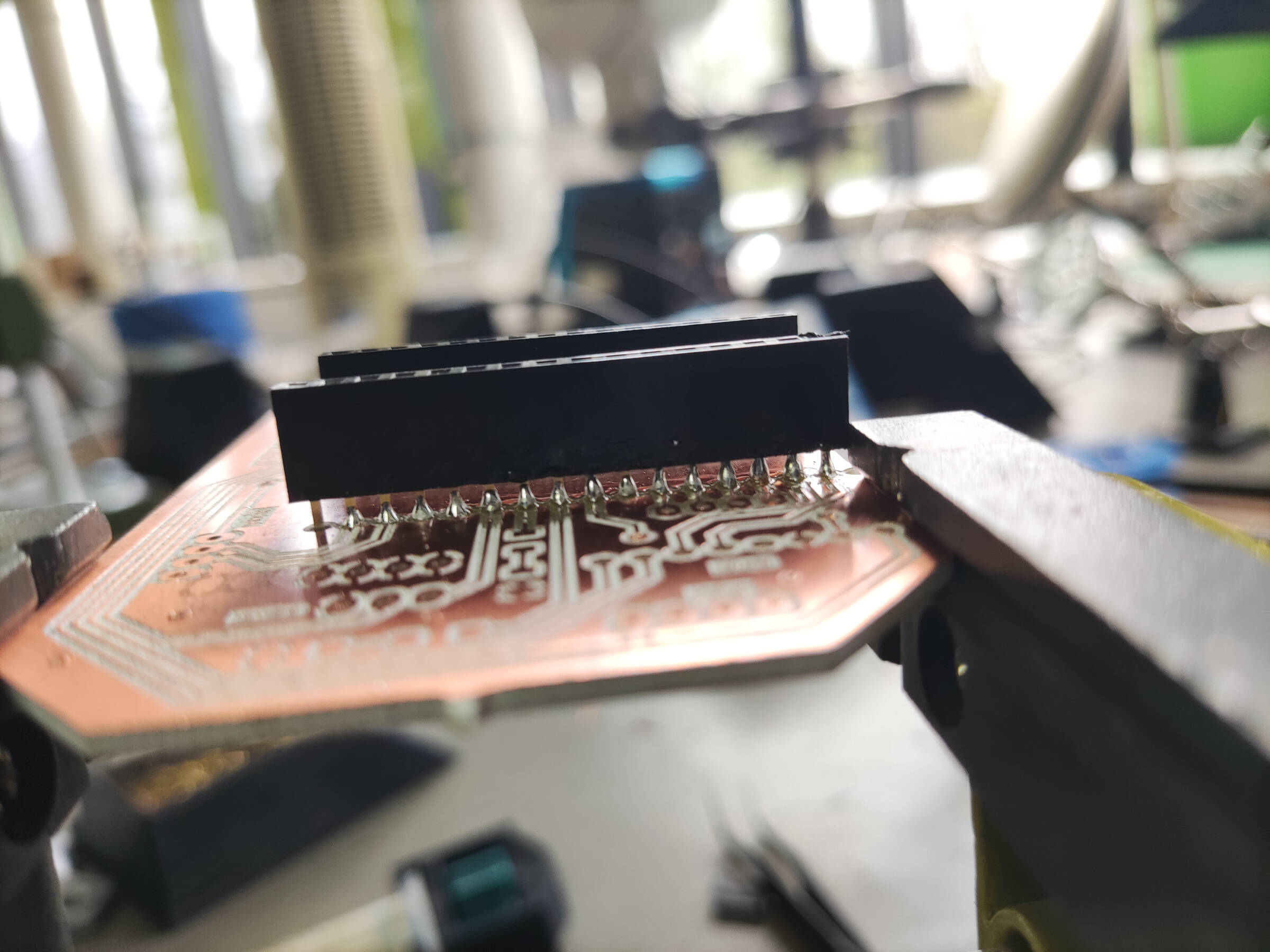
I concluded that I should start from the middle and branch out. This meant starting with the most challenging and time-consuming part: the 1x011 female pin headers.
This was challenging because of the amount and proximity of pins to solder properly and avoid bridges.
To start, my instructor showed me how it was done on a few of the pins, and I carried on from there.
As I was soldering, I noticed some things I could change to improve the board.
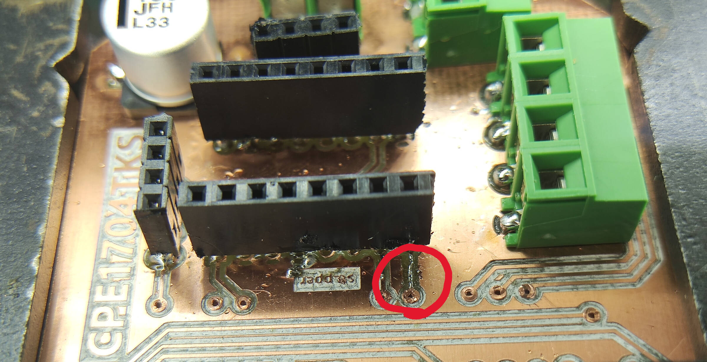
For example, the pads for the pin headers for the stepper controller were very small.
Because of this, there were some problems, such as one of the pads breaking off from its connection.
To fix this, I soldered them together, being careful not to create a bridge.
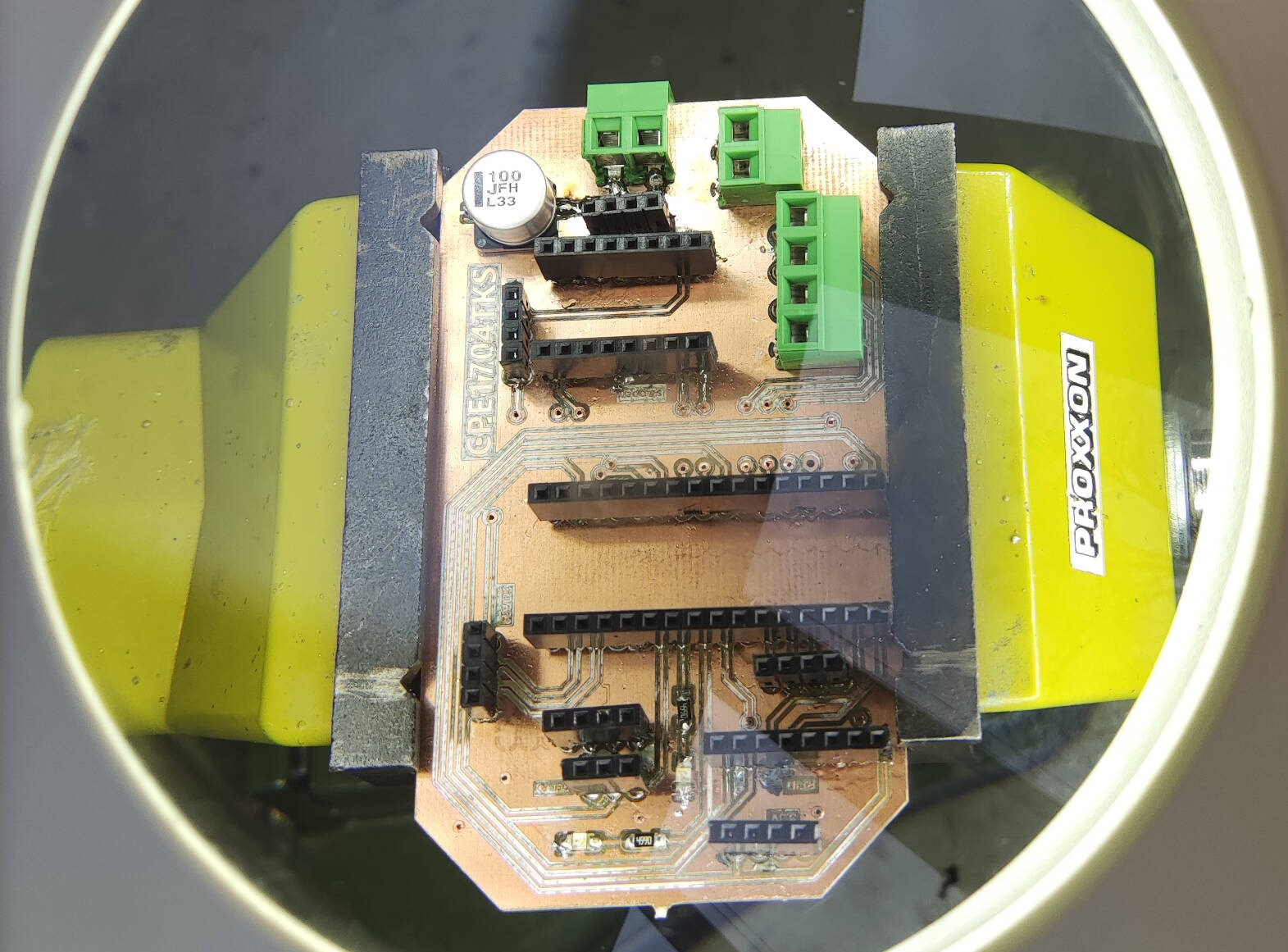
Testing
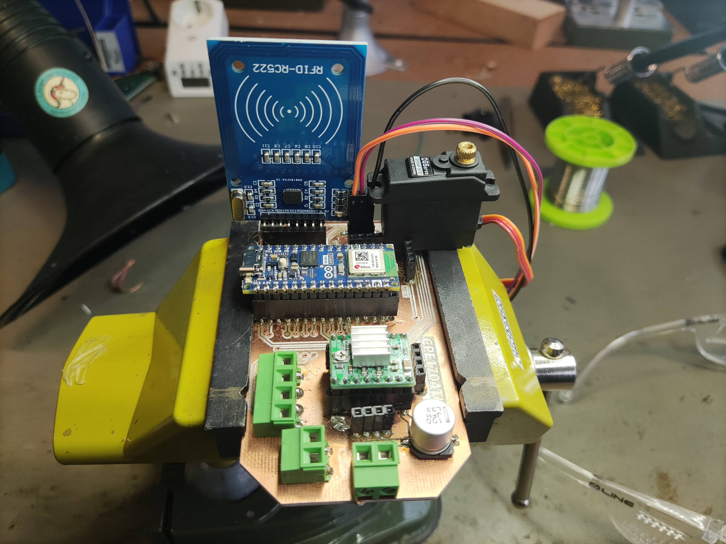
With the PCB finished, it was time to test it.
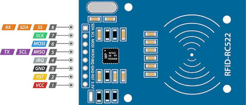
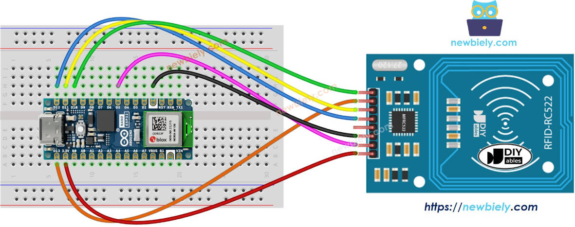
The first part I tested was the connections for the RFID module.
This was very straightforward. I plugged it into the female connectors on the board and connected the board to my laptop.
From there, I used a code I wrote for the RFID module, which you can find in the inputs week.
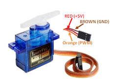
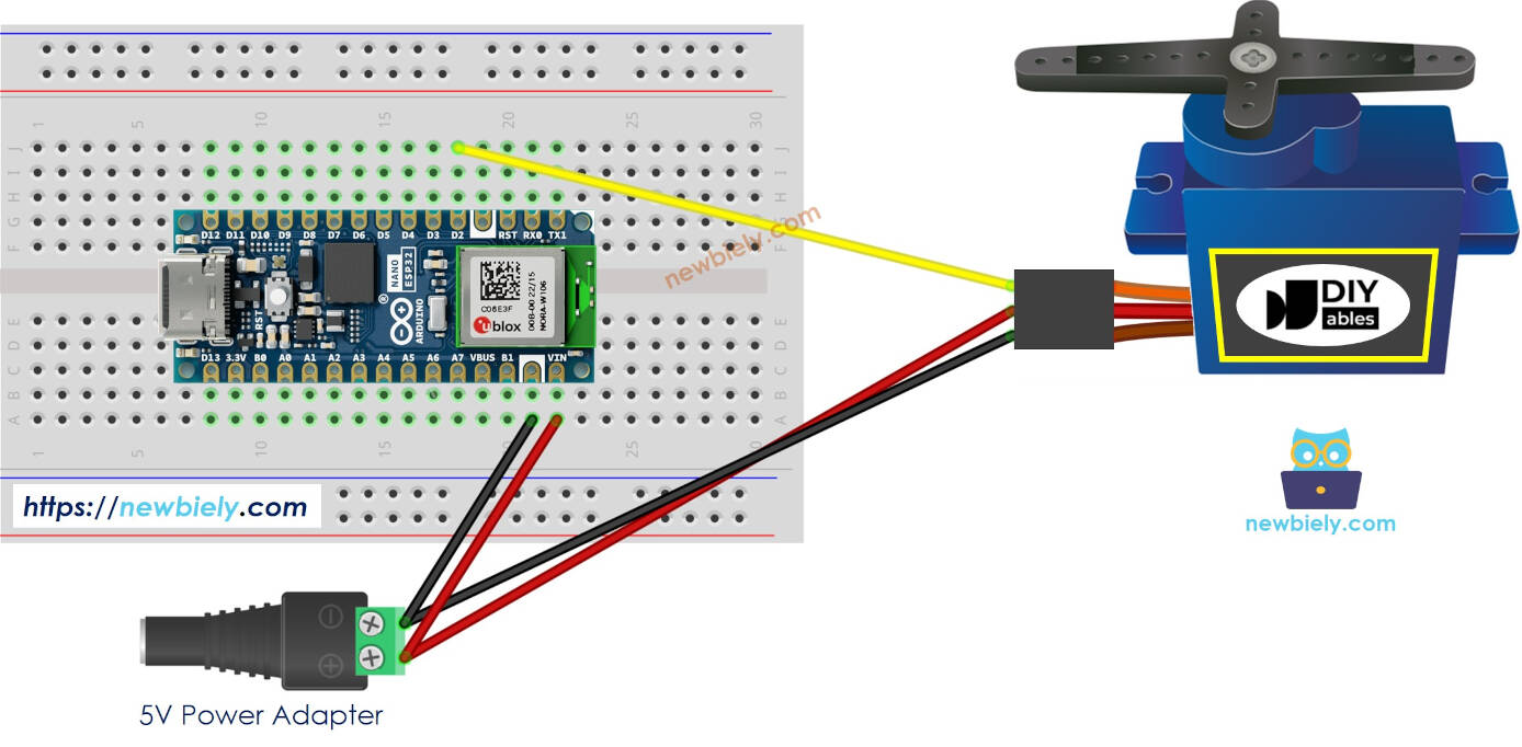
The next part was to test the stepper driver and motors, pluged in the driver to the board, connected two wires to the bloc terminal to an external power source, and connected the stepper motor to the driver.
I then used a code I wrote for the stepper motor, which you can find in the output devices week.
However, there seemed to be a problem, and the motor was not moving.
It wasn't even activated, and I could move it with my hand. This prompted me to test all of the connections with a multimeter.
I would run the code and check if, when the motor should be running, there was a change in voltage in the pins that should be connected to the motor.
There was. However, when I tested the step pin, it was constantly 5V, which shouldn't be happening.
Turns out, the problem was during the design process. I had connected the sleep pin to dir, when sleep should have been connected to reset.
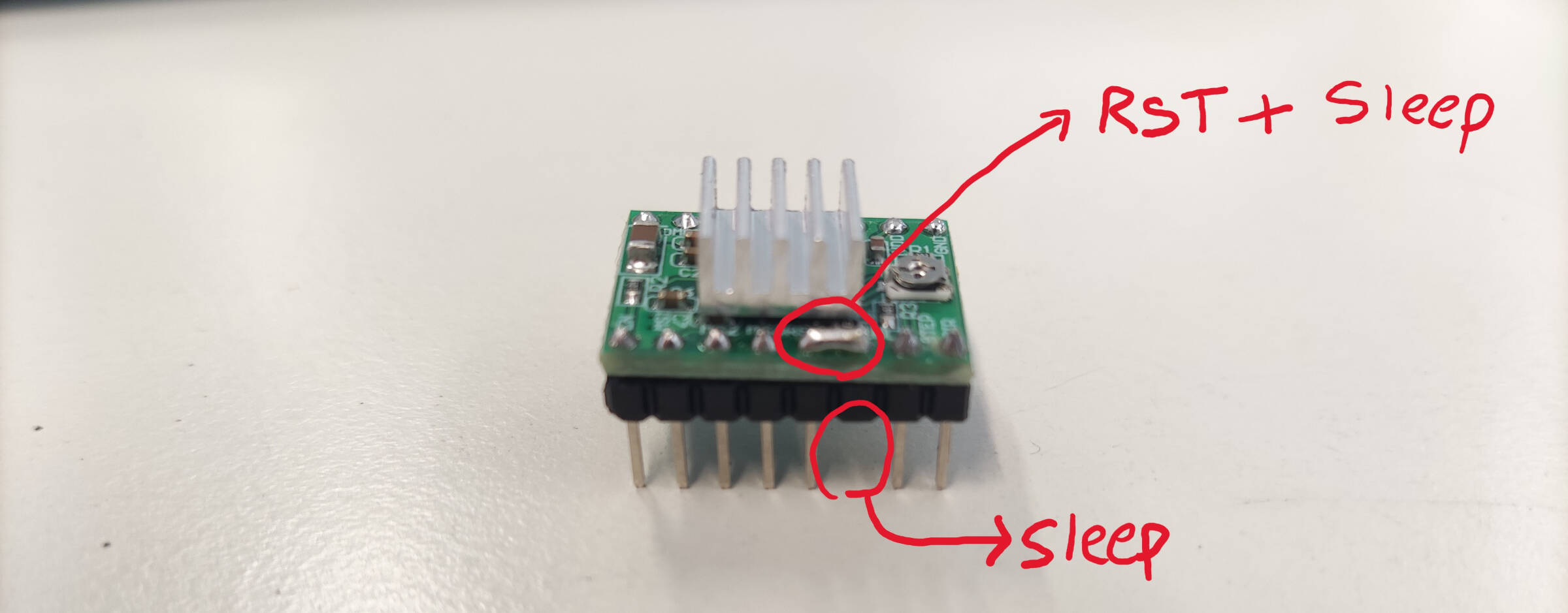
To correct this, I broke off the sleep pin on the driver and oversoldered it to the reset pin to connect them together.
Then, I plugged the driver back into the board and tested it again. This time, it worked perfectly.