Computer controlled cutting
Group assignment
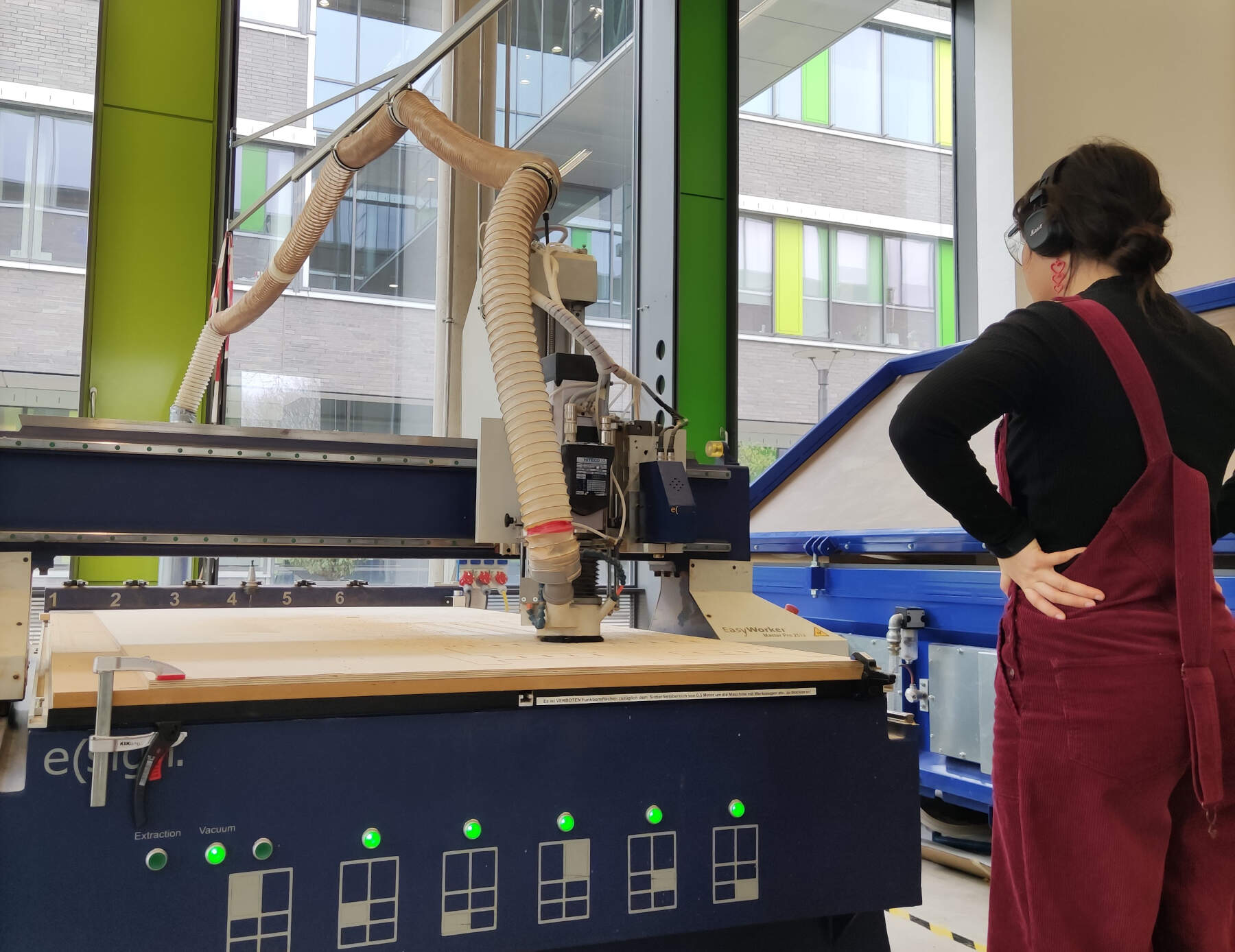
ABOUT OUR MACHINE
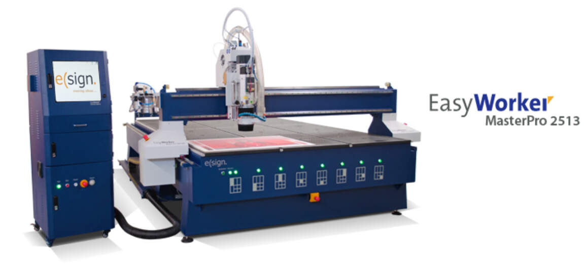
The big CNC in our lab is the "eLsign EasyWorker MasterPro 2513".
The technical data for the CNC is as follows:
- The machine has a working area of 2500mm x 1300mm x 200mm.
- The machine operates at a speed of up to 19,000mm/min, ensuring swift movement and processing.
- Precision linear guidance is utilized for accurate and smooth guidance.
- In terms of data formats, the machinery is compatible with G-Code and HPGL.
- Last but not least, the power supply requirements are versatile, accommodating either 3 Phases or 1 Phase with a voltage of 400V or 230V.
Additional modifications:
- an extension to the vacuum/ dust collection system plus the structure mounted to hold up the tube, plus the actual vacuum
- Automatic tool exchange
Here is a link to the group assignment page.
Individual Assignments:
Computer-controlled machining, commonly known as CNC (Computer Numerical Control) the automated control of machining tools by means of a computer.
A CNC machine processes a piece of material (metal, plastic, wood, ceramic, or composite) to meet specifications by following a coded programmed instruction and without a manual operator.
The CNC machine reads the G-code and M-code instructions and then operates the machine accordingly.
The G-code is a language that tells the machine what to do, and the M-code tells the machine how to do it.
The CNC machine can perform a wide range of operations, such as milling, turning, drilling, and grinding.
I am a bit familiar with using the cnc machine, I have used it before on previous projects,
like a skateboard mold (I got the file from an open source skate board website called skatecad)
out of insulation foam boards that I later cast with concrete to make the final mold, and also boxes and other simppler things,
but so far none of those projects were either compleatly designed by me, or complex enough with press fit joints.
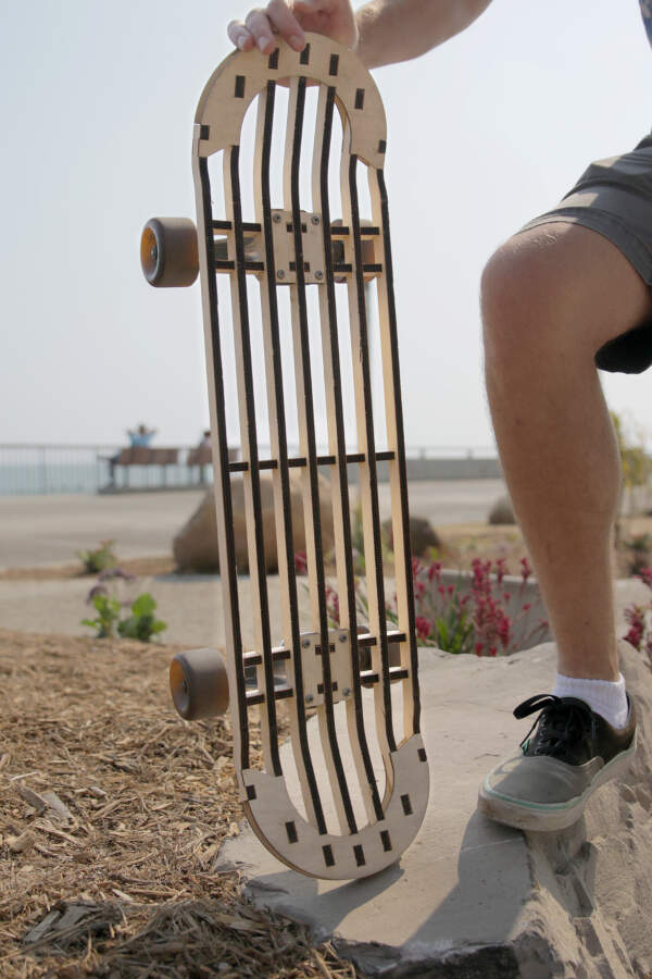
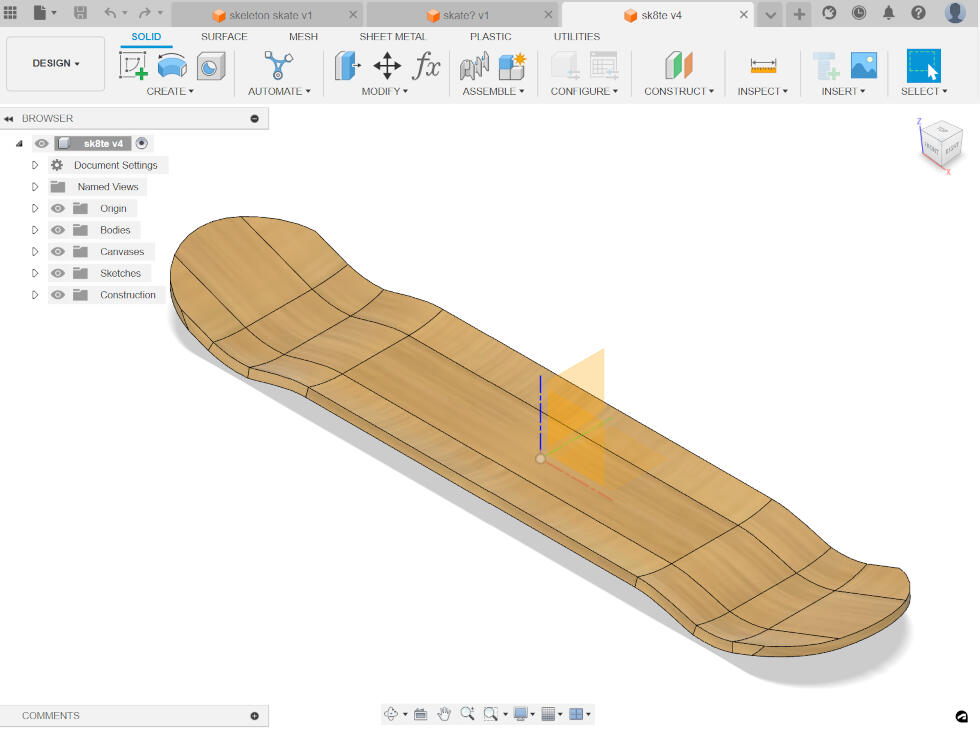
So, originally for this week’s assignment, I wanted to design my own skateboard.
I was inspired by one of William Osman’s videos, where he laser-cut a skateboard that was assembled with press-fit joints.
However, designing something like this proved more challenging than I thought

so I backtracked on this idea and tried to just design a normal board and also a mold for it.
With the idea to cut the mold out of foam and use the vacuum forming machine we have at the lab to shape some layered wooden veneers that I would later shape the board with the contour of the board design.
I did end up finishing this design; however, this whole process would take a lot of time, and since we only have one big CNC at the lab, it would have been hard to manage my time without hogging the machine.

After some thought, I looked around my room and remembered something that always peeved me.
When I come through the door to enter my room, I always take off my shoes, but sometimes I wear boots, and to unlace or relace them, I prefer to sit down.
This forces me to walk to either my desk chair or my bed, which is a bit of a hassle.
Worst of all, I have to walk into the rest of the room with my street shoes on, which always makes me cringe a little, and then later on, I have to clean the floor.
So, I decided to make a shoe rack that sits by my door, where I can sit on and store and organize my shoes.

First, I sketched up some ideas and also looked through Pinterest for inspiration.
Then, later on, I started to design it in Fusion 360.
I also watched a video on YouTube so that I could get a better understanding of how to design a press-fit joint and just the whole structure in a better, more efficient way
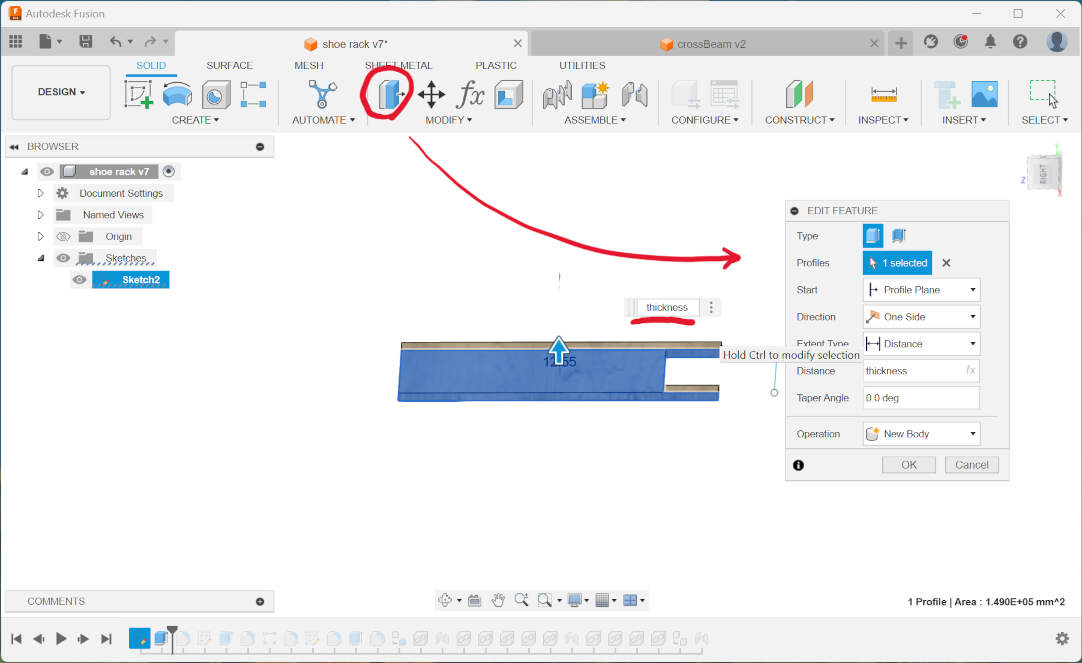
Before even starting to design anything in Fusion 360, I first set some parameters for the design so that I could change certain parts later,
like the thickness of the material, which would be how much I should extrude the sketch.
Creating a parameter for this was crucial for the press-fit joint to be perfect, and also because at the time I was designing,
I wasn’t sure of the material thickness yet, so I knew I would have to change that in the near future.
I also created other parameters for the length, the crossbeam, and what i called plyW (the width of the plywood) and plyH (the height of the plywood) whuch i would use in the manufacturing process.
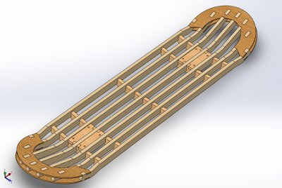
Now, onto the design, I created a sketch of a rectangle on the ZX axis; this will be the side panels of the shoe rack, and I extruded it.
I also created some fillets around the corners.
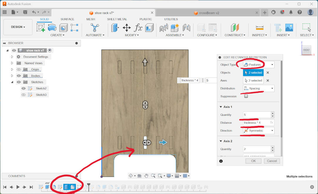
Then, to create the slots for the press-fit joints, I first sketched a small center rectangle,
with the width being the parameter I had set previously, “thickness,” and the height being the parameter “crossbeam.”
Then, I extruded this rectangle and added fillets to it.
and extruded with the parameter “thickness” and the option of “cut.” I also added fillets to this for aesthetic purposes and to make it easier to insert the plywood.
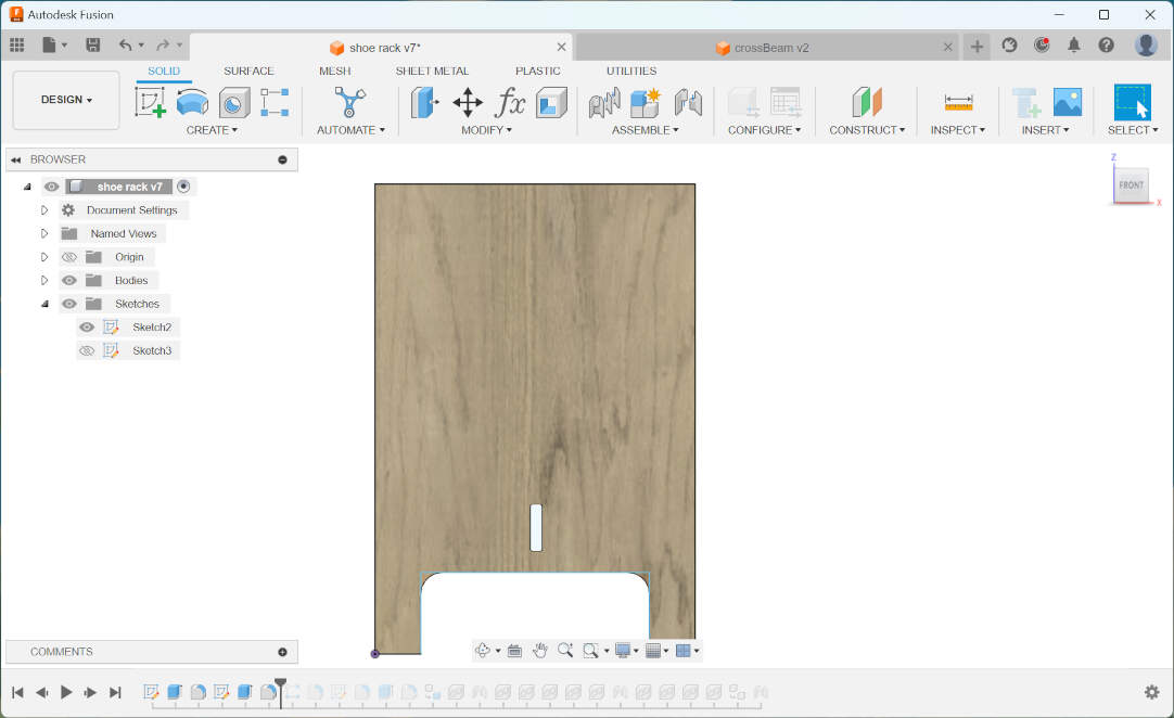
This rectangle sketch was placed in the bottom center of the side panel. To create the rest of the slots, I used the rectangular pattern tool and selected the features of the first slot,
the direction as symmetrical, and the distance between the slots as a function “thickness*4.” To create the top slots, I chose the Z axis and did the same thing as the bottom slots.
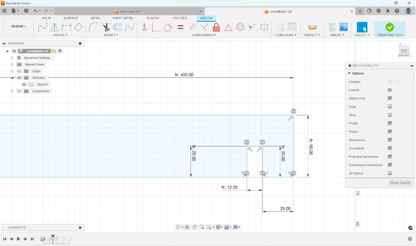

The next step was to create the crossbeam, which would hold the side panels together.
I started out by creating a new sketch, with the first vertical line measuring the parameter “crossbeam,” and another horizontal line 25mm.
The next vertical line was half “crossbeam,” so that’s 25mm (this is to help the fitting process), and the process went on like that.
For the final horizontal line, which determines the length (I wanted the rack to be about 840mm long), I made this line half of that so that I could just mirror the whole thing and have the other half of the rack.
After I finished the sketch, I extruded it and added fillets to the corners.
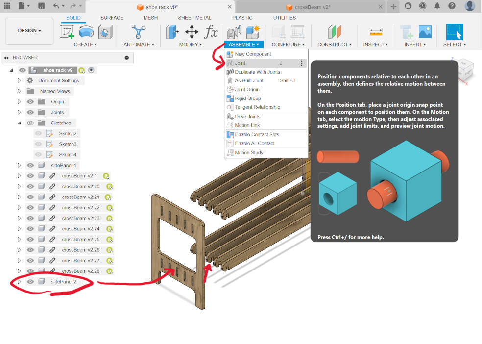
At this point, the crossbeam was a body in the design, but in the long run, this was not what I wanted,
so I changed it to be a component and then from there, I exported this component as another Fusion file.
Then I imported it again into the design as a construction.
This allowed me to create a rigid joint between the beam and the side panel.
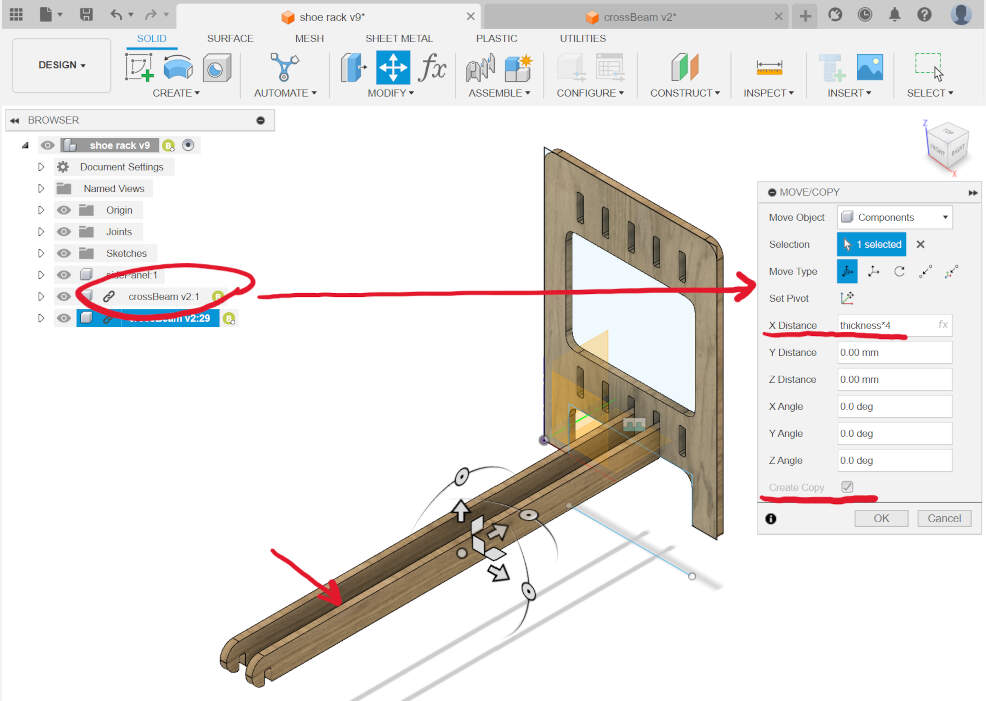
To make the rest of the cross beams, I used the keyboard shortcut “M” for move/copy, and selected the construction.
On the side panel “move/copy,” I checked “create copy” and changed the X to “thickness*4”.
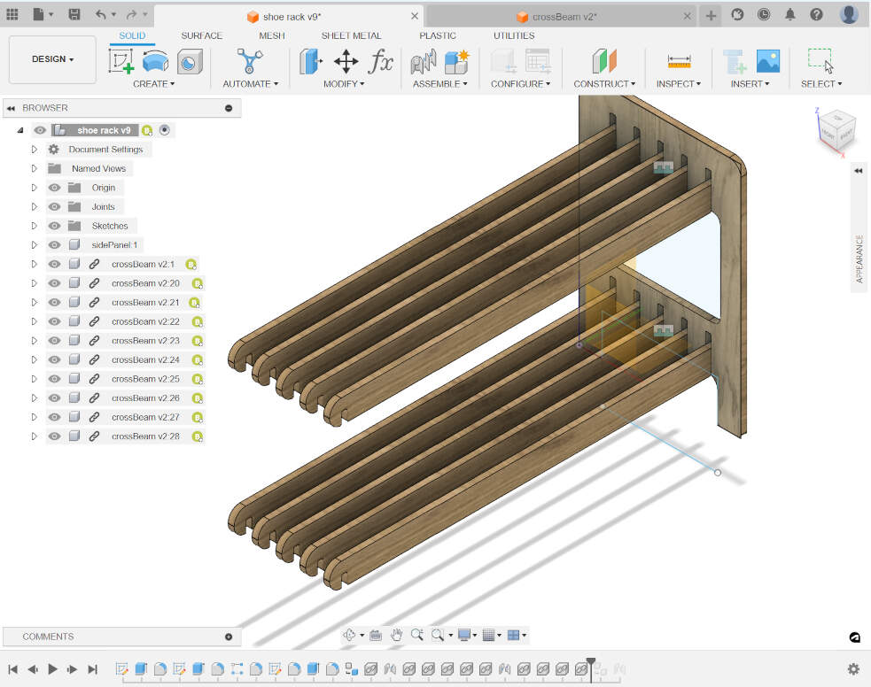
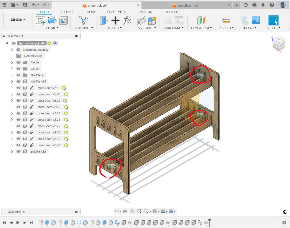
I repeated this process until I had all of the bottom beams in place. For the top ones, I selected the bottom ones and changed the Z so that the copies would be moved up higher to their designated slots.
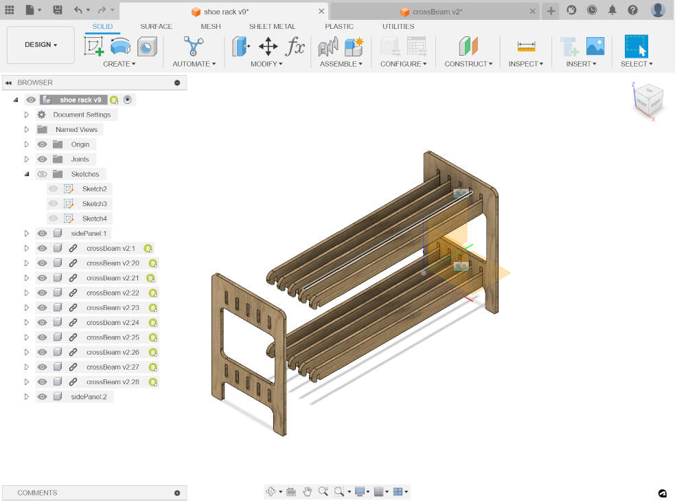
The process for the second side panel was the same;
I selected what I wanted to copy and move, and changed the Y to “length” so that the copy would be moved to the other side of the rack.
I also changed the appearance to bamboo light-semigloss, then selected everything and on “assemble,”
I created a rigid group. This means I could move it around and the parts would stay together.
Manufacture
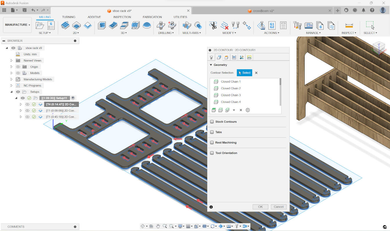
Now that i had my design ready, I had to prepare it for the CNC machine.
this means first nesting all of the parts, which means arranging them flat in a way that they would fit the best in the material,
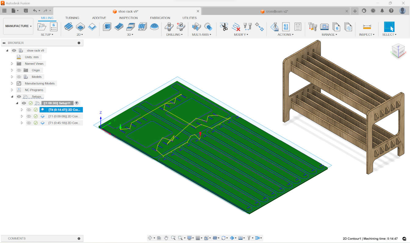
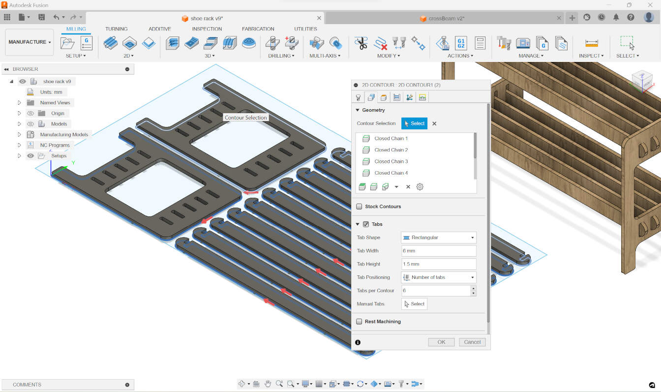
and then generating the toolpaths.
At first, I wasn’t sure how exactly to nest the parts.
I remembered from tutorials of Fusion 360 I had watched before that there was an extension for this, but with further research,
I found that with the new update, there was now an arrange tool, so I didn’t have to download anything external.
To use this tool, I went through these steps:
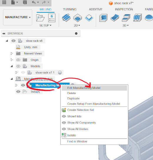
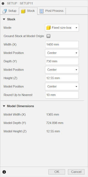
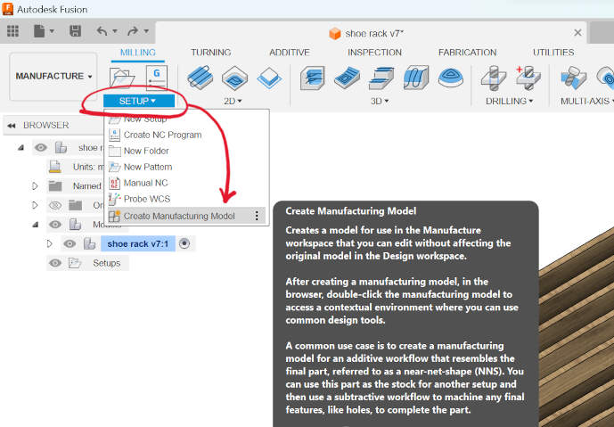
- Create a new manufacturing model in the "Setup" on the top bar.
- Create a new sketch and select the horizontal plane. There, make a sketch of a rectangle that will represent the size of the material you have and will determine how your parts will be arranged, then finish the sketch.
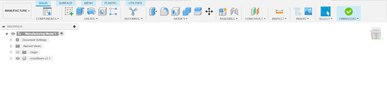
- Right-click on the manufacturing model you just created and click on "Edit Manufacturing Model." This will direct you to a slightly different workspace.
- Then go to "Modify" and click on "Arrange."
- Select the parts you want to arrange and then click on "Envelopes" at the top of the arrange window. In the option "Arrange on," click sketch/face and then select the rectangle sketch you previously made.

- In the same window, at the bottom, you can also edit the spacing between the parts.
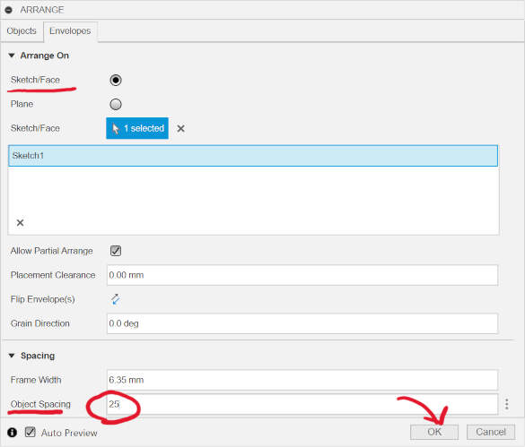
- Once you're happy with how everything is organized, click "OK."
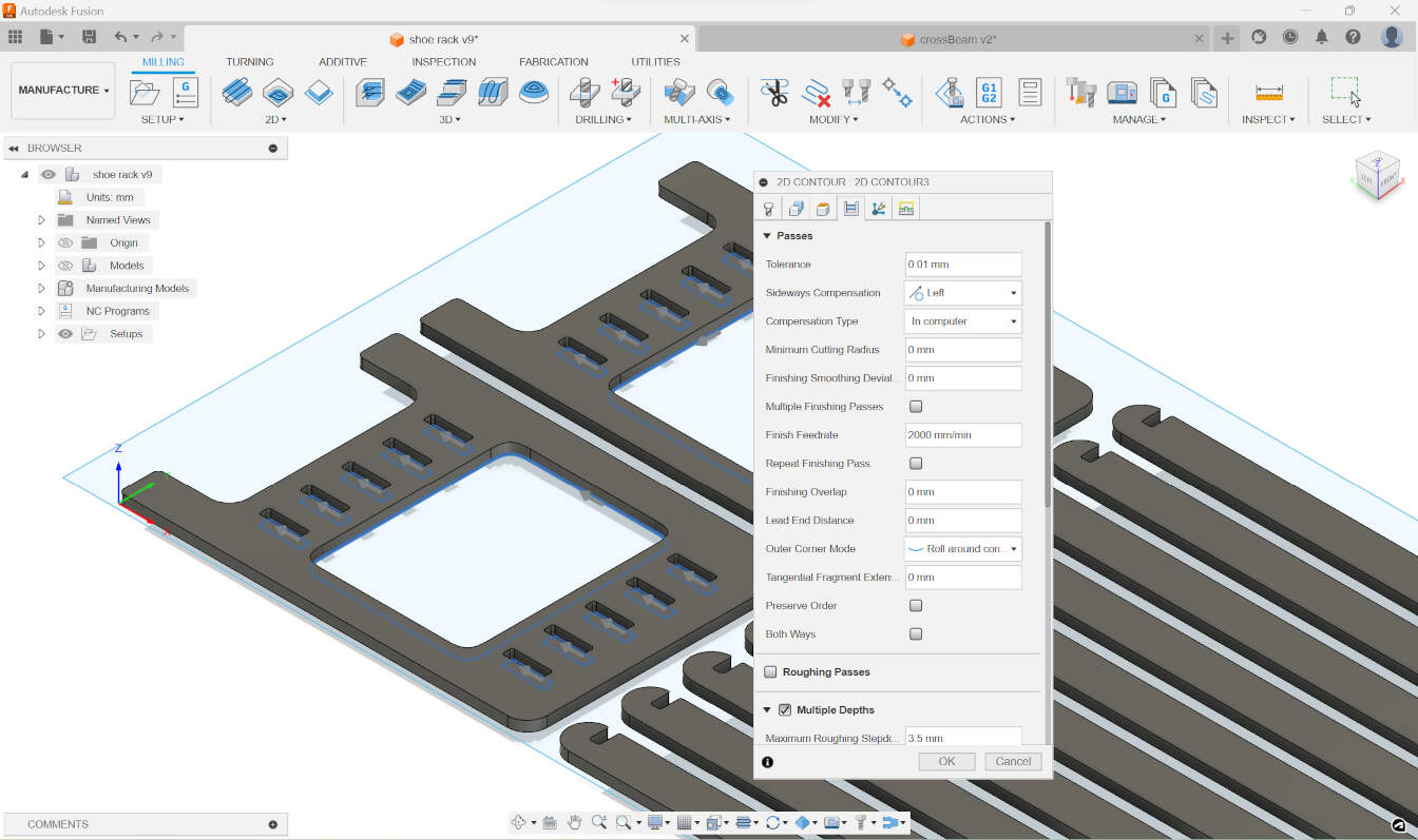
When setting up the machining process, I considered the use of two tool bits. Here’s how I planned it:
- 6mm Down-cut End Mill:
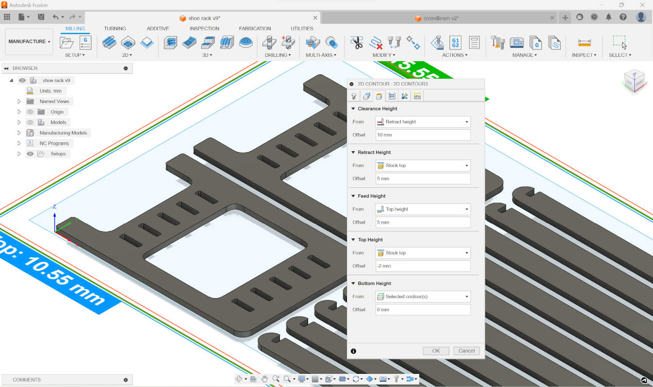
- For the first layer, I opted for a down-cut end mill.
- With this tool, I would only go 4mm deep.
- The purpose was to ensure that the top layer would remain clean and smooth.
- 6mm Upcut End Mill:
- For the remaining material, I chose an upcut end mill.
- This tool would be used to remove the bulk of the material.
- This would ensure that the bottom layer would also come out clean
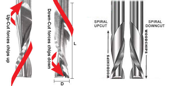
Regarding the actual tool bit being used, I mentioned that I would use two types of 6mm end mills. A down cut end mill works by pushing the chips downward, which is ideal for cutting materials like plywood,
where you want to avoid tear-out on the top surface. An upcut end mill, on the other hand, pulls the chips upward, where you want to avoid tear-out on the bottom surface. so by using both, I would get a clean cut on both sides :P
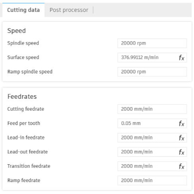
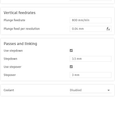
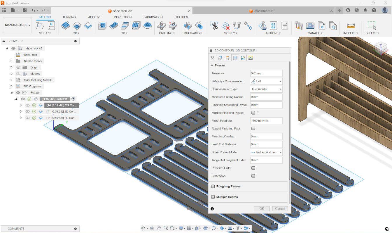
Regarding the feeds and speeds, the feed rate is the speed at which the cutter engages the material, and the speed is the rate at which the cutter rotates.
I used the following settings:
here are the settings for the 1st setup:
And here are the settings for the 2nd setup:
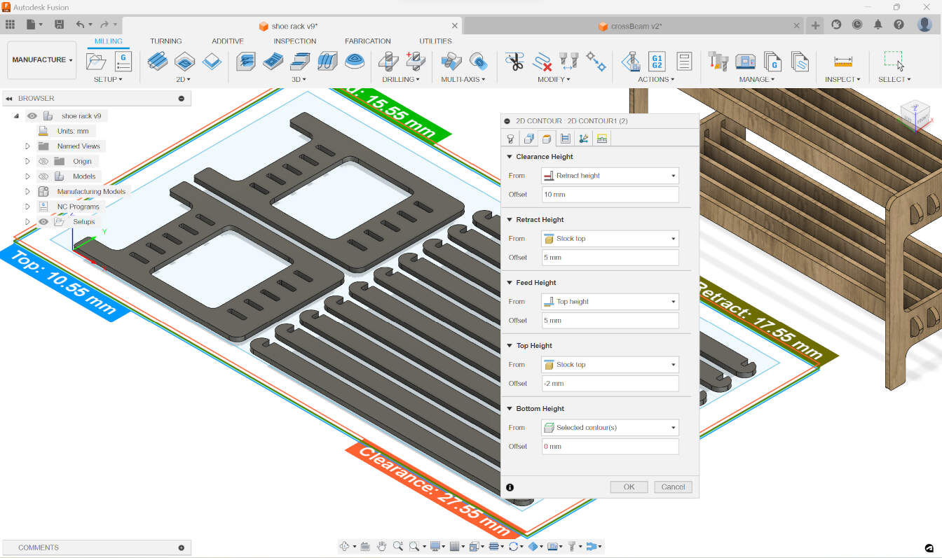
And here are the settings for the 3rd setup:
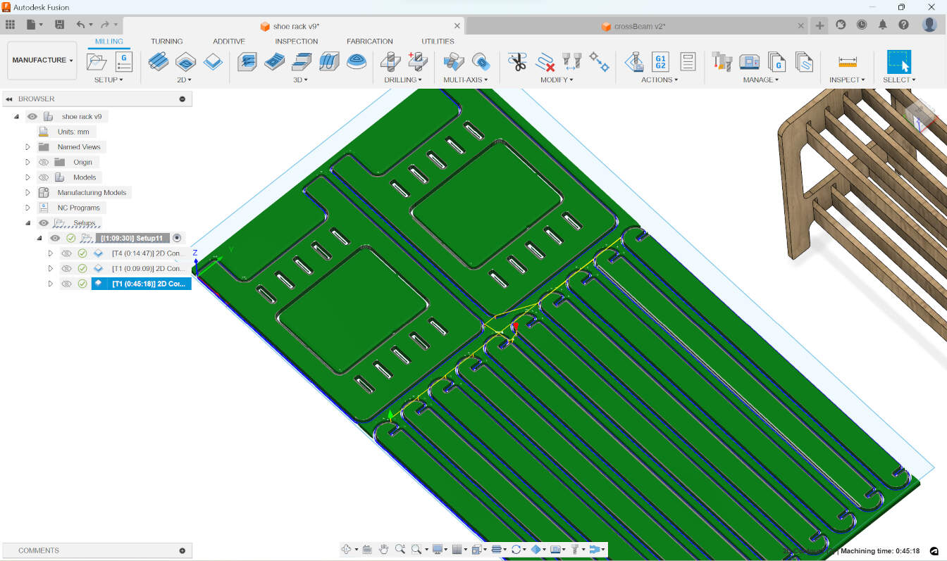
And here are the settings for the 4th setup:
After getting this settled, I posted the jobs to "post process" one by one and then saved the files to a USB stick.
Then I went to the lab and set up the machine.
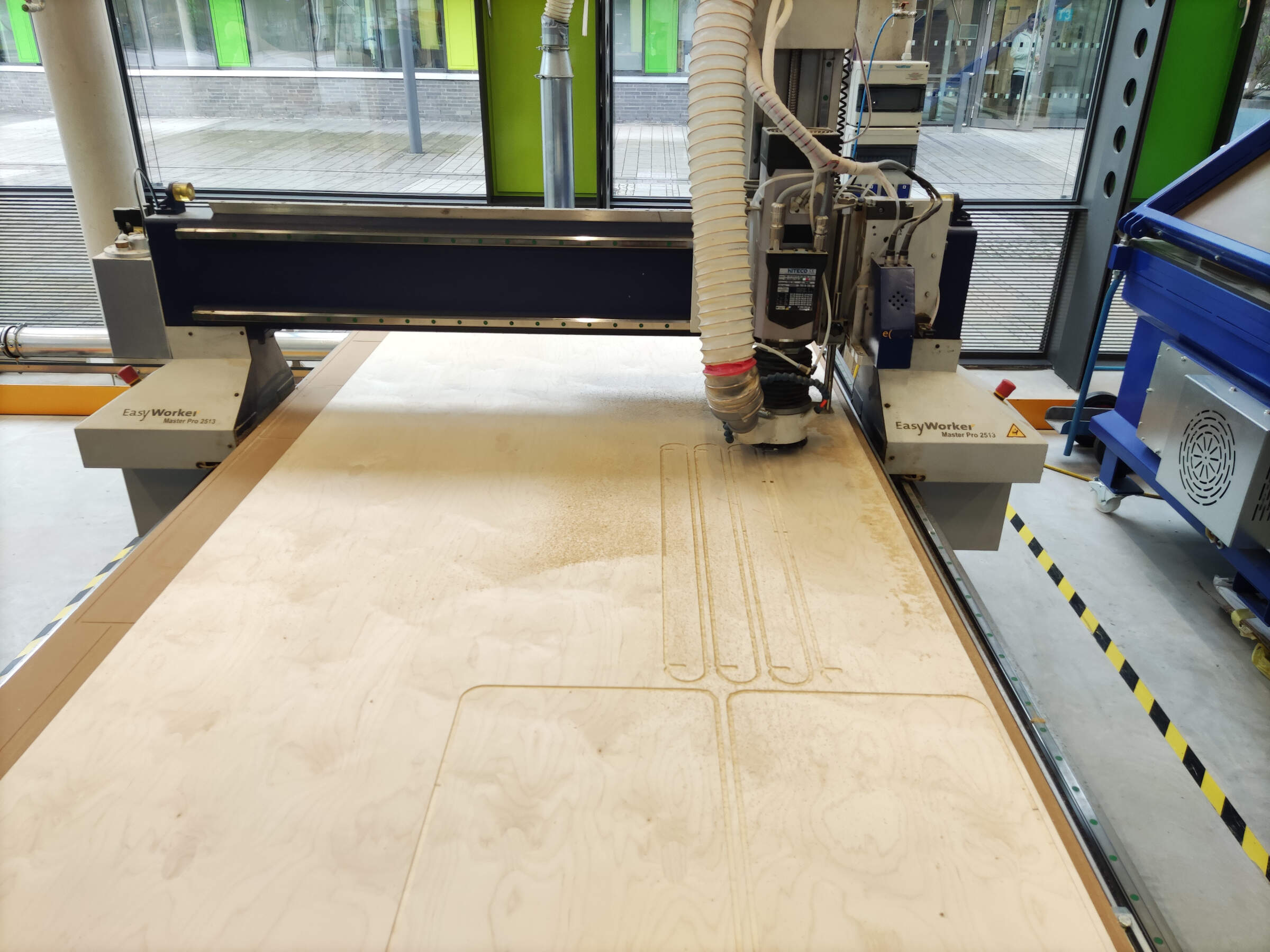
CNC milling
on the group assignment page I give a better description on how to operate the CNC we have at the lab, so here I will just include the checklist we go through before cutting
once i followed all of the steps on the checklist, and set up everything for the machine, I started the job.
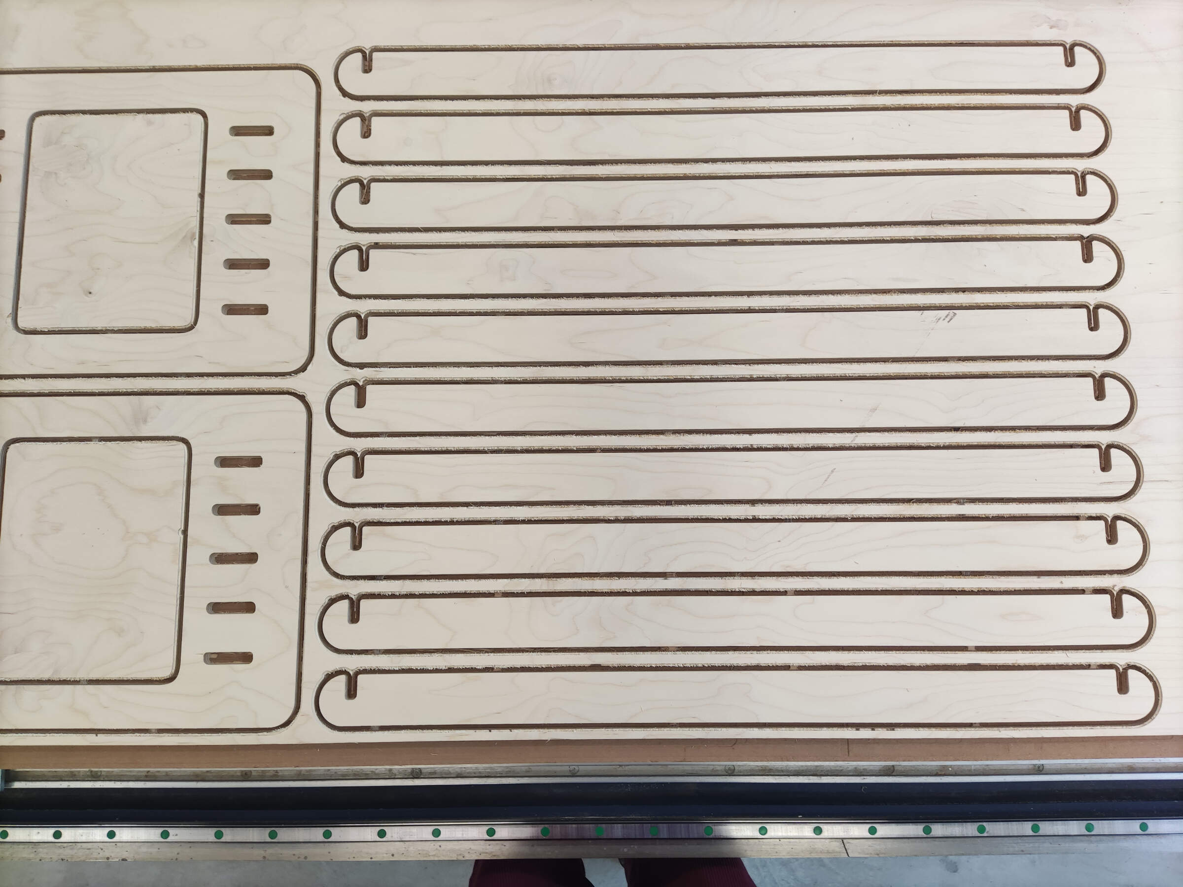
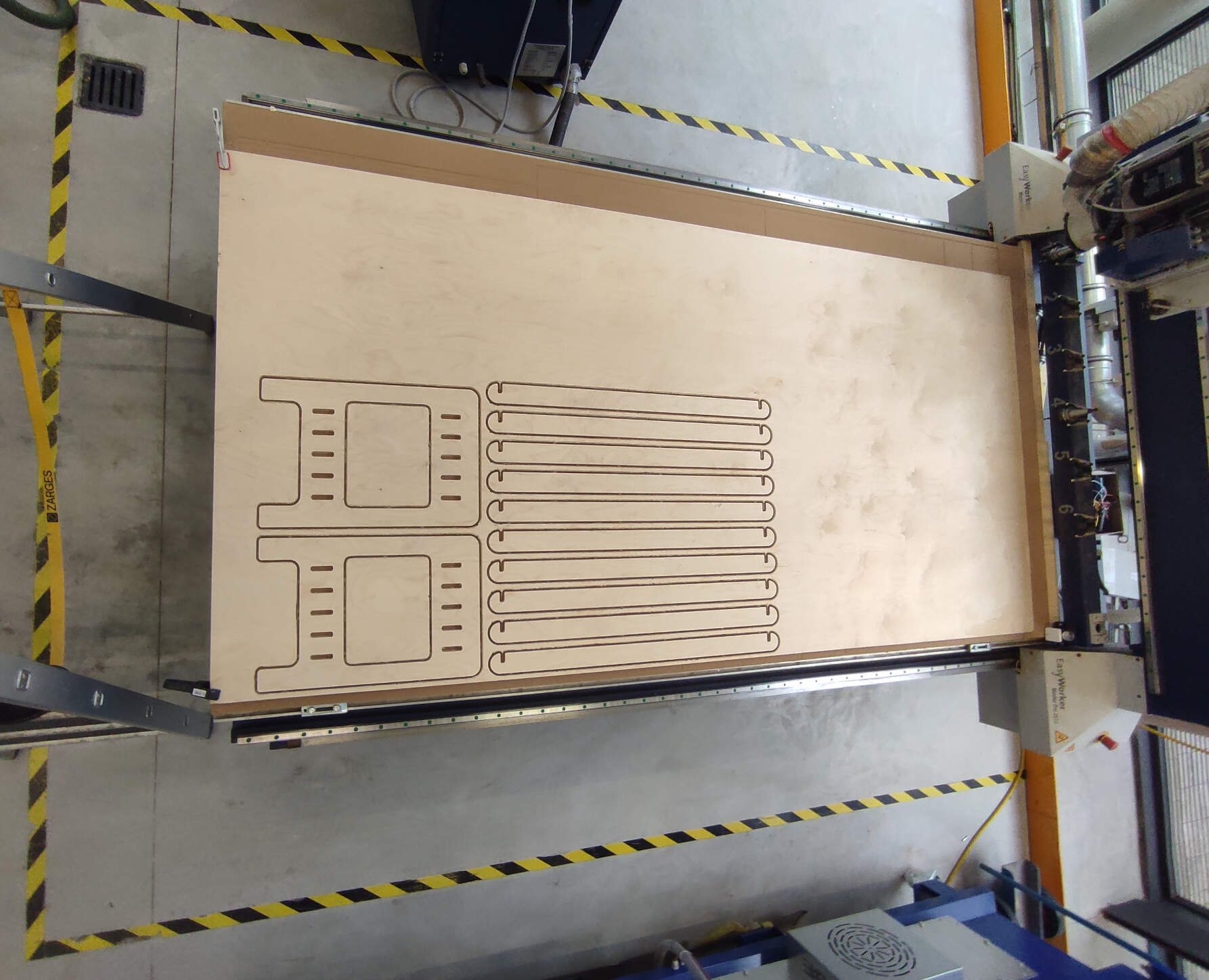
the first job was with the down cut mill that would only go 4mm deep, this went smoothly and the result was a top layer of the plywood with a clean outline of the parts.
the next job was to cut all of the slots and the inside parts,
this was done with a 6mm flat end upcut mill, the tool change process was done automatically by our machine so I to start this job,
I just had to load the file for it and send it to the machine.

The last cut was made with the same mill bit.
The only change was that this would cut all of the outside contours of the parts.
There was an issue with our dust collection system, where it wasn’t sucking up all the wood dust.
So, in between the cuts, I would use a separate vacuum to clean up a bit
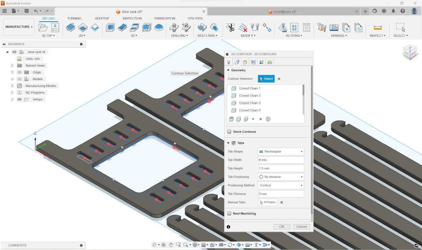
After the cutting was done, I removed them with a wood chisel and a hammer.
This was to break the tabs without damaging the first layer of the plywood.
Although I used two different types of mill bits to achieve a clean cut, I still had to sand the parts slightly to achieve a better fit.
Unfortunately, I forgot to add a tolerance for the press fit, so I had to sand more.
I used the … for the main sanding process, where I went over all of the sides of the pieces.
Then, I manually sanded the inside of the slots with sandpaper.
To make the parts fit, I sanded the ends of the crossbeams with a ..., for the final finish i used a fine grit sandpaper with the ... and just went over everything again.
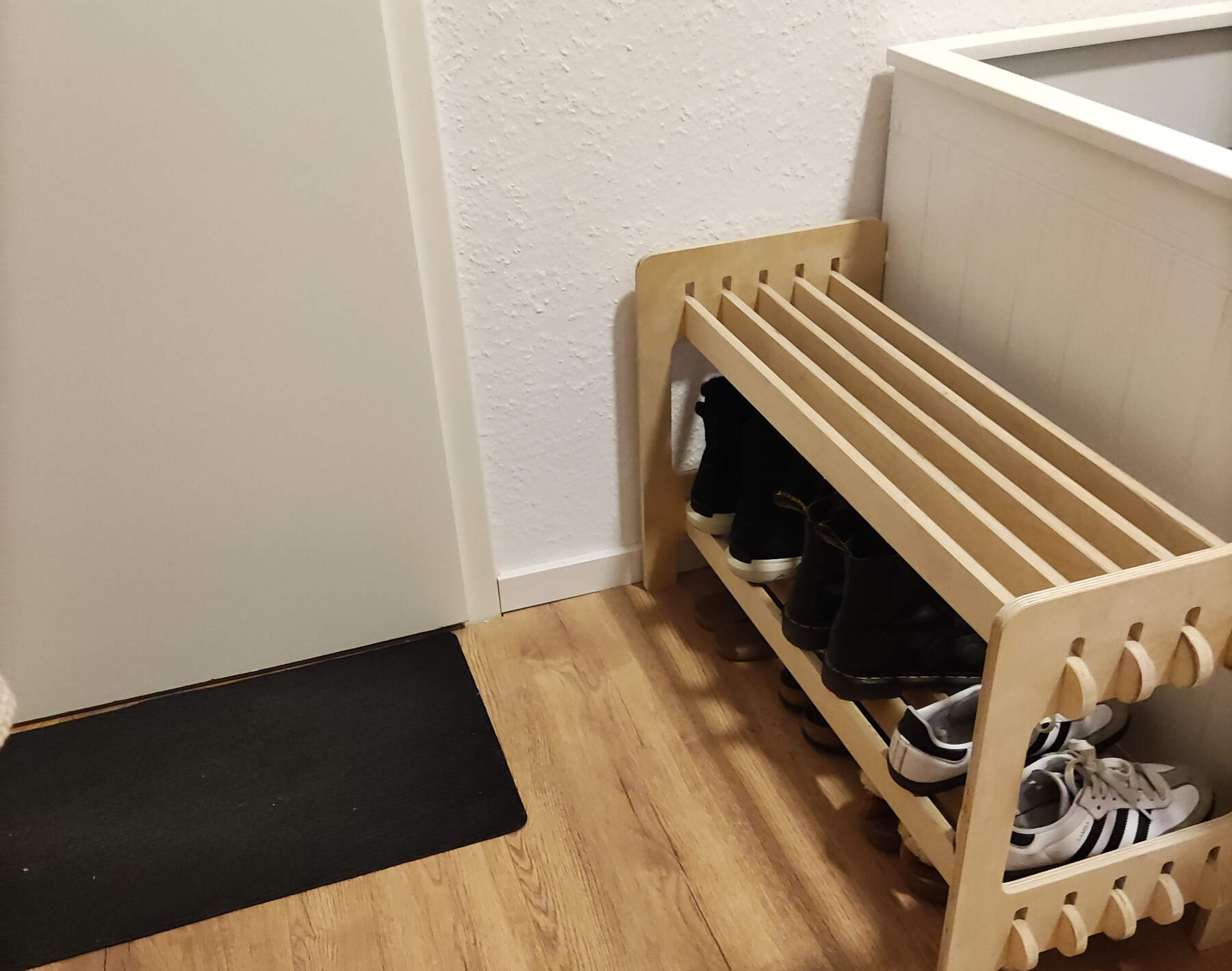
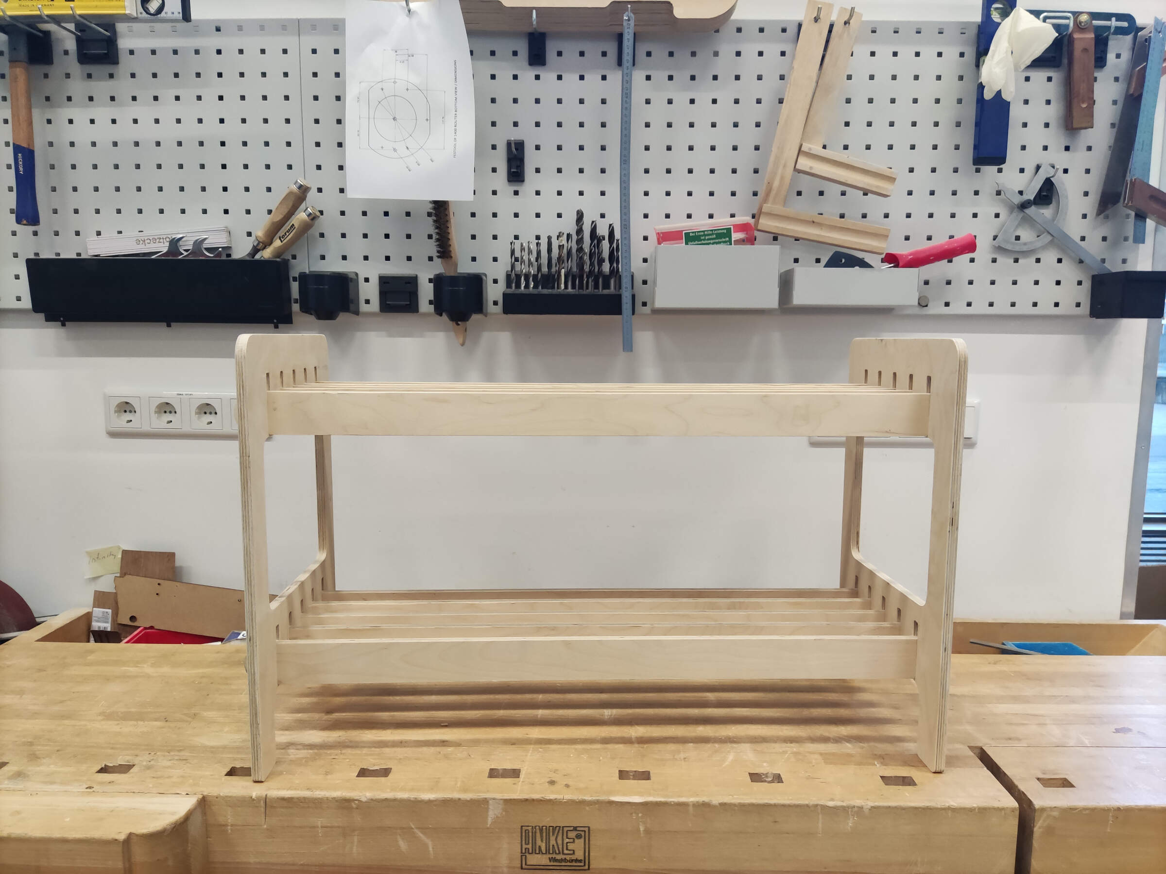
After the sanding, I assembled the shoe rack.
since everything was a tight fit I had to use a mallet to "convince" the parts into going to their proper places.

Although the end result of this weeks project wasnt what I originally planned to make, I’m still very happy with it! During this whole process of designing, milling, and assembling, I started to finally truly understand why my dad decided to make almost anything instead of buying it.
I remember watching him design and make various pieces of furniture in our home, even the smallest to the most complex things.
Now I understand why he did it—it’s a very rewarding process. And now I think I’m allergic to buying IKEA furniture.
It really holds up and is very sturdy. When I stood on top of it, it didn’t even move or shake. The joints held up very nicely and didn’t buckle at all, especially because of the lack of tolerance :)
It fits perfectly into it´s little space by my door, and it fits my weekly shoe rotation!