- compare as many tool options as possible
- write an application that interfaces a user with an input &/or output device that you made
FABACADEMY
FABACADEMY
For the group assignment, this week we have to compare as many tool options as possible. Below is a comparison of three different tools for creating applications that interface with microcontrollers: Flutter, MIT App Inventor, and Processing.
Description: Flutter is an open-source UI framework developed by Google. It allows you to build natively compiled applications for mobile, web, and desktop from a single codebase.
Description: MIT App Inventor is a visual development environment for creating Android apps. It’s beginner-friendly and uses a block-based programming approach.
Description: Processing is an open-source programming language and environment for creative coding and visual arts.
Here is a link to the group assignment page.
This week I decided to test out a few possibilities and options for the individual assignment. I wanted to understand how to use the bluetooth function on the nanoesp32 board, try out using MIT App Inventor and also test out the Processing software.
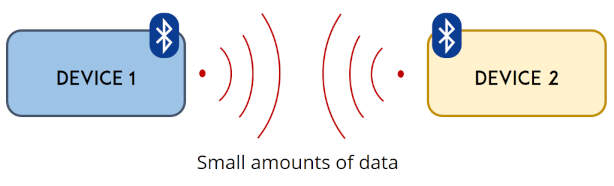
the arduino nano esp32 board, is really cool beccause as the name of this board suggests it is a combination of the arduino nano and the esp32. This board´s NORA- W106 moduel contains an esp32 chip, more specifically the esp 32 s3 and an onboard antenna. the esp 32 s3 has both wifi and bluetooth capabilities. but since for my project i plan on using blue tooht i ll focus on this feature. the esp32 supports Bluetooth 5 low energy (BLE). BLE is for short a power conserving variant of bluetooth. its primaraly used for short distance transmission of small amounts of data (low bandwidth). normal bluetooht is always on, but BLE is not. it is only on when a connection is initiated. this in turn means it consumes much less power than normal bluetooth
The esp 32 can act as a BLE server or a BLE client. and its easy to find BLe eamples for the esp32 in the esp 32 ble library in the arduino IDE environment. the code you write to use the bluethooth function should follow these steps:
the deconstruction of the code is as follows:
        #include <BLEDevice.h>
        #include <BLEUtils.h>
        #include <BLEServer.h>
        #define SERVICE_UUID "4fafc201-1fb5-459e-8fcc-c5c9c331914b"
        #define CHARACTERISTIC_UUID "beb5483e-36e1-4688-b7f5-ea07361b26a8"
Serial.begin(115200);
3.1. start the serial communication at 115200 baud rate.
        BLEDevice::init("BlueESP32");
        BLEServer *pServer = BLEDevice::createServer();
3.2. create the BLE device (I named it BlueESP32) and set it as the server
BLEService *pService = pServer->createService(SERVICE_UUID);
3.3. create a service for the BLE server with the UUID defined earlier
        BLECharacteristic *pCharacteristic = pService->createCharacteristic(
                                     CHARACTERISTIC_UUID,
                                     BLECharacteristic::PROPERTY_READ |
                                     BLECharacteristic::PROPERTY_WRITE
                                     );
3.4. create a characteristic for the service, with the UUID defined earlier, and set the properties to read and write.
pCharacteristic->setValue("Hello World");
3.5. This sets the characteristics value, in this case, the value is "Hello World"
        BLEAdvertising *pAdvertising = pServer->getAdvertising();
        pAdvertising->start();
3.6. Lastly start the service and start advertising
^^This code is the code you find when you open the BLE_server example in the arduino IDE. ( File > Examples > ESP32 BLE Arduino) here it is in its entirety:
            /*
                Based on Neil Kolban example for IDF: https://github.com/nkolban/esp32-snippets/blob/master/cpp_utils/tests/BLE%20Tests/SampleServer.cpp
                Ported to Arduino ESP32 by Evandro Copercini
                updates by chegewara
            */

            #include <BLEDevice.h>
            #include <BLEUtils.h>
            #include <BLEServer.h>

            // See the following for generating UUIDs:
            // https://www.uuidgenerator.net/

            #define SERVICE_UUID        "4fafc201-1fb5-459e-8fcc-c5c9c331914b"
            #define CHARACTERISTIC_UUID "beb5483e-36e1-4688-b7f5-ea07361b26a8"

            void setup() {
              Serial.begin(115200);
              Serial.println("Starting BLE work!");

              BLEDevice::init("Long name works now");
              BLEServer *pServer = BLEDevice::createServer();
              BLEService *pService = pServer->createService(SERVICE_UUID);
              BLECharacteristic *pCharacteristic = pService->createCharacteristic(
                                             CHARACTERISTIC_UUID,
                                             BLECharacteristic::PROPERTY_READ |
                                             BLECharacteristic::PROPERTY_WRITE
                                           );

              pCharacteristic->setValue("Hello World says Neil");
              pService->start();
              // BLEAdvertising *pAdvertising = pServer->getAdvertising();  // this still is working for backward compatibility
              BLEAdvertising *pAdvertising = BLEDevice::getAdvertising();
              pAdvertising->addServiceUUID(SERVICE_UUID);
              pAdvertising->setScanResponse(true);
              pAdvertising->setMinPreferred(0x06);  // functions that help with iPhone connections issue
              pAdvertising->setMinPreferred(0x12);
              BLEDevice::startAdvertising();
              Serial.println("Characteristic defined! Now you can read it in your phone!");
            }

            void loop() {
              // put your main code here, to run repeatedly:
              delay(2000);
            }
After understanding this, I followed another totorial, to turn on an off the onboard led of the nano esp 32 through bluetooth with my phone. in this totorial, by uploading this C++ code:
            // Turns an Arduino Nano ESP32 into a Bluetooth® Low Energy peripheral.
            // This BLE peripheral is providing a service that allows a BLE central
            // to switch on and off the internal LED of the Arduino Nano ESP32.
            // https://tutoduino.fr/
            // Copyleft 2023
            #include <ArduinoBLE.h>
            BLEService ledService("19b10000-e8f2-537e-4f6c-d104768a1214"); // Bluetooth® Low Energy LED Service
            // Bluetooth® Low Energy LED Switch Characteristic - custom 128-bit UUID, read and writable by central
            BLEByteCharacteristic switchCharacteristic("19b10000-e8f2-537e-4f6c-d104768a1214", BLERead | BLEWrite);
            const int ledPin = LED_BUILTIN; // internal LED pin
            void setup() {
              Serial.begin(9600);
              // set LED pin to output mode
              pinMode(ledPin, OUTPUT);
              // BLE initialization
              if (!BLE.begin()) {
                Serial.println("starting Bluetooth® Low Energy module failed!");
                while (1);
              }
              // set advertised local name and service UUID:
              BLE.setLocalName("LED");
              BLE.setAdvertisedService(ledService);
              // add the characteristic to the service
              ledService.addCharacteristic(switchCharacteristic);
              // add service
              BLE.addService(ledService);
              // set the initial value for the characeristic:
              switchCharacteristic.writeValue(0);
              // start advertising
              BLE.advertise();
              Serial.println("BLE LED Peripheral");
            }
            void loop() {
              // wait for a Bluetooth® Low Energy central
              BLEDevice central = BLE.central();
              // check if a central is connected to this peripheral
              if (central) {
                Serial.print("Connected to central: ");
                // print the central's MAC address:
                Serial.println(central.address());
                // while the central is still connected to peripheral:
                while (central.connected()) {
                  // if the remote device wrote to the characteristic,
                  // use the value to control the LED:
                  if (switchCharacteristic.written()) {
                    if (switchCharacteristic.value()) {   // any value other than 0
                      Serial.println("LED on");
                      digitalWrite(ledPin, HIGH);         // will turn the LED on
                    } else {                              // a 0 value
                      Serial.println(F("LED off"));
                      digitalWrite(ledPin, LOW);          // will turn the LED off
                    }
                  }
                }
                // the central has disconnected
                Serial.println("Disconnected from central: ");
              }
            }
After uploading this code to the nano esp32, I downloaded the LightBlue application on my phone, and connected to the "LED" device. Then, by writing 1 or 0 in the characteristic, I was able to turn on and off the onboard LED of the nano esp32. Pretty cool! Although for the final project, I will not be sending data through hex ;P
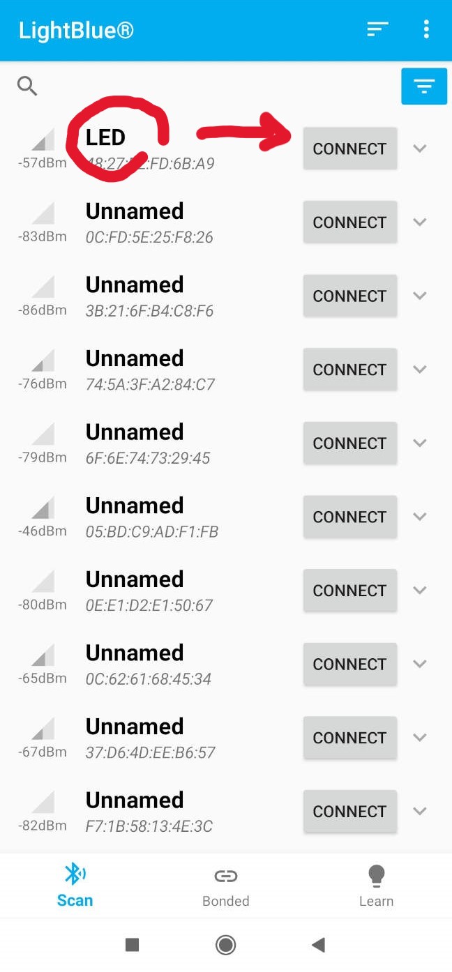
On the application, there is a list of available devices, remember that in the code we set the local name to "LED", so this is the name that should appear on the list. then click on the device to connect, when you connect to the device, a little pop up will appear "connected to device!"

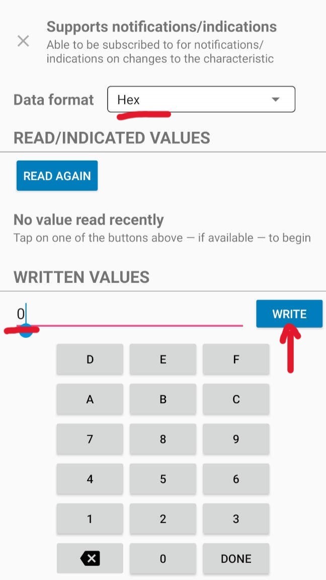
To write the hex numbers that controlls wheather or not the on board LED is on or off, choose the last option, here in bold you can see the advertised service UIDs, this is the service you created in the code. and then in smaller lettering this option displays "readable and writable".

When I send 1, the LED on the board turns on
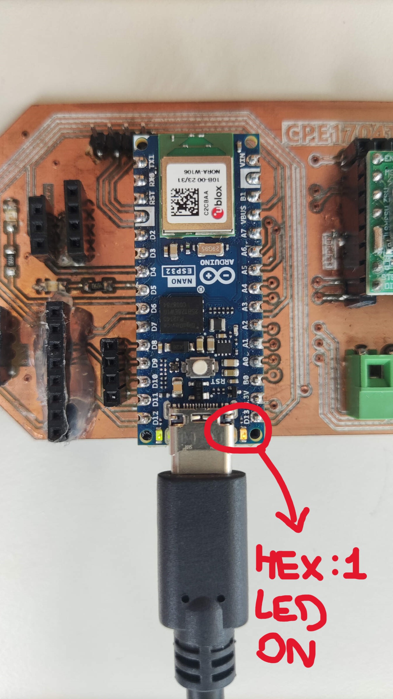
on board LED is on
When I send 0, the LED on the board turns off
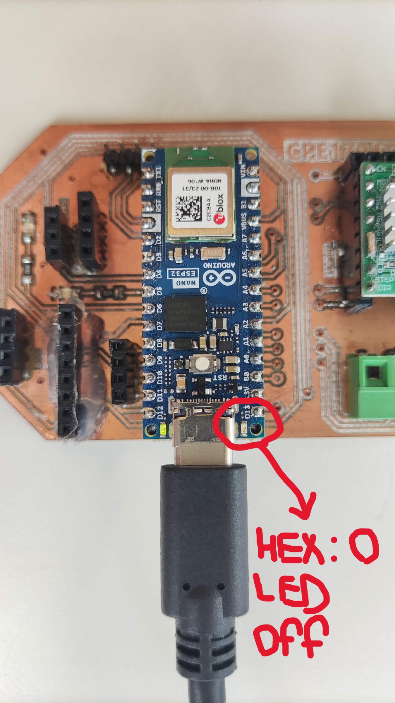
on board LED is off
What is happening here, is that the hex I send from the app, is recived by the board as a value, and then the board reads this value and turns the LED on or off accordingly. In other cases, if I wanted to make something more complex, for example a button, that when its clicked moves a servo, I would asign in the application code a value to the button, and then in the board code, I would read this value and move the servo accordingly.
processing is an open source software sketchbook that uses java as its programming language. and it works really well with arduino. in my case I will uplaod a program to my baord via arduino IDE and then use processing to create a GUI that will interact with the board (GUI = graphical user interface).
To start, I felt like a fish out of water, or to exagerate even more, I felt as if you asked a fish drowning in air, to write "an application that interfaces a user with an input &/or output device". obviously the fish would not know what to do at first. However we live in an age of information, and with a few searches on the internet I was able to find a few tutorials that helped me understand how to use processing with arduino (this made me feel like a fish that was given a glass of water to breathe in). if you are reading this, and also feel like a fish out of water, I recommend you check out these totorials: playlist for an intro to Processing and Control Arduino Using GUI (Arduino + Processing) and Connecting Arduino to Processing
Getting back on track, to start I followed the tutorial to control an LED. I used the board from electronics design week and uploaded the following code to the board:
            char val; // Data received from the serial port
            int ledPin = 3; // Set the pin to digital I/O 13
            boolean ledState = LOW; // To toggle our LED

            void setup()
            {
              pinMode(ledPin, OUTPUT); // Set pin as OUTPUT
              // Initialize serial communications at a 9600 baud rate
              Serial.begin(9600);
              establishContact(); // Send a byte to establish contact until receiver responds
            }

            void loop()
            {
              if (Serial.available() > 0) { // If data is available to read,
                val = Serial.read(); // Read it and store it in val

                if (val == '1') // If we get a 1
                {
                  ledState = !ledState; // Flip the ledState
                  digitalWrite(ledPin, ledState);
                }
                delay(100);
              }
              else {
                Serial.println("Hello, I am processing it!"); // Send back a message
                delay(50);
              }
            }

            void establishContact() {
              while (Serial.available() <= 0) {
                Serial.println("A"); // Send a capital A
                delay(300);
              }
            }
upload the arduino code first, make sure to set the right LED pin
            import processing.serial.*; //import the Serial library
            Serial myPort; //the Serial port object
            String val;
            // since we're doing serial handshaking,
            // we need to check if we've heard from the microcontroller
            boolean firstContact = false;

            void setup() {
              size(400, 400); //make our canvas 200 x 200 pixels big
              // initialize your serial port and set the baud rate to 9600
              String portName = "COM7"; //this setup is for windows port change the # to match your port
              myPort = new Serial(this, portName, 9600);
              myPort.bufferUntil('\n');
            }

            void draw() {
              //we can leave the draw method empty,
              //because all our programming happens in the serialEvent (see below)
            }

            void serialEvent( Serial myPort) {
              //put the incoming data into a String -
              //the '\n' is our end delimiter indicating the end of a complete packet
              val = myPort.readStringUntil('\n');
              //make sure our data isn't empty before continuing
              if (val != null) {
                //trim whitespace and formatting characters (like carriage return)
                val = trim(val);
                println(val);

                //look for our 'A' string to start the handshake
                //if it's there, clear the buffer, and send a request for data
                if (firstContact == false) {
                  if (val.equals("A")) {
                    myPort.clear();
                    firstContact = true;
                    myPort.write("A");
                    println("contact");
                  }
                }
                else { //if we've already established contact, keep getting and parsing data
                  println(val);

                  if (mousePressed == true)
                  { //if we clicked in the window
                    myPort.write('1'); //send a 1
                    println("1");
                  }

                  // when you've parsed the data you have, ask for more:
                  myPort.write("A");
                }
              }
            }
Run this code in processing, and by clicking with my mouse, I can turn the LED of my PCB on and off
Here I wanted to try out controlling a servo motor with processing. I used the same board from electronics design week, and plugged in my servo to the board. the arduino code for this is very simple:
#include ESP32Servo.h
As always, when using servos, aways include the servo library, in my case because I´m using a nano ESP32, I found out in week 11 the servo.h library does not work with is board, so instead I used the ESP32Servo.h library.
        Servo myServo;
        int servoPosition = 0; // Initial position
Servo myServo; declares an instance of the Servo class named myServo. int servoPosition = 0; initializes an integer variable servoPosition with an initial value of 0.
        void setup() {
          myServo.attach(2); // Connect servo to pin 9
          Serial.begin(9600);
        }
In the void setup() function, myServo.attach(2); associates the servo motor with pin 2 on the Arduino board. Serial.begin(9600); initializes serial communication at a baud rate of 9600.
        void loop() {
          if (Serial.available() > 0) {
            int angle = Serial.parseInt(); // Read angle from Processing
            if (angle >= 0 && angle <= 180) {
              myServo.write(angle);
              delay(500); // Delay for servo movement
            }
          }
        }
            #include <Servo.h>

            Servo myServo;
            int servoPosition = 0; // Initial position

            void setup() {
              myServo.attach(2); // Connect servo to pin 9
              Serial.begin(9600);
            }

            void loop() {
              if (Serial.available() > 0) {
                int angle = Serial.parseInt(); // Read angle from Processing
                if (angle >= 0 && angle <= 180) {
                  myServo.write(angle);
                  delay(500); // Delay for servo movement
                }
              }
            }
upload this code to the board, and then run the following code in processing
            import processing.serial.*;

            Serial arduinoPort; // Serial port for communication with Arduino
            boolean servoMoved = false; // Flag to track servo position
            Button servoButton; // Declare the button

            void setup() {
              size(400, 200);
              String[] portNames = Serial.list();
              if (portNames.length > 0) {
                arduinoPort = new Serial(this, portNames[0], 9600); // Change baud rate if needed
              } else {
                println("No Arduino port found. Make sure it's connected.");
                noLoop();
              }

              // Create the button
              servoButton = new Button(width / 2 - 50, height / 2 - 20, 100, 40, "Move Servo");
              servoButton.onClick(() -> {
                if (!servoMoved) {
                  arduinoPort.write("90"); // Send "90" to Arduino
                  servoMoved = true;
                } else {
                  arduinoPort.write("0"); // Send "0" to return servo to initial position
                  servoMoved = false;
                }
              });
            }

            void draw() {
              background(220);
              // Display the button
              servoButton.display();
            }

            class Button {
              float x, y, w, h;
              String label;
              Runnable onClickAction;

              Button(float x, float y, float w, float h, String label) {
                this.x = x;
                this.y = y;
                this.w = w;
                this.h = h;
                this.label = label;
              }

              void display() {
                // Button appearance
                fill(255);
                stroke(0);
                rect(x, y, w, h, 10); // Rounded corners
                fill(0);
                textAlign(CENTER, CENTER);
                textSize(16);
                text(label, x + w / 2, y + h / 2);
              }

              void onClick(Runnable action) {
                onClickAction = action;
              }

              void checkClick(float mx, float my) {
                if (mx > x && mx < x + w && my > y && my < y + h) {
                  onClickAction.run();
                }
              }
            }

            void mousePressed() {
              servoButton.checkClick(mouseX, mouseY);
            }
In summary, this code sets up a simple graphical interface with a button that interacts with an Arduino via a serial port. When the button is clicked in the Processing window, the Arduino receives a command to move the servo motor 90 degrees. Clicking the button again sends a command to return the servo to its initial position.