browse through the data sheet for your microcontroller
compare the performance and development workflows for other architectures
Individual assignments
write a program for a microcontroller development board that you made,
to interact (with local input &/or output devices) and communicate (with remote wired or wireless devices)
extra credit: use different languages &/or development environments
extra credit: connect external components to the board
I want to learn at least two programming languages. I've started to dip my feet into programming with Arduino IDE, which uses a language that is a mix of C and C++. I've also started to learn Python. I found a free online course on coddy.tech called "Introduction to Python," and I plan to do a few lessons a day until I complete the course and become a Python wiz 😎. Jokes aside, I chose to learn Python because of my general curiosity and desire for more knowledge. It may also be useful for future assignments or my final project. Plus, then I can show off to my dad that I know a programming language he doesn't.
Embedded programming involves writing code for devices that aren’t traditional computers.
These devices can be anything from appliances, tools, or instruments like routers, smart TVs, or Mars rovers.
Unlike general software development, where applications run on standard operating systems, embedded systems are designed specifically for particular tasks.
Group assignment
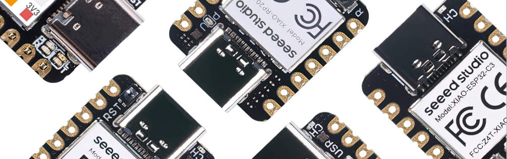
The microcontroller we used here at the lab to make our PCBs is the Seeeduino XIAO.
The Seeeduino XIAO is the smallest Arduino compatible board in Seeed Studio's product line.
It is an Arduino microcontroller that is based on the Atmel SAMD21 microcontroller.
The SAMD21 is a series of microcontrollers developed by Atmel, a subsidiary of Microchip Technology, which is based on a 32-bit ARM Cortex-M0+ processor.
The SAMD21 is designed for use in industrial and consumer applications that require a high level of performance and low power consumption.
The SAMD21 is also designed to be compatible with the Arduino IDE, which makes it easy to use for beginners and professionals alike.
After completing this assignment, I went through the data sheet again, to see if the problem I had with the board was mentioned in the data sheet, and it was on the 11th page section 2.1.6 Bootloader, the solution was to reset the board.
I will talk more about this in the individual assignment section,but you can refer to the this data sheet to find this solution.
Microcontroller:
It features the ATSAMD21G18A-MU, an ARM Cortex-M0+ 32-bit 48MHz CPU with 256KB Flash and 32KB SRAM.
Pin Configuration:
Digital Interfaces: 11 digital pins.
Analog Interfaces: 11 analog pins.
PWM Interfaces: 10 PWM pins (d1-d10).
Other Interfaces: 1 DAC output pin (D0), 1 SWD pad interface, 1 I2C interface, 1 SPI interface, and 1 UART interface.
Indicators: LEDs for power, transmit (TX), receive (RX), and blinking (L).
Size:
20.5mm x 17.5mm
Power and Connectivity:
Type-C Interface: For power supply and code download.
Voltage Compatibility: Operates at 3.3V.
DC-DC Converter: Converts 5V to 3.3V for powering the device.
Embedded programming involves writing code for devices that aren’t traditional computers.
These devices can be anything from appliances, tools, or instruments like routers, smart TVs, or Mars rovers.
Unlike general software development, where applications run on standard operating systems, embedded systems are designed specifically for particular tasks.
So far my experience with this has been very limited. When I was around 14, I messed around with an Arduino Uno and an ESP32, a breadboard, and other components like servos, LEDs, and sensors.
However, that was a while ago and I don't remember much, so I had to go back and relearn the basics.
For this assignment, I wanted to create a program that would read the input from a utrasonic sensor and use that input to control the brightness of an LED depending on the distance of the object from the sensor. I did this with Arduino IDE
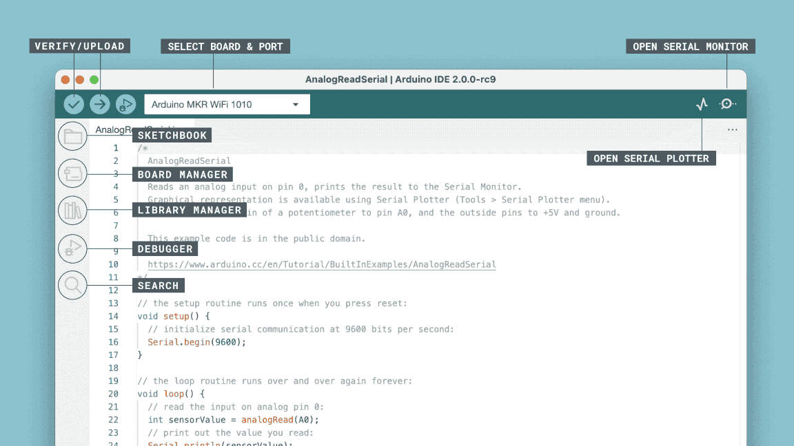
Arduino IDE
Arduino is an open-source electronics platform that allows you to create interactive electronic projects. It consists of both hardware (the Arduino board, but in the case of fab academy I will be using the pcb I made on week 4) and software (the Arduino IDE).
Arduino IDE is a cross-platform application that is written in functions from C and C++.
In the Arduino IDE, a program is called a “sketch.”
Click on File > New to create a new sketch.
You’ll see two default functions in your sketch:
setup(): This function runs once when the Arduino starts up.
loop(): This function runs repeatedly after setup() completes.
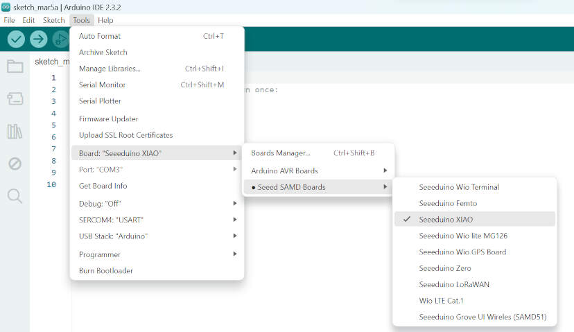
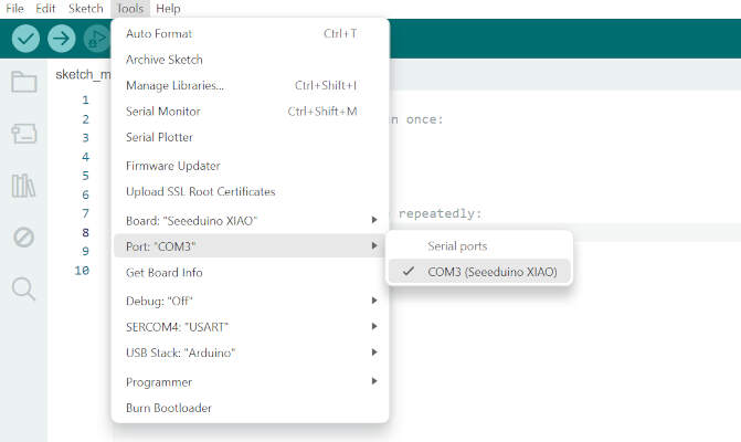
To start, You need to tell the intergrated developement eviroment which board you are using and which port its connected to, in my case "tools">"board">"seeeduino xiao".
Then tell yoiu enviroment which serial port to use, "tools">"port">"COM3" . one way to check if the board is connected is to check if your computer recognizes it, you can do this by going to "device manager" and checking if the board is listed under "ports (COM & LPT)"
After this, I wrote a simple code to test the board. I used the blink example that comes with the Arduino IDE.
This code makes the LED connected to pin 8 blink on and off every second.
To upload the code to the board, I clicked on the right arrow button on the top left corner of the IDE.
After a few seconds, the LED started blinking.
For this assignment, I wanted to create a program that would read the input from a utrasonic sensor and use that input to control the brightness of an LED depending on the distance of the object from the sensor.
Ultrasonic Sensor
On an ultrasonic sensor, there is an eco pin and a trig pin. The eco pin is the input and the trig pin is the output.
When the trig pin is set to high, the sensor sends out a sound wave and waits for it to bounce back.
When the sound wave bounces back, the eco pin goes high and the time it took for the sound wave to bounce back is measured.
We can use this time to calculate the distance of the object from the sensor. to do this we can use the following formula:
distance = (time * rate) / 2
target distance = (ping time * speed of sound) / 2
Where time is the time it took for the sound wave to bounce back (so ping time) and rate is the speed of sound in air (34300 cm/s) and we divide by 2 because the sound wave has to travel to the object and back to the sensor, but the distance we want to measure is only the distance to the object which is half the distance the sound wave traveled.
In the first part in the program, I set up the pins connected to the microcontroller and the ultrasonic sensor. I also defined the variables I would be using in the program with floats because the distance would be a decimal number.
		int trigPin = 3; // Sensor trigger/control pin connected to Seeeduino Xiao pin 3
		int echoPin = 5; // Sensor echo pin connected to Seeeduino Xiao pin 5
		int ledPin = 8; // LED pin connected to Seeeduino Xiao pin 8

		float pingTime; // Time for ping to travel to target and return
		float targetDistance; // Distance from sensor to target
		float speedOfSound = 343; // Speed of sound in meters per second (at 20°C)
In the void setup:
Turn on the serial port with: Serial.begin(9600);
Set the trig pin as an output with: pinMode(trigPin, OUTPUT);
Set the echo pin as an input with: pinMode(echoPin, INPUT);
In the void loop:
Here i need to make a measurement of the ping time. To do this, I set the trig pin to low then pause it, then set it high and pause it again, then set it low again. This creates the trigger that tells the sensor to send the ping.
Set the trig pin to low with: digitalWrite(trigPin, LOW);
Wait for 2000 microseconds with: delayMicroseconds(2000);
Set the trig pin to high with: digitalWrite(trigPin, HIGH);
Wait for 15 microseconds with: delayMicroseconds(15);
Set the trig pin to low with: digitalWrite(trigPin, LOW);
Now that the ping has been sent, I need to measure it.
pulseIn()is a function that measures the time it takes for a pin to go from low to high and back to low.
echoPin the pin that it reads from
HIGH tells the microcontroller that the sensor willbe sending a high signal
10000, there are a million microseconds in a second
note: Do the division with a floating point number, to force it to do floating point math, which avoids it from giving me strange integer operations.
       pingTime = pulseIn(echoPin, HIGH); // Measure pingTime at echoPin in microseconds
       pingTime = pingTime / 1000000.; // Convert ping time to seconds
       (the dot at the end of the number is to force it to do floating point math)
Now that I have the ping time, I can calculate the distance of the object from the sensor.
I do this by using the formula I mentioned earlier plus a few more steps to convert the distance from meters to centimeters and print the result to the serial monitor.
		targetDistance = speedOfSound * pingTime; // Calculate distance in meters
		targetDistance = targetDistance / 2; // Account for round trip of ping to target
		targetDistance *= 100; // Convert to centimeters

		Serial.print("Target Distance: ");
		Serial.print(targetDistance);
		Serial.println(" cm");
Now that I have the distance, I can use it to control the brightness of the LED.
First, I set up a variable called brightness to store the value of the brightness of the LED.
Then I use an if statement to check if the target distance is less than or equal to 2. If it is, the LED will turn off.
If the target distance is greater than 2, I use the map function to map the target distance to a value between 0 and 255. This will allow the LED to gradually increase in brightness as the target distance increases.
Finally, I use the analogWrite function to set the brightness of the LED using PWM.
Then I use the delay function to pause the program for 1500 milliseconds.
		int brightness;
		if (targetDistance <= 2) {
		  brightness = 0; // LED off
		} else {
		  brightness = map(targetDistance, 2, 10, 0, 255); // Gradual brightness increase
		}
		analogWrite(ledPin, brightness); // Set LED brightness using PWM

		delay(1500);
Here is the final code :)
int trigPin = 3; // Sensor trigger/control pin connected to Seeeduino Xiao pin 3
int echoPin = 5; // Sensor echo pin connected to Seeeduino Xiao pin 5
int ledPin = 8; // LED pin connected to Seeeduino Xiao pin 8
float pingTime; // Time for ping to travel to target and return
float targetDistance; // Distance from sensor to target
float speedOfSound = 343; // Speed of sound in meters per second (at 20°C)
void setup() {
Serial.begin(9600); // Turn on serial port
pinMode(trigPin, OUTPUT); // Sensor trig pin is an output
pinMode(echoPin, INPUT); // Sensor echo pin is an input
pinMode(ledPin, OUTPUT); // LED pin is an output
}
void loop() {
digitalWrite(trigPin, LOW); // Set the trig pin low
delayMicroseconds(2000); // Pause to let signal settle
digitalWrite(trigPin, HIGH); // Set trig pin to high
delayMicroseconds(15); // Pause in high state
digitalWrite(trigPin, LOW); // Bring trig pin back to low
pingTime = pulseIn(echoPin, HIGH); // Measure pingTime at echoPin in microseconds
pingTime = pingTime / 1000000.; // Convert ping time to seconds
targetDistance = speedOfSound * pingTime; // Calculate distance in meters
targetDistance = targetDistance / 2; // Account for round trip of ping to target
targetDistance *= 100; // Convert to centimeters
Serial.print("Target Distance: ");Serial.print(targetDistance);Serial.println(" cm");
// Adjust LED brightness based on target distance
int brightness;if (targetDistance <= 2) {brightness = 0; // LED off
} else {brightness = map(targetDistance, 2, 10, 0, 255); // Gradual brightness increase
}analogWrite(ledPin, brightness); // Set LED brightness using PWM
delay(1500);
}
After I uploaded the code to the board via a USB cable, I connected the ultrasonic sensor to the board.
The red wire connects the 5V pins together, the black wire is connects the ground pins together, the orange wire connects pin 3 to the trig pin on the sensor, and the purple wire connects pin 5 to the echo pin on the sensor.
After the case was printed, I connected the sensor to the board and the board to my computer and uploaded the program...
But now my computer was not recognizing the microcontroller😢! My instructor Ahmed, said that this might be a problem with the Xiao boards and that to fix it we should reset it, it was a process of trial and error since we weren´t 100% sure of the solution, but in the end it did work. After solving the issue I searched on google to see if others have had the same problem as well, and yes. This is a seeed studio forum where others have sought out help with this issue and the solution offered was the same one my instructor had suggested, here is the link to the forum.
Solve this problem by the following operation:
Connect the Seeeduino XIAO to your computer.
Use tweezers or short lines, or in my case short a line connected to a screw driver, to short the RST pin, you can find this pin by looking at the left side of the microcontroller where it says "RST" the pin should be an exposed golden circle.
The orange LED lights flicker on and light up.
At this point, the chip enters Bootloader mode and the burn port appears again.
Finally, I uploaded the program again… And voilà! It works! The further the object moves from the sensor, the brighter the yellow LED gets. Conversely, as it gets closer, the LED dims. When the object is approximately 2cm away from the sensor, the LED is completely off.
Extra credit: use different languages &/or development environments
I´m still trying to learn python, so I´m not ready yet to use it for this assignment, but to start to familiarize my self with the language I followed and wrote a program that draws a tree with the turtle graphics.
import turtle# Create a turtle objectmy_turtle = turtle.Turtle()# Set the initial positionmy_turtle.left(90)my_turtle.up()my_turtle.backward(200)my_turtle.down()# Define a function to draw branchesdef draw_branch(branch_length):if branch_length < 10:returnelse:my_turtle.forward(branch_length)my_turtle.left(30)draw_branch(branch_length * 0.7)my_turtle.right(60)draw_branch(branch_length * 0.7)my_turtle.left(30)my_turtle.backward(branch_length)# Draw the treedraw_branch(100)# Close the turtle graphics windowturtle.done()
Programming with different boards
Throughout the Fab Academy, I used many different boards, and I ran into different problems with each one.
I used an Arduino Nano ESP32 during input devices week,
and a ATtiny1614 and an ESP32 S3 for my final project.
For each board there was a diferent way to program it, for example the ESP32 S3 I used the platformio extension in visual studio code, wheras for the ATtiny1614 I used the Arduino IDE, in this link here I explain the how I program these baords and how I made them, and here you can see the code I used for both boards