Individual Assignment:
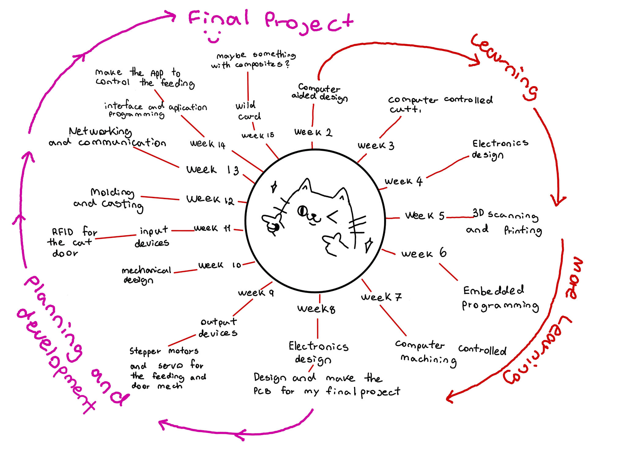
This week, I revisited the spiral development planning I made during week one and updated it, looking back at it more realistically. The first weeks were just for learning, and there wasn't much I did for the actual final project except for the 3D design and some planning. This week, I planned to control the servo motor and the stepper motors that will be essential for the workings of my final project.
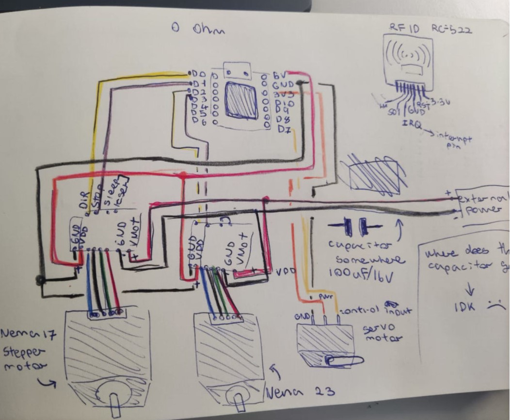
During the last week, I established what key electronic components I needed and that I had to house in the final PCB for my project. For the feeding mechanism, I will use two stepper motors: one stronger one (to move/spin the deposit and screw mechanism), the NEMA 23 stepper motor, and a less powerful one to spin the Archimedes screw and feed the cats, which will be the NEMA 17 stepper motor. Then, for the cat doors, I will use a servo to lock the door and the RFID to identify the cat.
Controlling stepper motors:
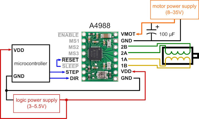
For the guts of the project, I will use the A4988 stepper motor driver, and a NEMA 17 stepper motor to spin and control the Archimedes screw that will feed the cats. I will be using this week to further develop my project and test the motor and the code to control it.
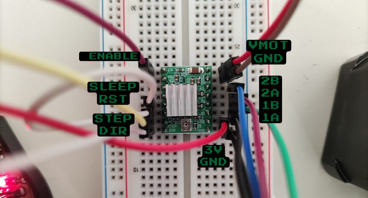
To create the circuit, I will be following this simple circuit diagram and using the PCB I made during production week. The new PCB I've designed is not completely finished, as the necessary components have not been soldered yet. The diagram depicts the Pololu driver, with its step and direction pins connected to the microcontroller. The sleep and reset pins are also connected to each other. Additionally, the motor's 4-pin connector is linked to the driver.
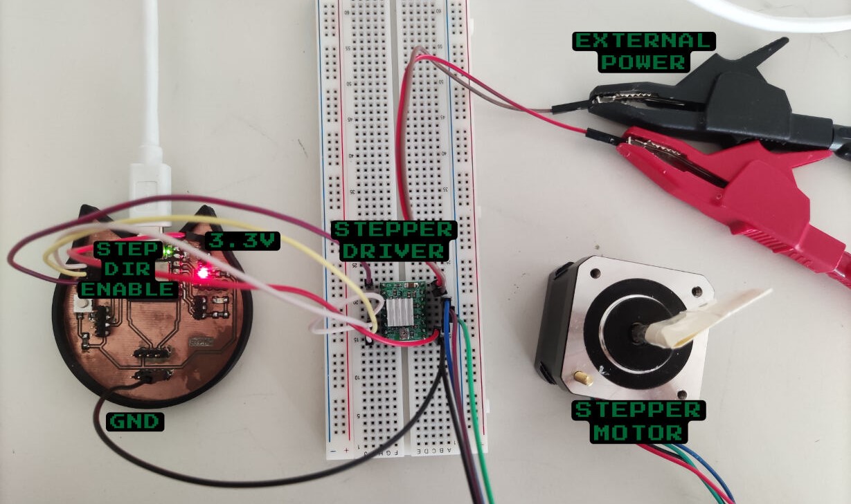
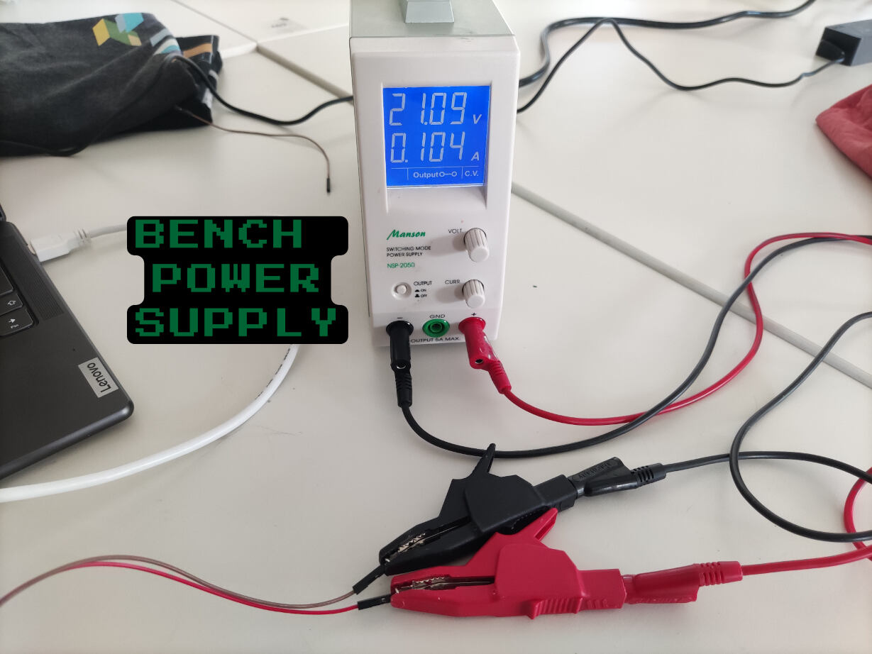 To create this circuit I used the PCB I made during the electronics production week, a bread board for the stepper driver connections, and a DC bench power supply to power the motor.
An external power supply ranging from 8V to 35V is connected to the VMOT and ground pins on the driver.
To power the driver itself, it is connected to a logic power supply of approximately 3V to 5V. In my case, this logic power supply will be provided by the microcontroller connected to my computer.
I also followed along with the sketches I made during the previous week.
To create this circuit I used the PCB I made during the electronics production week, a bread board for the stepper driver connections, and a DC bench power supply to power the motor.
An external power supply ranging from 8V to 35V is connected to the VMOT and ground pins on the driver.
To power the driver itself, it is connected to a logic power supply of approximately 3V to 5V. In my case, this logic power supply will be provided by the microcontroller connected to my computer.
I also followed along with the sketches I made during the previous week.
Creating the circuit:
To create this circuit I used the PCB I made during the electronics production week, a bread board for the stepper driver connections, and a DC bench power supply to power the motor.
| Wire Color | Connection to Stepper Driver | Other connections |
|---|---|---|
| Blue | 2B | stepper motor |
| Pink | 2A | stepper motor |
| Green | 1A | stepper motor |
| Black | 1B | stepper motor |
| Red | 3V | 3V on PCB |
| Black | GND | GND on PCB |
| Yellow | STEP | Pin 1 on PCB |
| White | DIR | Pin 2 on PCB |
| Pinkish Purple | ENABLE | Pin 3 on PCB |
| 2nd White | SLEEP/RST | -------- |
Controlling stepper motors:
I did some digging in the world wide web and I found this code by last minute engineers and I used it as a base to start with
	// Define pin connections & motor's steps per revolution
	const int dirPin = 2;
	const int stepPin = 3;
	const int stepsPerRevolution = 200;

	void setup()
	{
		// Declare pins as Outputs
		pinMode(stepPin, OUTPUT);
		pinMode(dirPin, OUTPUT);
	}
	void loop()
	{
		// Set motor direction clockwise
		digitalWrite(dirPin, HIGH);

		// Spin motor slowly
		for(int x = 0; x < stepsPerRevolution; x++)
		{
			digitalWrite(stepPin, HIGH);
			delayMicroseconds(2000);
			digitalWrite(stepPin, LOW);
			delayMicroseconds(2000);
		}
		delay(1000); // Wait a second

		// Set motor direction counterclockwise
		digitalWrite(dirPin, LOW);

		// Spin motor quickly
		for(int x = 0; x < stepsPerRevolution; x++)
		{
			digitalWrite(stepPin, HIGH);
			delayMicroseconds(1000);
			digitalWrite(stepPin, LOW);
			delayMicroseconds(1000);
		}
		delay(1000); // Wait a second
	}
On the Arduino IDE, I changed the pins and other parts of this code to match my setup. This was a good start, but what I really wanted was to simulate a miniaturized version of the guts of my project, at least the screw part.
	// Define pin numbers
	const int dirPin = 1; // direction
	const int stepPin = 2; // step
	const int enaPin = 3; // enable

	// Variables for controlling the feeding mechanism
	const int stepsPerTurn = 200; // Number of steps per full turn (adjust as needed)
	int totalTurns = 0; // Counter for total turns

	void setup() {
	  // Define all pins as outputs
	  pinMode(stepPin, OUTPUT);
	  pinMode(dirPin, OUTPUT);
	  pinMode(enaPin, OUTPUT);

	  // Enable the motor driver
	  digitalWrite(enaPin, LOW);
	}


	void loop() {
	  // Set the rotation direction to one particular direction (e.g., clockwise)
	  digitalWrite(dirPin, HIGH);

	  // Prompt the user to input the desired number of turns
	  Serial.println("Enter the number of turns (positive value for clockwise):");
	  while (!Serial.available()) {
		// Wait for user input
	  }
	  totalTurns = Serial.parseInt(); // Read user input

	  // Calculate the total number of steps based on desired turns
	  int totalSteps = abs(totalTurns) * stepsPerTurn;

	  // Perform the specified number of steps
	  for (int x = 0; x < totalSteps; x++) {
		// Generate a pulse
		digitalWrite(stepPin, HIGH);
		delayMicroseconds(700);
		digitalWrite(stepPin, LOW);
		delayMicroseconds(700);
	  }

	  // Display a completion message with the number of turns
	  Serial.print("Feeding the cats. Total turns: ");
	  Serial.println(totalTurns);

	  // Wait for a second
	  delay(1000);
	}
-
Basicaly the loop() function is where the main action happens:
- The rotation direction is set to a specific direction (clockwise) by setting dirPin to HIGH.
- On the serial monitor, you type how many turns you want the motor to do.
- The code waits until user input is available.
- The input value (number of turns) is read using Serial.parseInt().
- The total number of steps required for the specified turns is calculated (based on stepsPerTurn and the absolute value of totalTurns).
- A loop runs to generate step pulses:
- stepPin is set to HIGH to create a pulse.
- A delay of 700 microseconds occurs.
- stepPin is set to LOW to complete the pulse.
- Another delay of 700 microseconds follows.
- After completing the specified number of steps, a message is printed to the serial monitor indicating the total turns.
- Finally, there’s a 1-second delay before the loop repeats.
In the spirit of spiral development, I 3D printed a small Archimedes screw that connected to the stepper, to simulate the feeding mechanism. This print took around 39 minutes, and I only used a support for the lower base of the screw. For the rest, because of the angle of the spirals, the printer was able to print without any support, although some parts weren’t the smoothest.
To achieve a snug fit between the screw and the stepper motor, I carefully heated up the PLA material and then inserted it. This method ensured a perfect fit—the screw couldn’t fall off when moved around, yet it remained removable without excessive force
It works! Now I´m a few steps closer to feeding my cats