Wiring, rewiring, rewire, wire, wire, wire
HAVE you done your wiering yet huh? HUH?!
YES I HAVE

With the deadline breathing down my neck, A lot of questions were running through my head. for one, I would have to fit as much of my final project as possible into my suitcase. this meant that nothing I did could be too big or too heavy. I also had to make sure that everything was well connected and that the wiring was done correctly. but it also had to be easy to disassemble and reassemble. luckly with my designs the feeding mechanism was really easy to take apart and put back together. however, because the main structure (house, and wireing house) was with MDF and their design was the least of my conserns, the wireing was also not very final. that is to say After fab academy I lan to re design the main structure and acually have the feeding mechanism enclosed, and also as I mentioned in stage 4 I also plan on making a new version of the cat houses that are not based on Pamela´s design.
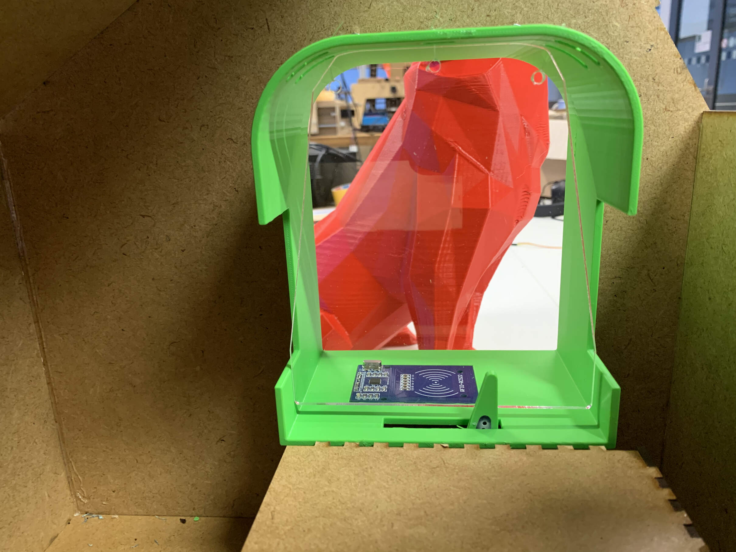
Regarding the cat house wireing, I sldered the RFID and servo wires to their respective connections on the PCB, this is housed in a little box that goes under the cat door tunel.
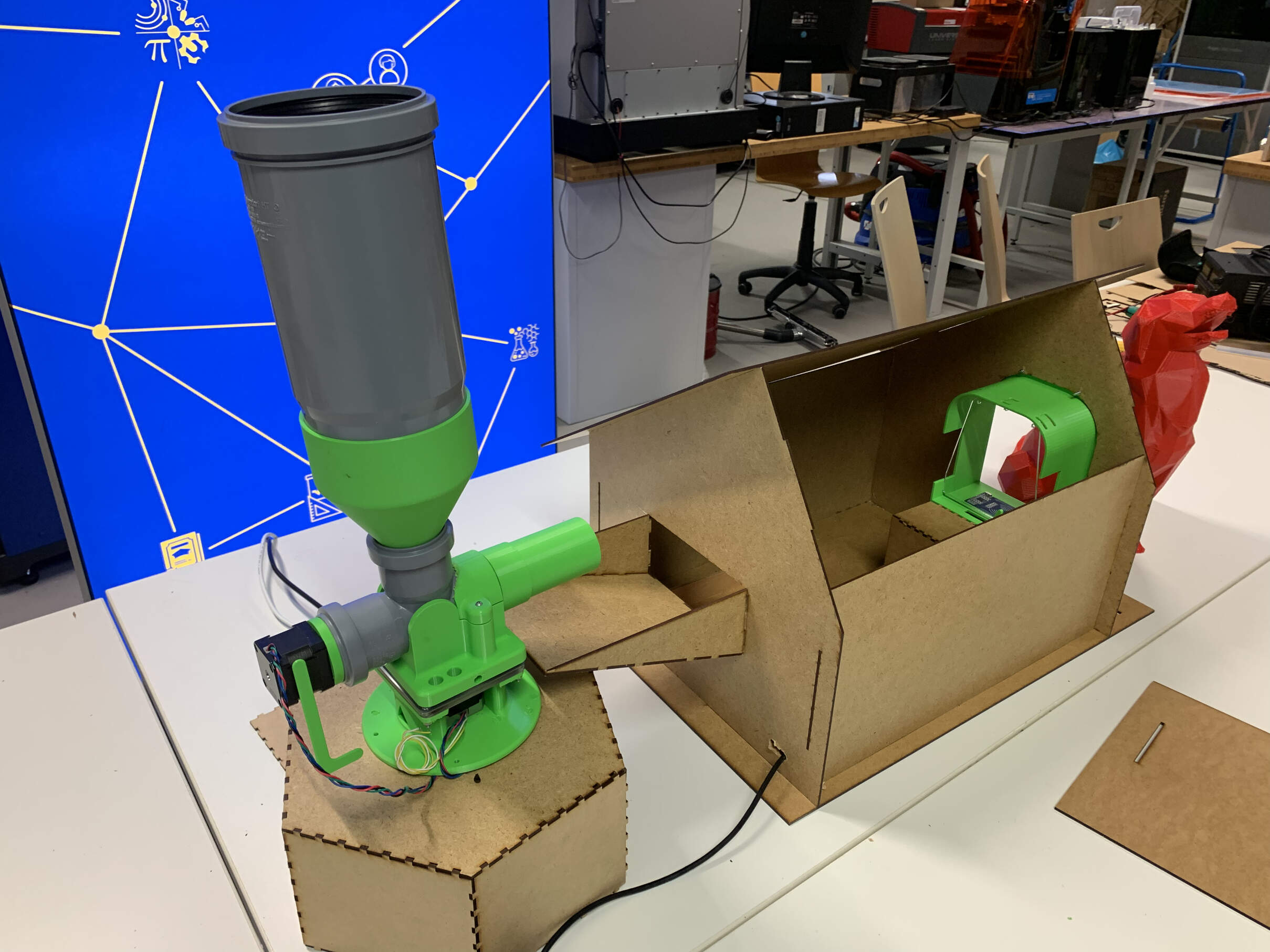
the main structure stands on a hexagon box, with holes att the top that allow the wires to go through. The screw stepper motor has a long wire to allow the base motor spin around towards each cat house
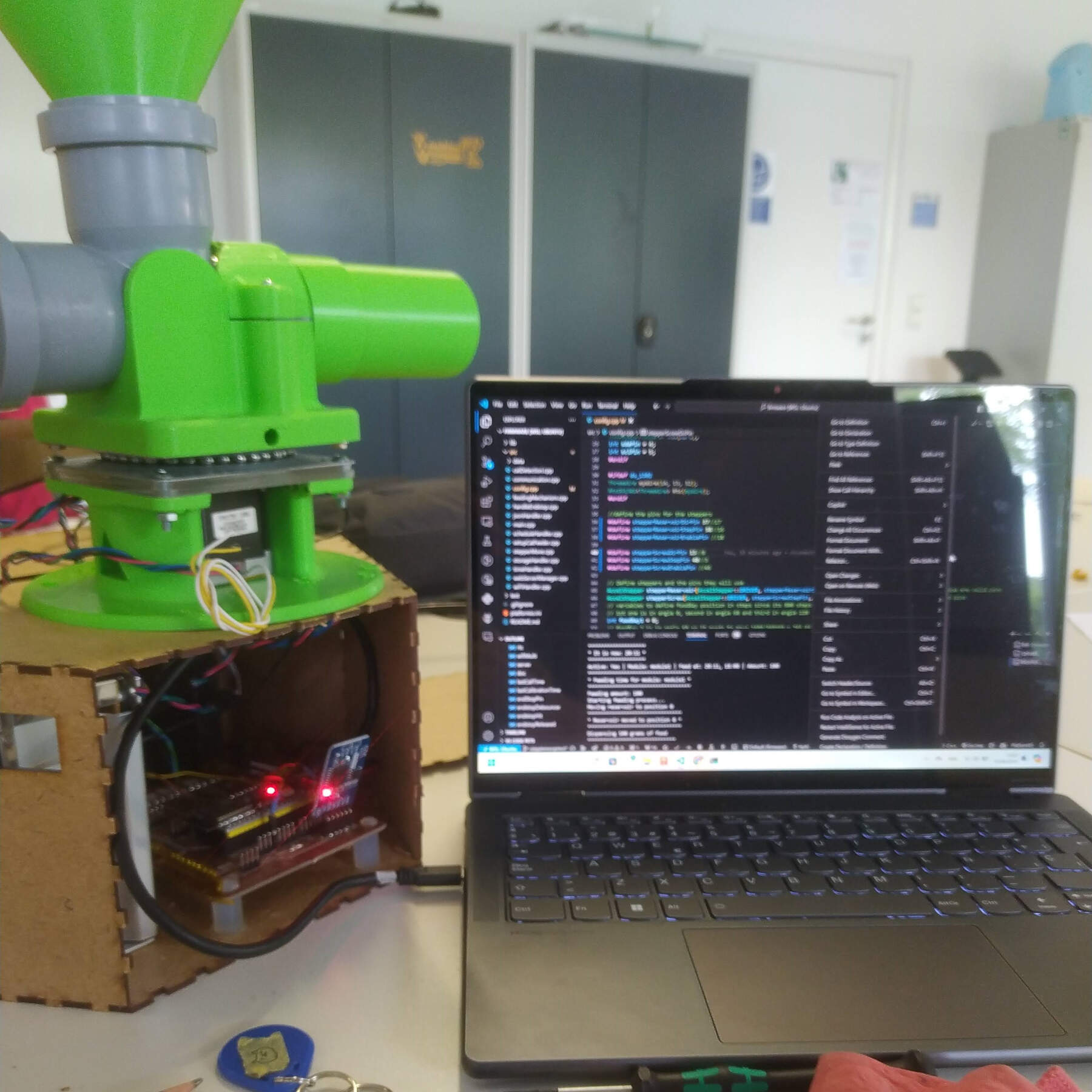
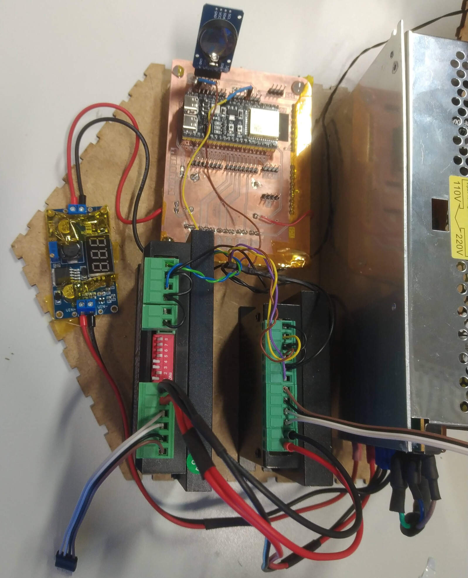
Inside the box there is the pcb, two stepper driveres and the power supply.
Here I can open one of the side to access the pcb for editing the code or changing the wiring
This is what the inside looks like.
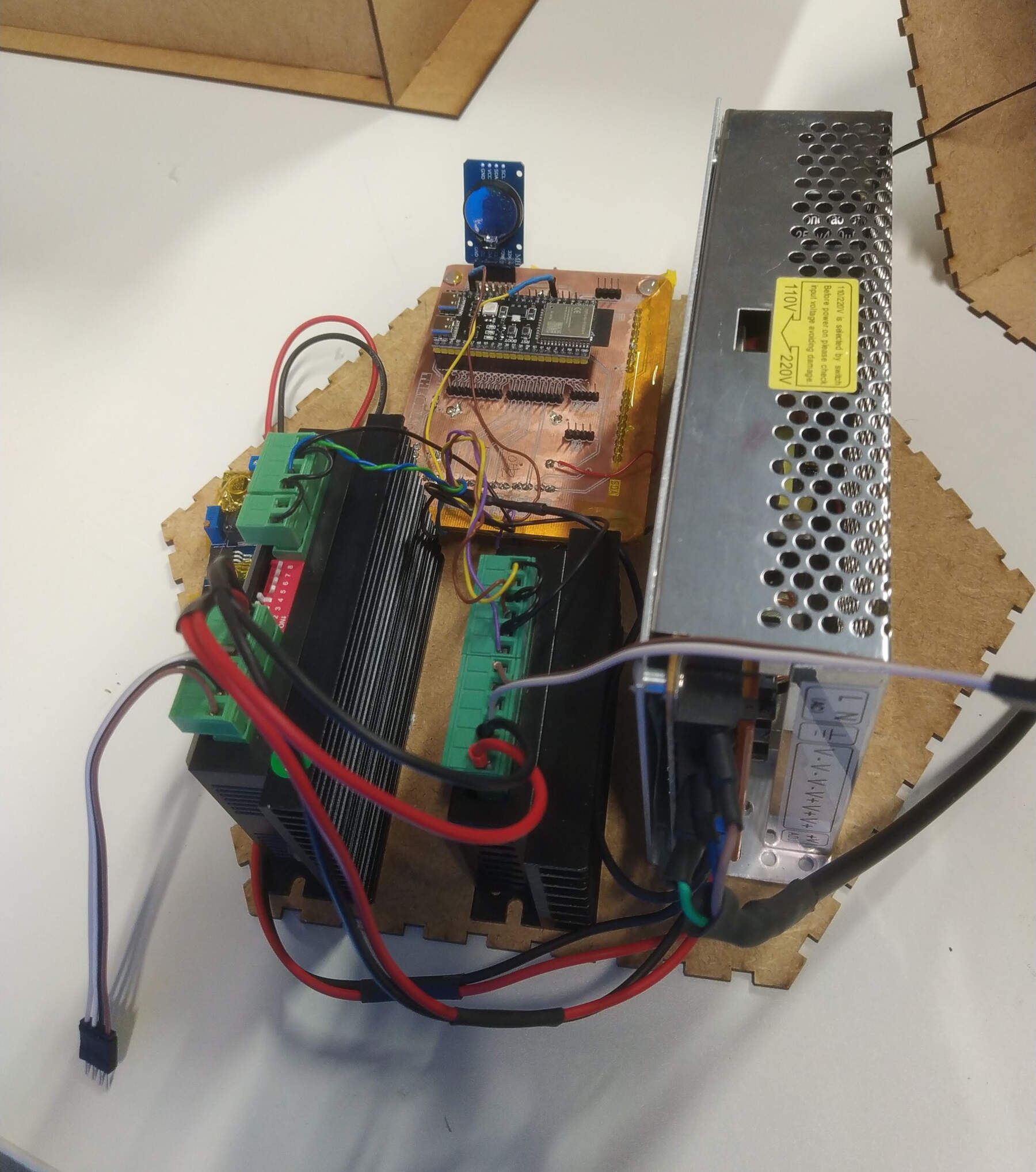
The connections goes as follows:
- MOTOR CONNECTIONS the step and dir wires comming from the pcb from their respective assigned pins connect to the step and dir on the two stepper drivers, on the drivers the gnds are all connected together, and from the drivers 4 wires go to each the stepper motorS.
- RTC the RTC simply connects to the pcb, the gnd, vcc, sda and scl pins are wired to their respective pins on the pcb
- DC BUCK CONVERTER the buck converter 4 connections, vcc in and gnd in are connected to the power supply, and vcc out and gnd out are connected to the pcb
- POWER SUPPLY the power supply is connected to the pcb, through the buck converter, the power supply is connected to the wall outlet
- The gate keeperThe gate keeper while it´s hard coded, has its GND and 5v connected to the pcb, however when I reprogram it to work via I2C it will be connected to the I2C pins on the pcb, there are several screw terminals for this I2C connection
Anyways have you ever had to transport a suitcase full of electronics? it´s a pain