Group assignment
For this week's group assignment, we were tasked with reviewing the safety data sheets for each of our molding and casting materials, then making and comparing test casts with each of them.
NEUKADUR PROTOCAST 105 Data sheet review
Main characteristics:
- Very good flowability
- Very impact resistant
- Very good colorability
- High heat resistance
- Cures to white color
- Only suitable for vacuum casting
| Component |
Color |
Mixing Ratio by Weight |
Density (20°C) g/cm³ |
Viscosity (25°C) mPa∙s |
| NEUKADUR ProtoCast 105 Component A |
Slightly yellowish |
100 |
1.05 |
650 |
| NEUKADUR ProtoCast 105 Component B |
Slightly yellowish |
200 |
1.16 |
160 |
| Mixture Properties (approximate values) |
PC 105 A / PC 105 B |
| Mixing Viscosity (25°C) mPa∙s |
325 |
| Density (20°C) g/cm³ DIN 53479 |
1.13 |
| Processing Time (25°C) Minutes |
5 |
| Demolding Time (70°C) Minutes |
60 |
| Hardness Shore D DIN 53505 after storage 2 Hours at 70°C |
82 |
| Cured Color |
White |
| Recommended Layer Thickness mm |
5 |
processing:
"NEUKADUR ProtoCast 105 Component A has to be homogenized thoroughly prior to processing. Tightly close receptacles
after every use. After 30 – 60 minutes, the cured material has not yet got its full impact strength (the same is only obtained
after approx. 1 - 2 hours at 70 °C) so that demoulding should be made with care, particularly when it deals with thin parts.
We recommend pouring NEUKADUR ProtoCast 105 Comp. A/B into moulds having been preheated to 70°C (e. g. of ProtoSil
RTV 240) and tempering the compound for at least 1 hour at 70°C before demoulding. Recommended thickness of cast layer:
up to max. 5 mm
Furthermore, we recommend evacuating NEUKADUR ProtoCast 105 Comp. A for 15 minutes at the highest possible vacuum,
then releasing the same to 20 – 25 mbar before adding NEUKADUR ProtoCast 105 Comp. B. At < 20 mbar, heavy foaming may
occur at the moment when both components are poured together."
PROTOSIL RTV 245
Main characteristics:
- Shore hardness A 40
- very good flow properties, translucent
- shrinkage-free vulcanization at room temperature
- can be made thixotropic
- high resistance to initial tearing and tear propagation
| Properties in the non-crosslinked state |
ProtoSil RTV 245 Comp. A |
ProtoSil RTV 245 Comp. B 1
(dry surface) |
ProtoSil RTV 245 Comp. B 2
(oily surface) |
NEUKASIL Thixotropic Agent SN 200 |
| Colour |
colourless |
colourless |
colourless |
colourless |
| Mixing ratio p.b.w. |
100 |
10 |
10 |
0.1 – 0.3 |
| Density 20 °C (approx.) g/cm3 |
1.1 |
0.95 |
0.96 |
0.98 |
| Viscosity 20 °C (approx.) mPa·s |
60,000 |
320 |
400 |
1,000 |
| Properties of the mixture (approx. values) |
Mixture A/B |
| Mixed viscosity |
35,000 mPa·s |
| Pot life (1000 g) |
80 minutes |
| Demouldable after |
12 hours |
| Shore A hardness points |
DIN 53505 40 |
| Service temperature |
200 °C |
processing:
See that as little air as possible gets into the compound while stirring. To obtain a bubble-free vulcanized material, we
recommend evacuating the crosslinker-containing formulation before continuing the processing.
When the vacuum is created, the mixture may expand by 3 - 4 times of its original volume under formation of bubbles.
The process is finished when the bubbles have collapsed and the formulation has reobtained its original volume.
Carefully pour the prepared material over the object to be cast
Here is a link to the group assignment page.
Individual Assignments:

For this week's assignment, I wanted to make a ring. Originally, I wanted to cast the ring in metal.
However, although we have a kiln at the lab, we are currently unable to use it.
This made me rethink the ring design, as my original ideas would not look good in resin.
With this in mind, I found this cool ring idea where you can connect Lego pieces to it.
Ring Design
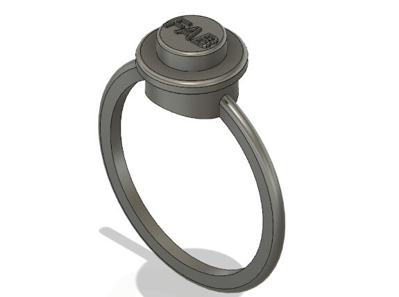
I went through two other ring designs before i setted on the final one, a 1x2 lego block and a 1x1 lego stud ring, however these designs were too small and would be quite challenging to cast properly
To start, I measured a ring I already had with a caliper to get the right size.
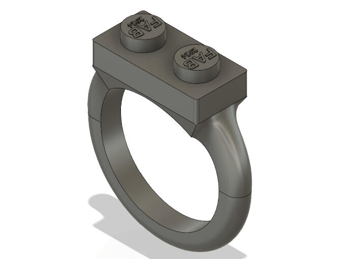
Then, I designed the ring in Fusion 360 following a Youtube totorial, and the steps below:

To measure the ring size, I used a caliper and an existing ring. The measurement I obtained was 17.6mm, which corresponds to the inner diameter of the ring.

In Fusion 360, I created a sketch that is divided into two parts: top and bottom. The bottom part is slightly larger than the inner diameter, while the top part serves as the Lego connection. I separated them this way because I will use two different tools to create the body.

Next, I created a sketch at the top in the shape of a square, following Lego dimensions (16 x 16mm).
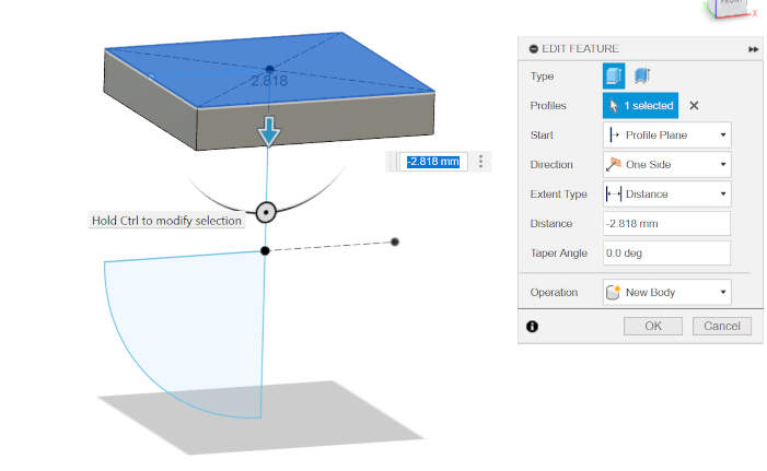
I then extruded the square downwards by -2.8mm to create the Lego base at the top.
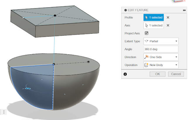
For the next step, I created a "revolve" using the sketch of the arc as the profile and the center line as an axis. This resulted in half a sphere.
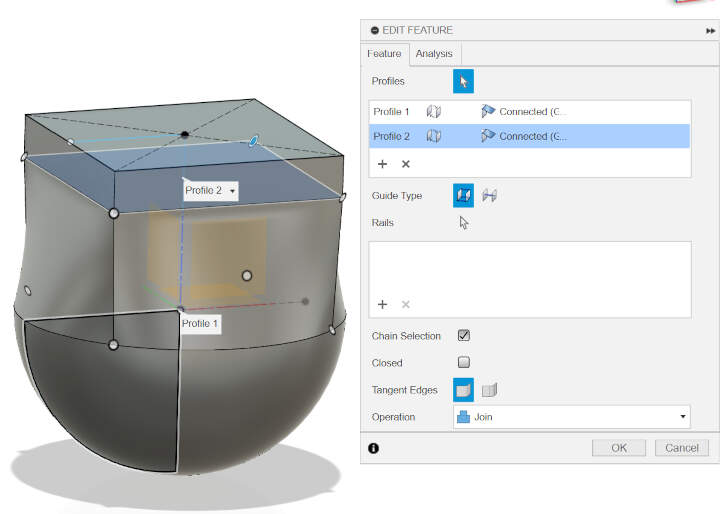
Finally, I created a loft by selecting the bottom surface of the square and the surface of the half sphere.
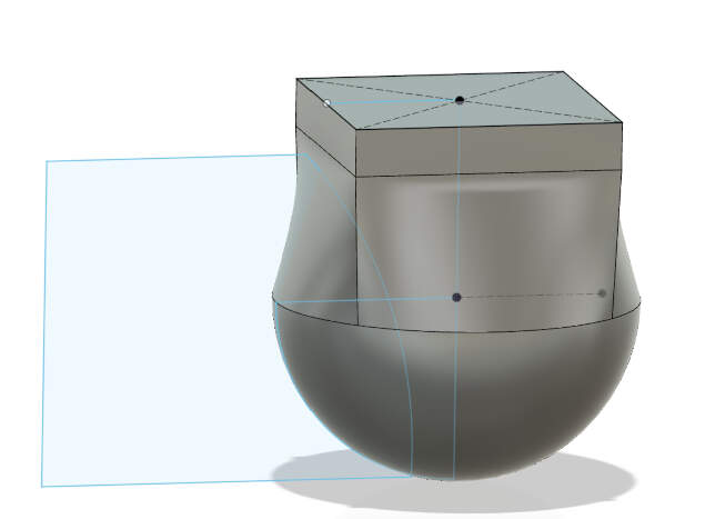
To carve out the side profile shape of the ring, I created a new sketch of half an arc. Then, I extruded this shape symmetrically on both sides and chose the option to "cut."
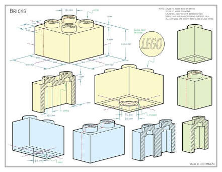
I used this technical drawing of a Lego brick to help me with the dimensions and design of the Lego attachment part of the ring.
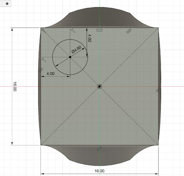
Create a sketch on top of the 16 x 16 square. Then, create a circle with a diameter of 4.8mm. To position this correctly, draw two construction lines. Use the dimension tool to select these lines and specify the distance to be 4mm.
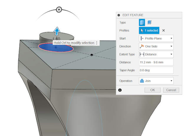
Extrude the circle to create the little knobs on a Lego block, following the Lego block specs. I went with 11.2mm (height of a Lego block + studs) - 9.6mm (height of a Lego block without studs).
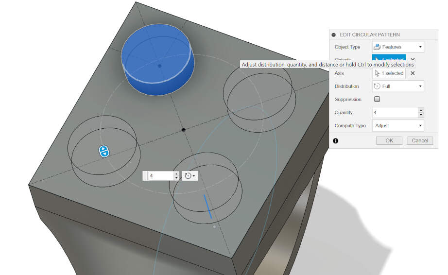
To create the other 3 studs, I created a circular pattern and selected the first stud as a feature, and then the line from the previous sketch as the z-axis.
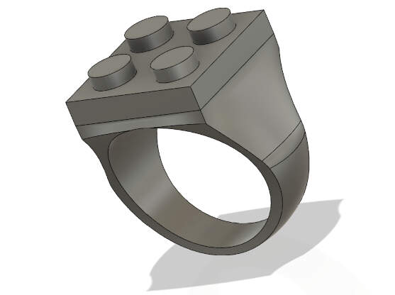
TA DA! A Lego ring ;)
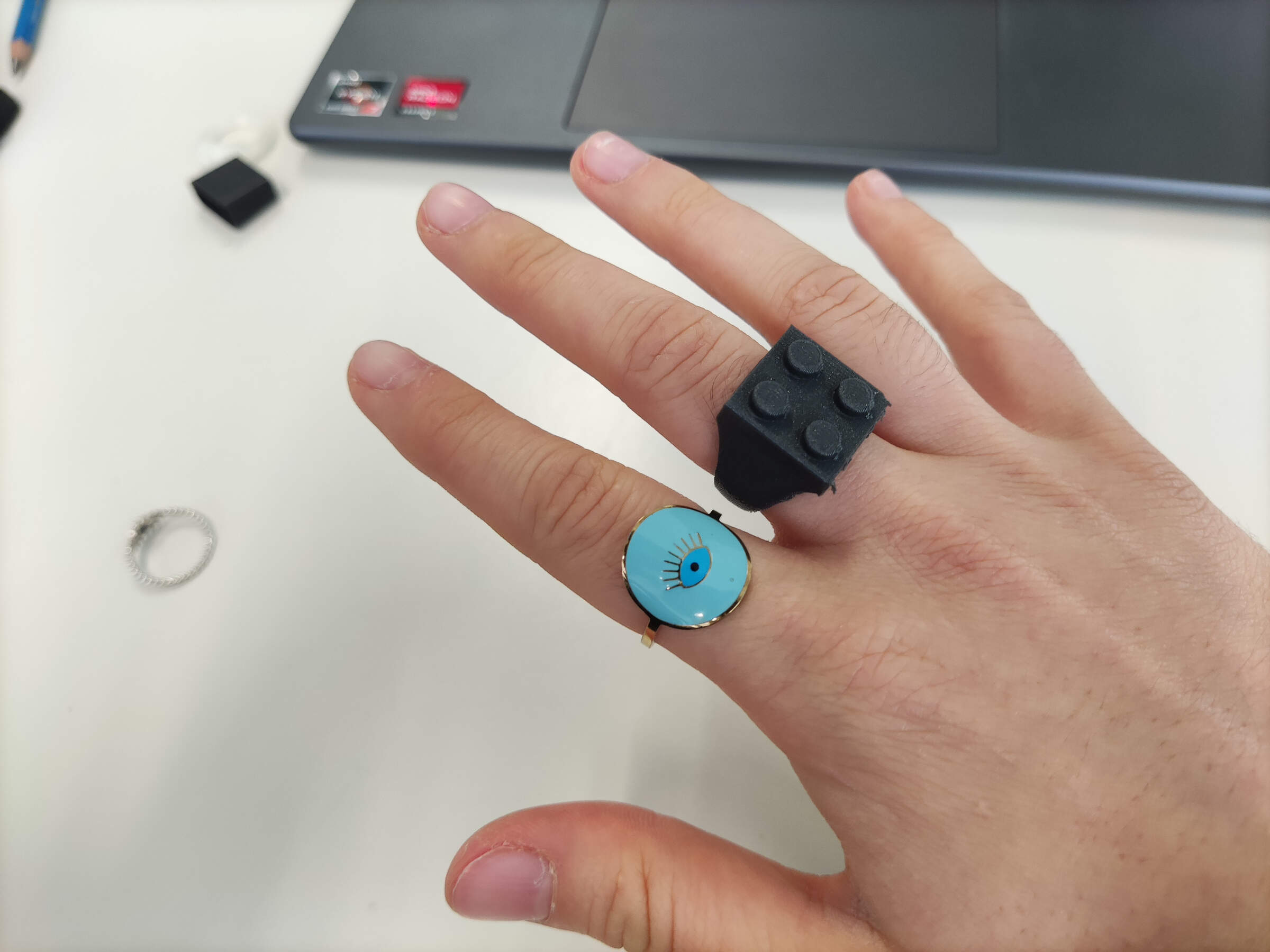
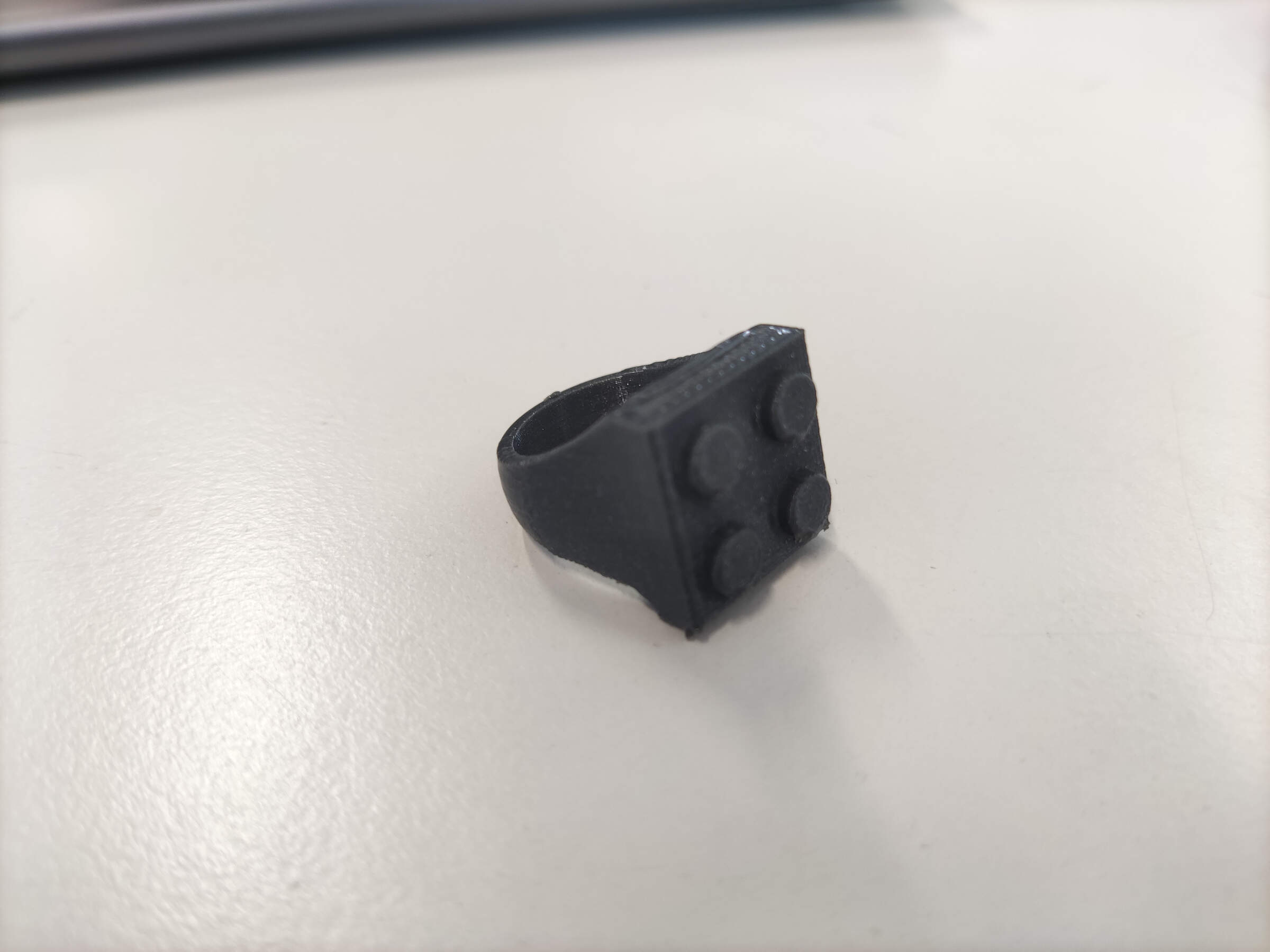
Before creating the mold, I made a test print of the ring to see if it fits.
For this, I didn't really care about the quality of the print, so I used the Ultimaker 3D printer and printed it with PLA.
and it came out great!
Mold Design
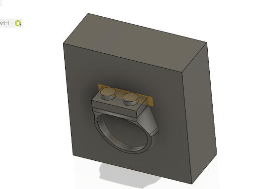
To design the mold, I created a new file on Fusion 360.
Then, I inserted the ring I designed as a component. From there, I created a mid plane on the ring and drew a square around it.
Next, I extruded the square to create the mold. After that, I used the combine tool to join the ring and the mold together.
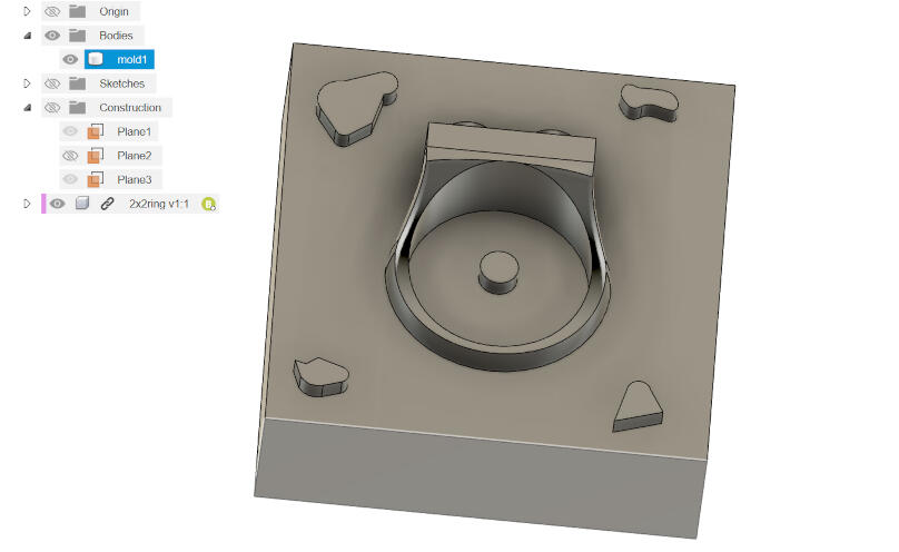
Then, I created 5 extruded shapes on the corners of the mold and one in the middle. These serve to secure the two parts together and prevent them from sliding.
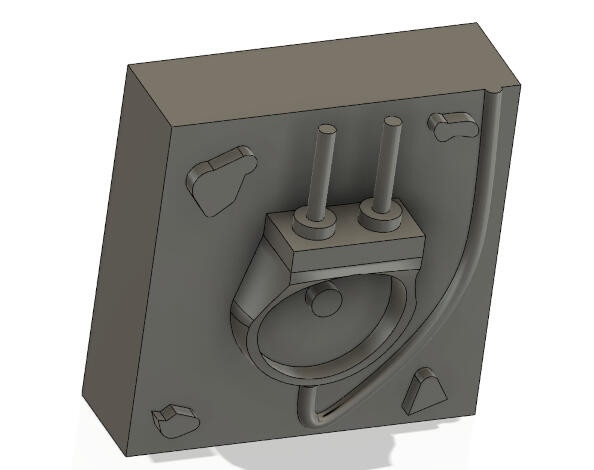
After some contemplation and with guidance from my instructor, I decided to place the feeding hole through one of the Lego studs and a vent on the other.
Additionally, to ensure there are no air bubbles in the mold and that the whole ring is filled in, I added an "overflow" at the bottom of the ring.
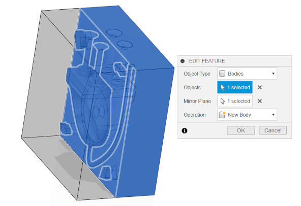
To create the second mold, I mirrored the first mold by selecting its body and using its surface as the mirror plane.
Then, I created a new body on this second part, I extruded the connector bits -4mm to make them into dents so they can fit into the first mold.
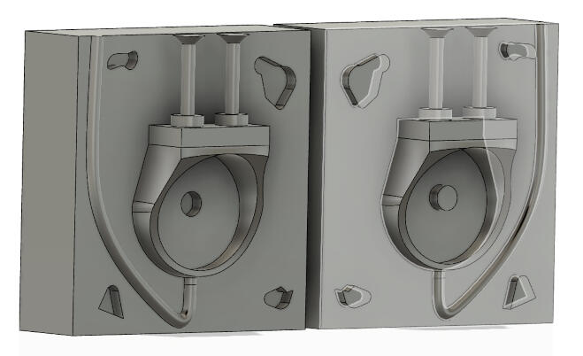
I will print this on the resin printer we have at the lab, and because of this, I didn´t design the walls, to save on resin and time. this means I´ll have to laser cut a box, when I cast the inverted molds
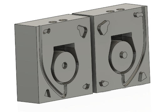
to be sure that the two molds would fit togehter properly and that the mirroring worked as i wanted it to, i made the inverted molds through these two parts, by extruding a block and then using the combine tool to cut the molds. the final verdict is that it will work!
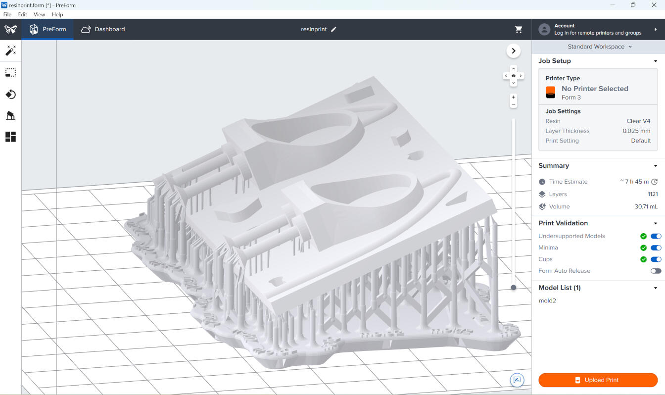
SLA Printing
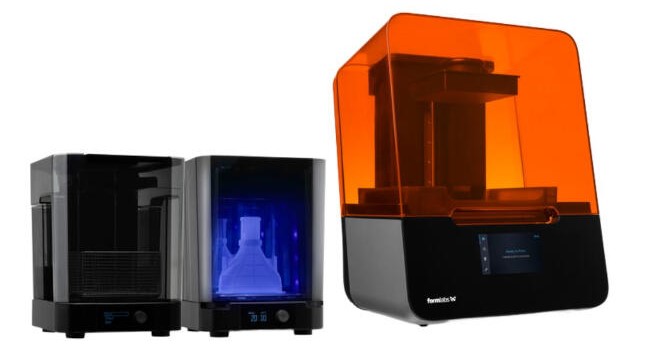
At the lab, we have a few resin printers, but the one I'll be using is the Form 3+ SLA printer by Formlabs. The slicer I used for this was Preform, and the settings I used were:
- Layer height: 0.025mm
- Resin: Clear v4
- Print settings: default
- Estumated print time: 7h 45min
I left this print overnight, and the next morning it was ready.
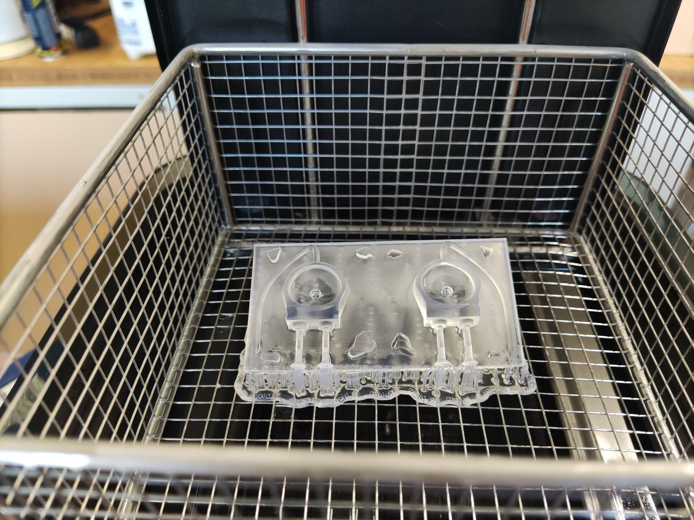
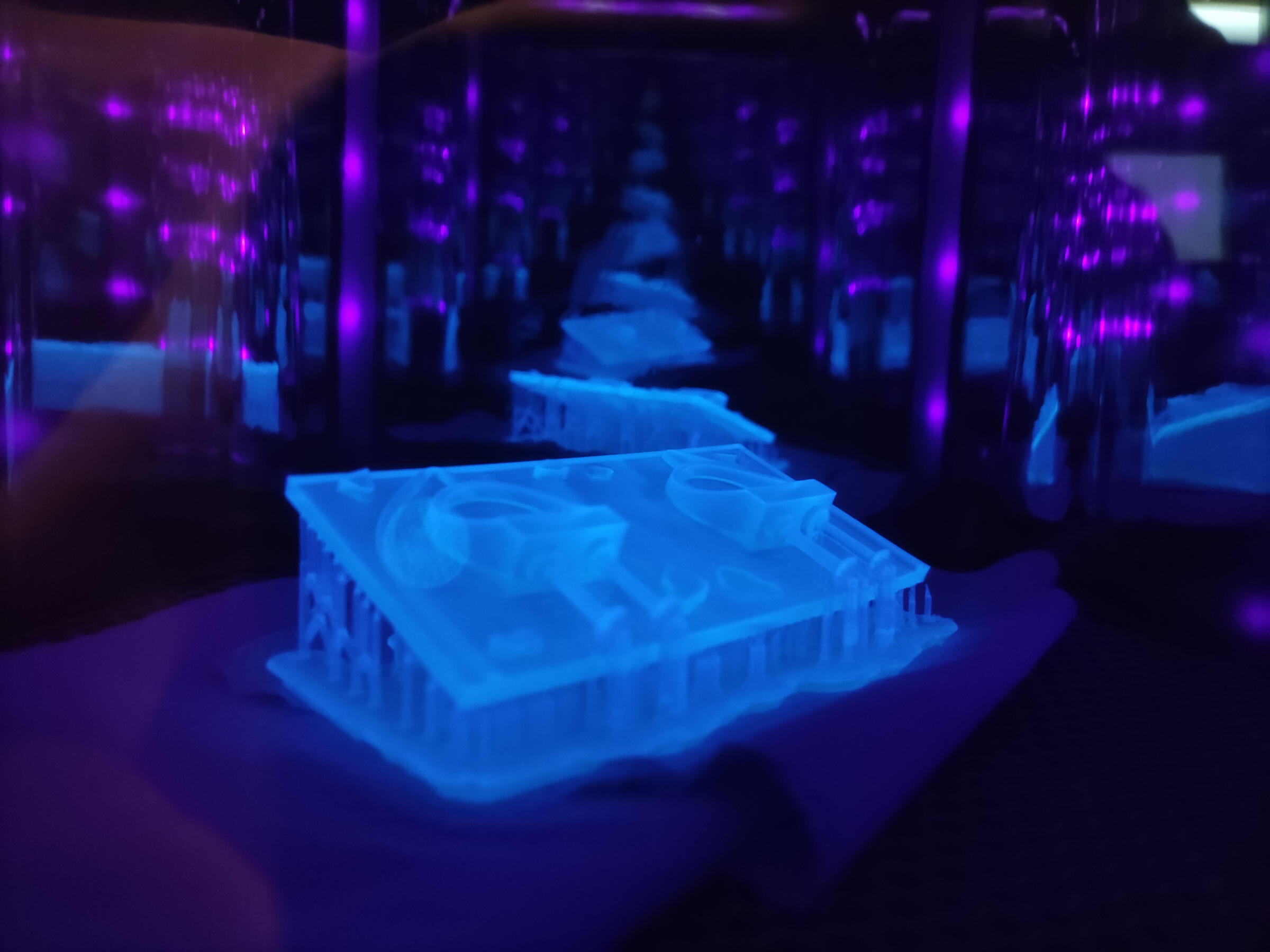
The final steps involved washing it in isopropyl alcohol and curing it under UV light.
At the lab, we have both a UV curing chamber and a wash station, so it was quite easy to do this.
Regarding the washing process, since the print is quite small, I left it in the washing station for about 30 minutes, and then cured it for an additional 30 minutes.
Lastly, I removed the supports, and the print was ready to be used.
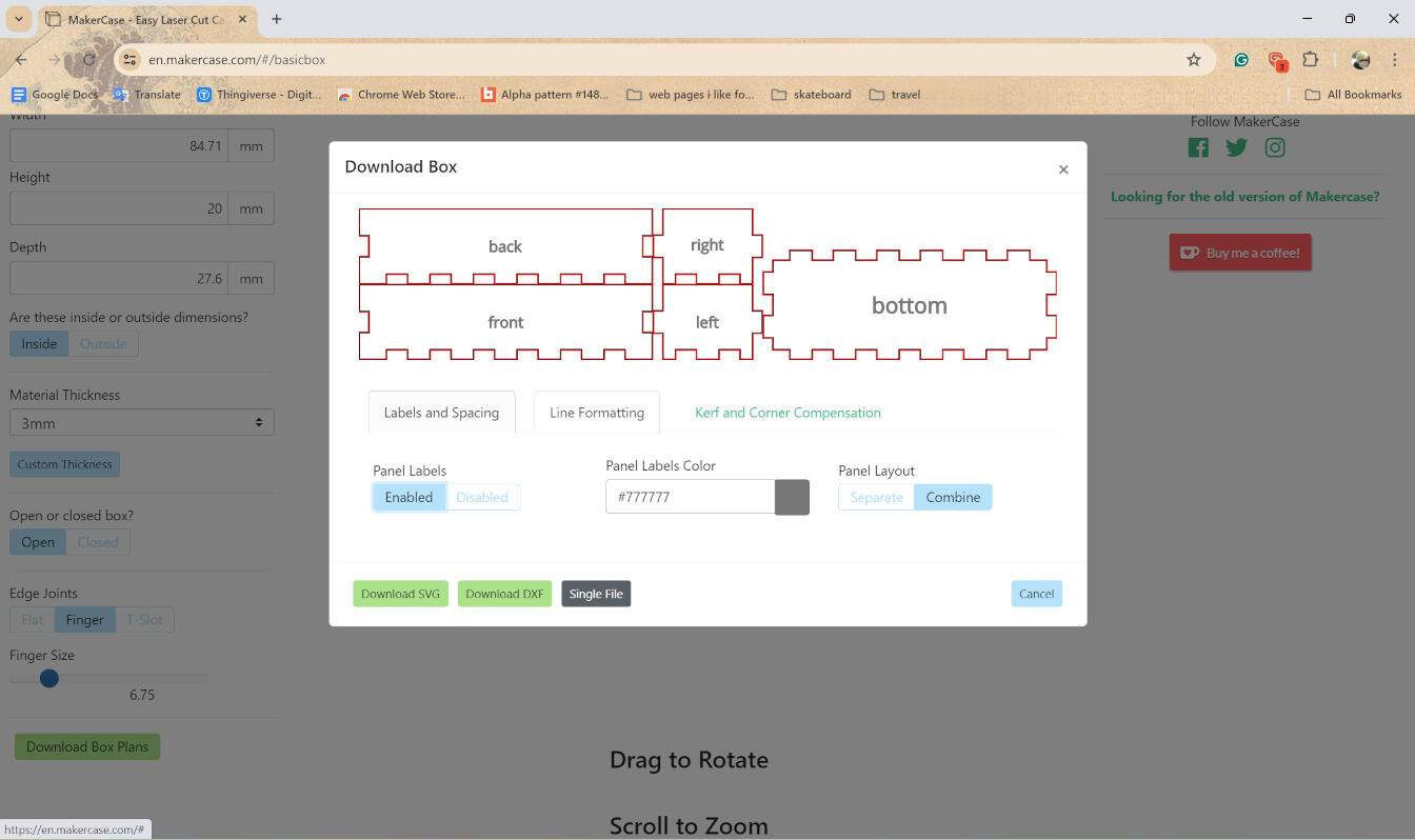
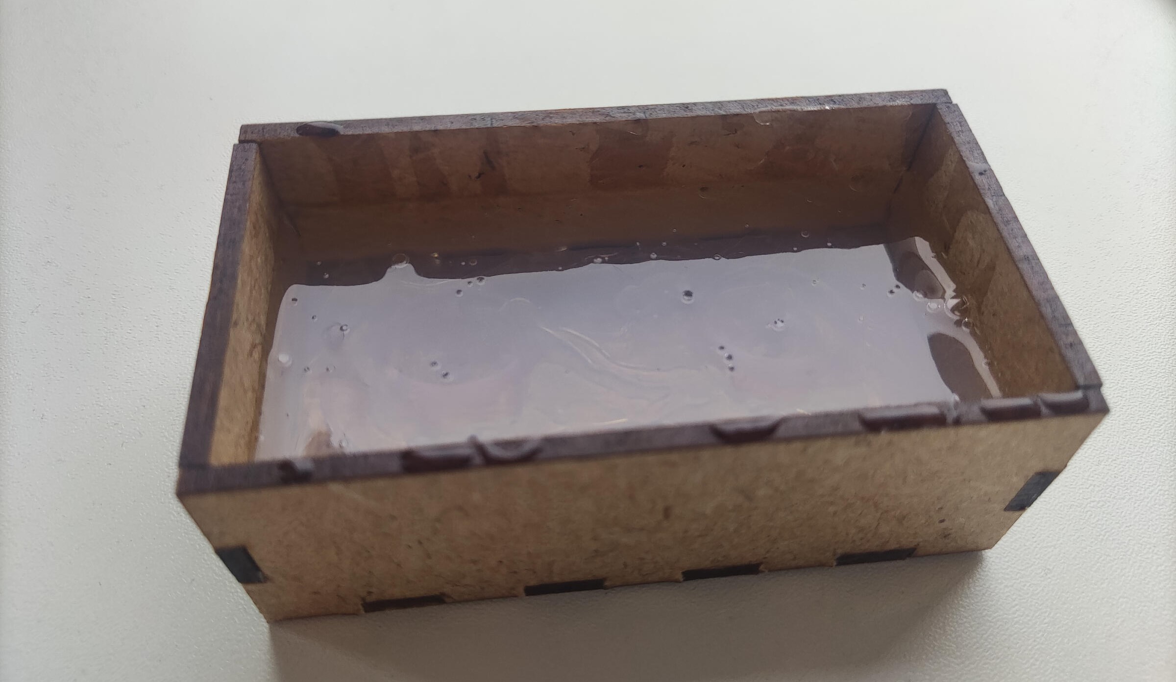
One more crucial step before casting is to make a box to hold the silicone.
For this, I use a site called makercase to generate the box.
Then, I laser cut it and added some tape around the edges to prevent the silicone from leaking out (the silicone we have at the lab is actually quite viscous, so it doesn't leak out that much, but this is a good practice to have).
Casting the negative mold
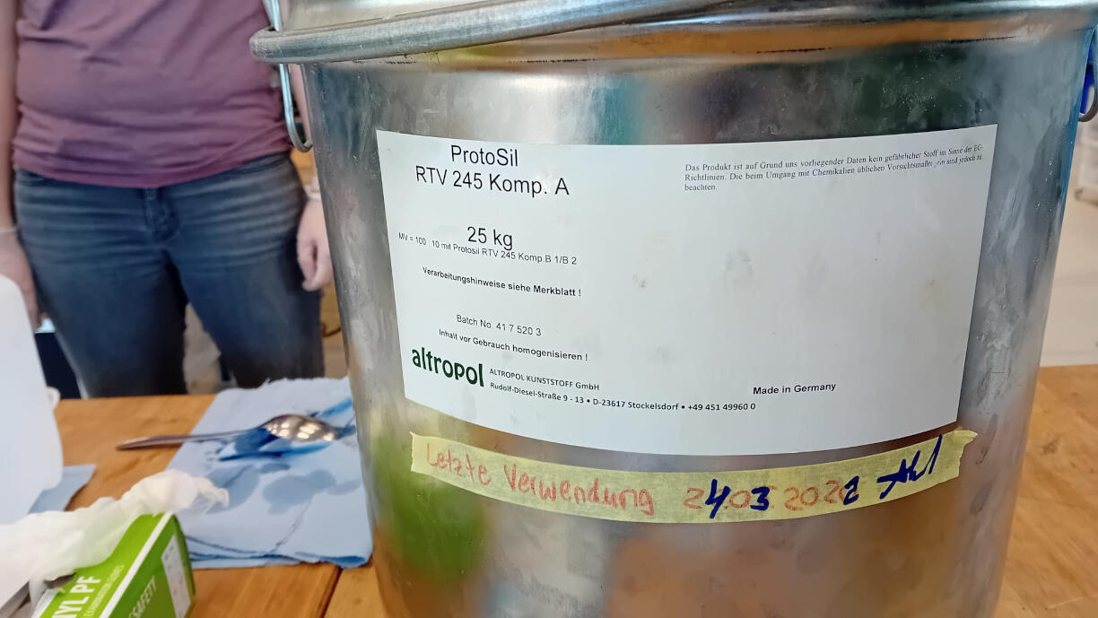
To create the negative mold, I used silicone. The one I'll be using is ProtoSil RTV 245 Komp. A and ProtoSil RTV 245 Komp. B1, which is a two-component silicone rubber. This part of the assignment was done in a group with the guidance of our instructor.
Datasheet info for mixing:
Minimize air incorporation during stirring.
To achieve a bubble-free vulcanized material, evacuate the crosslinker-containing formulation prior to processing.
Expect the mixture to expand 3-4 times its original volume and form bubbles during vacuum creation.
Processing is complete once the bubbles have collapsed and the mixture returns to its original volume.
Pour the prepared material over the object to be cast with care.
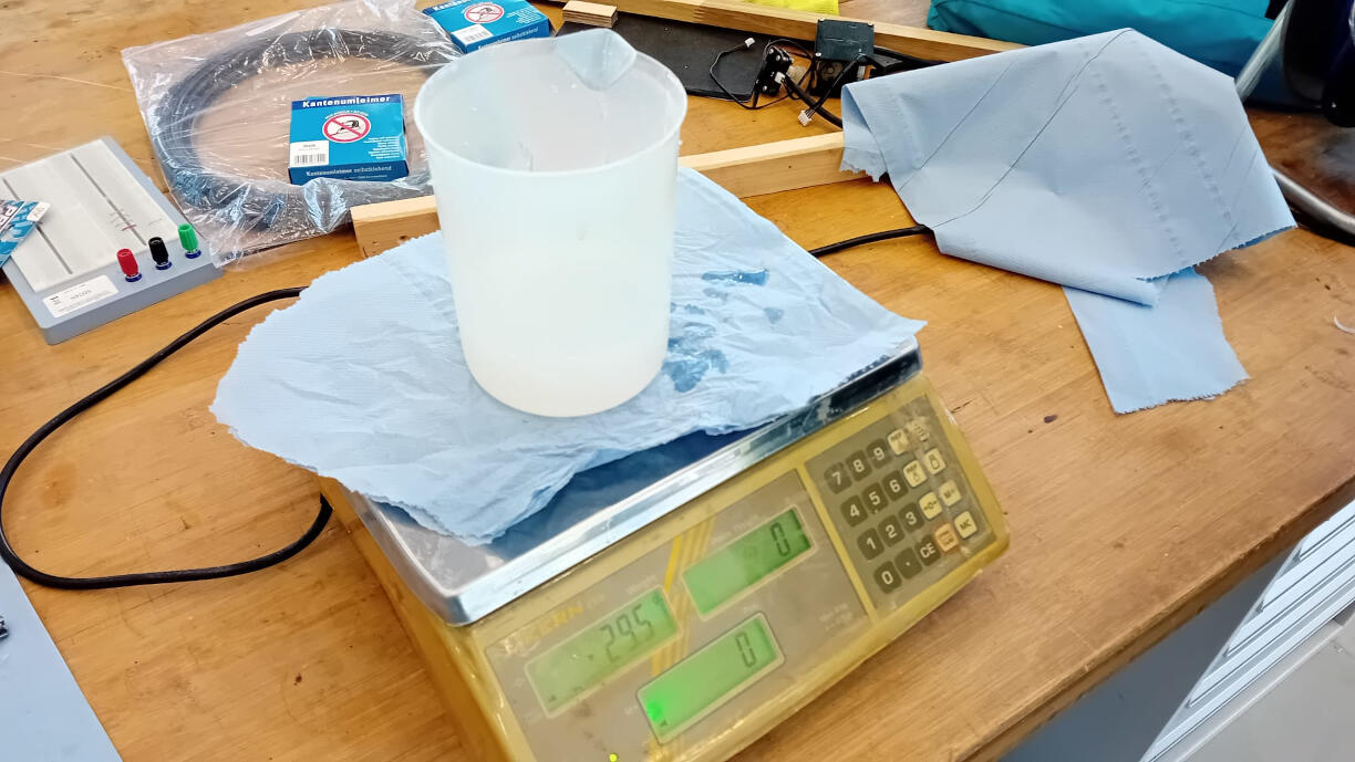
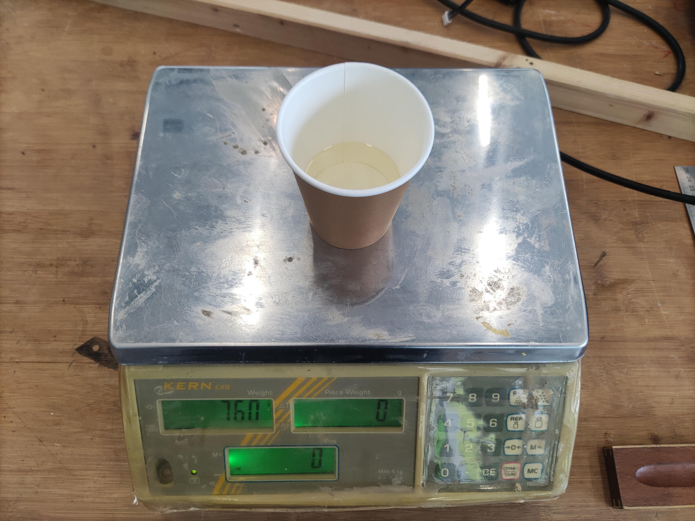
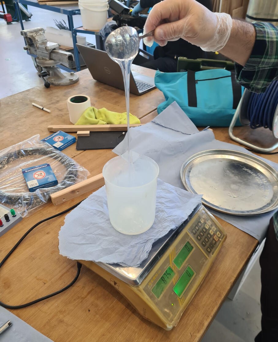
The mixing ratio of component A and B is 100:10. And to start, first measure component A and then add component B (these were measured in a special plastic container that does not react with the silicone).
According to the datasheet, the mixing process is best done in a vacuum environment.
However, our instructor gave us a tip to mix it a little bit before putting it in the vacuum chamber.
Something to note: it's important to clean the mixing tool and the container before mixing the two components,
as any residue can affect the curing process (this part is generally easy to do after waiting for any residue to cure, so that you can just peel it off).
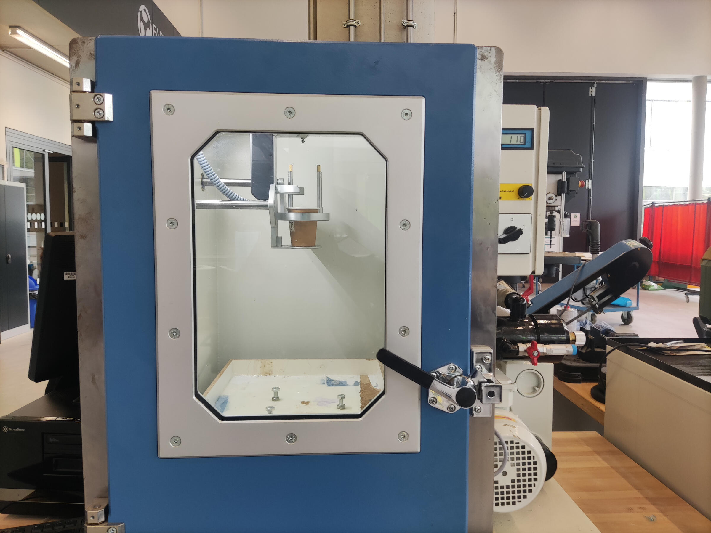
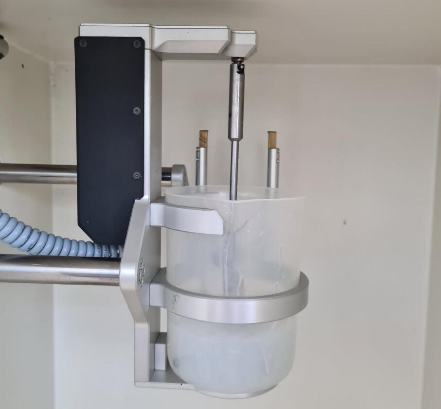
Using the vacuum chamber
Operating the vacuum chamber at the lab is pretty straightforward.
At the side of the machine, you turn the main switch to turn it on.
To start the vacuum process, you turn the knob at the front of the machine.
On a little monitor at the right, you can see the pressure of the chamber.
When it reaches the desired pressure, you can turn the knob back to stop the vacuum process.
The machine we have is quite good at holding the vacuum and usually only drops 1 to 2 bars of pressure over a longer period of time (this also depends on how clean the seals are).
Lastly, to release the vacuum, you turn a little red lever towards you and the pressure will be released (this is good to do slowly to avoid creating vortexes and getting any dust in your mix).
In the vacuum chamber, the mixing is best done with a varying pace because as the components mix, a reaction starts to happen and the mixture will start to expand.
So it's important to keep an eye on the mixture while doing this.
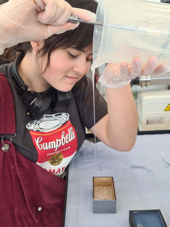
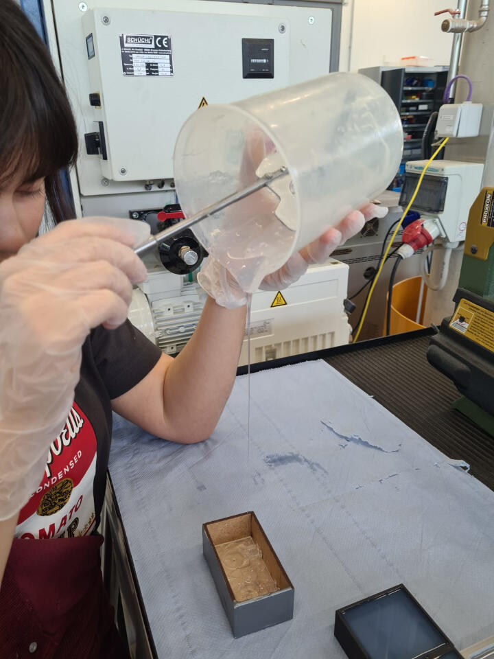
I poured the silicone into my mold, at first with a very small bead to get all of the more detailed parts, and then after these were covered, I went ahead with the rest of the silicone.
At first, there are quite a few bubbles, but as the mixture cures, these will rise to the top and pop, so it's important to not touch the silicone while it cures.
Because we did this part as a group, we also cast our negative molds together.
However, because my component only finished printing this morning, I did the curing process while we were also casting the molds.
This meant I cast mine a bit later than the others, and so the silicone had already started to cure a bit.
This is not ideal, especially because I think the silicone might have exceeded the pot life, but I'll have to wait and see how it turns out (I still went ahead with this just to see how it would cure).
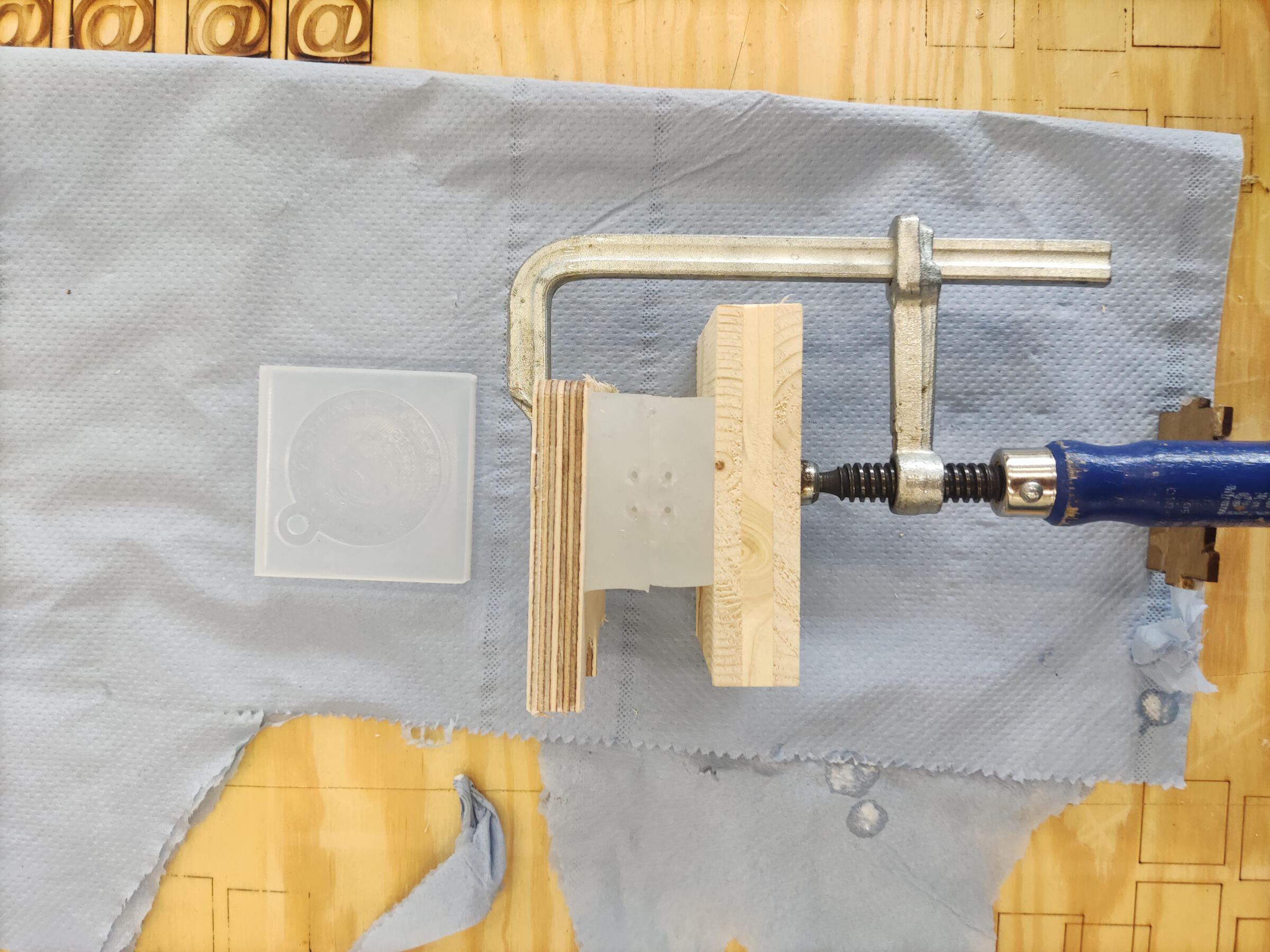
As you can see, there are still some bubbles in the silicone after it has set.
Thankfully, though, it wasn't as bad as I thought it would be, and the bubbles weren't in any critical parts of the mold, so I think it will be fine.
After it set compleatly I cut the mold in half and cleaned up the edges a bit
Casting the ring
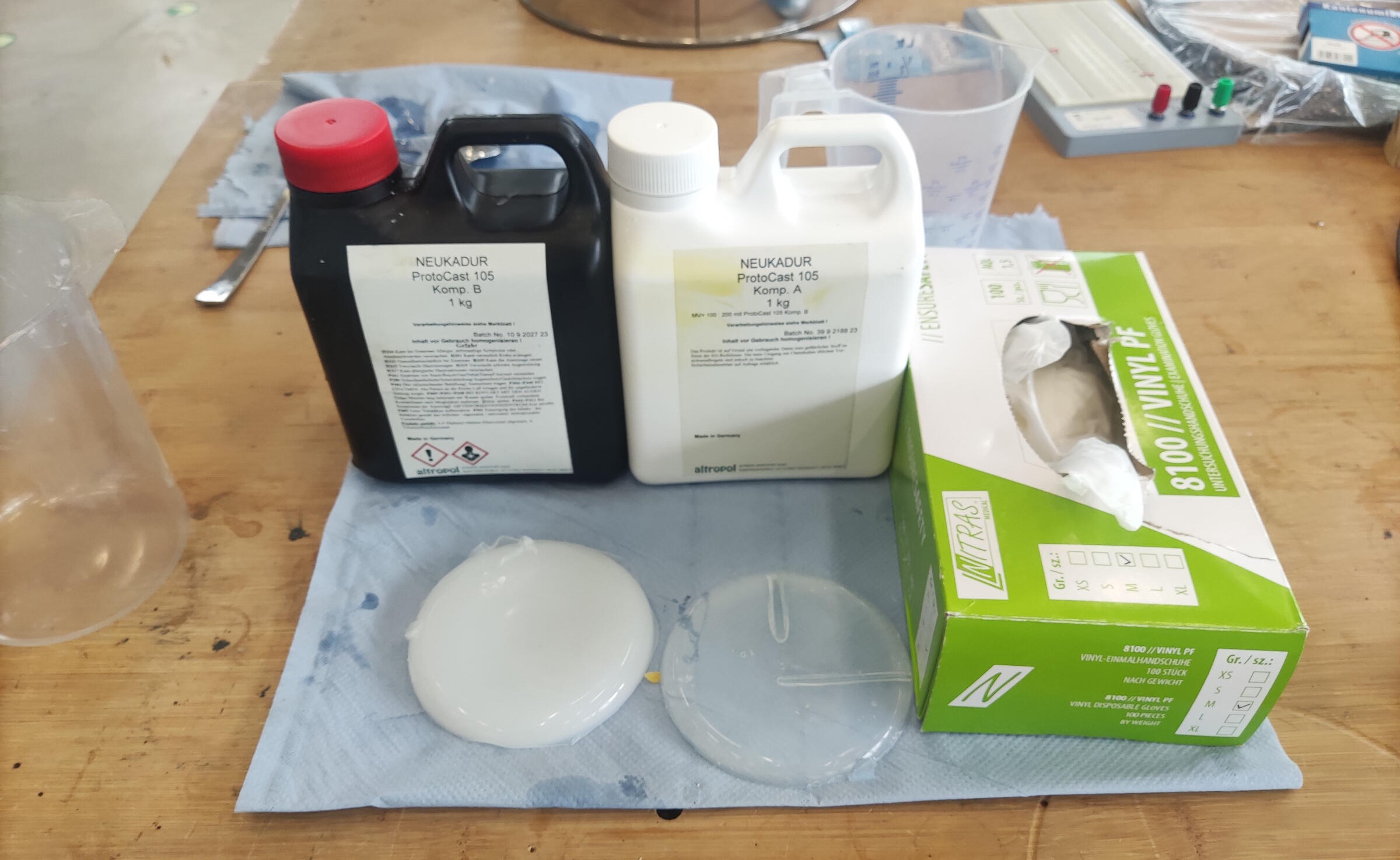
To cast the ring, I used a two-component resin called NEUKADUR ProtoCast 105. According to the datasheet, the mixing ratio is 100:200 (component A: component B).
The datasheet also instructs to remove the air from component A before mixing, so I put it in the vacuum chamber for a few minutes. Then, I added component B and mixed it. This resin is a bit tricky to work with because it reacts very quickly as it has a very short pot life of around 3 minutes. This means I had to be prepared to pour it as soon as it was mixed.
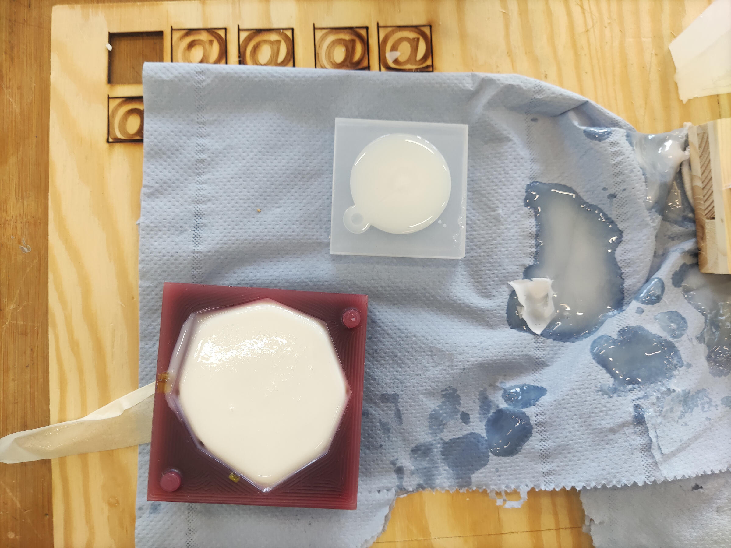
This was my "mixing station". I had a piece of wood and some paper towels covering the work table in case there was any spillage, and I had the molds ready to pour the resin into.
Originally, I planned on only casting my mold and the one we made for the group assignment. However, I had some resin left over, so I also casted a random mold I found in the lab from a previous Fab Academy student just to see how it would turn out.
Results
LEGO ring
This was very tricky to pour because the resin is very viscous and the mold is very small. As I tried to pour it in, it would overflow, blocking the vent and not letting the air escape. Then, I would try to wipe off the excess and pour more, but it would overflow again. And because this is a fast-acting resin, the pouring channels were already starting to cure, so I couldn't even try to pour it again to fill in the rest.
I was already expecting something like this to happen, so this was just a test run.
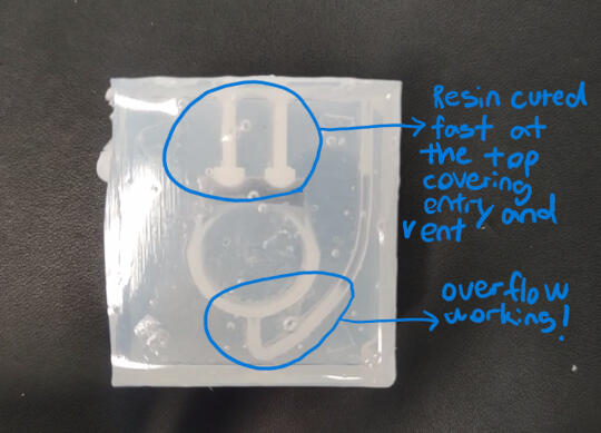
Autopsy of the ring
When I opened up the mold after the resin finished curing, I was actually pleasantly surprised by what I saw. Yes, it was a failure, but it was a very interesting failure. This was because some resin was able to get in, and the overflow I designed was working as intended! This meant that the mold works, I just need to work on the pouring process. My idea is to use a pipette to pour the resin in a more controlled way.
Key ring
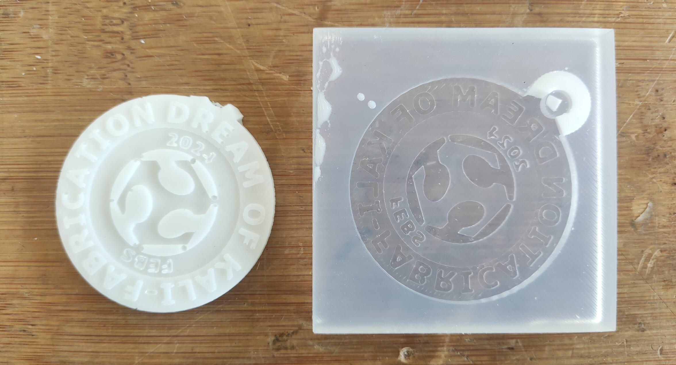
As shown in the image, there are areas where the resin didn't get into, and then the ring bit was quite brittle and broke when I tried to remove it from the mold.
Random mold
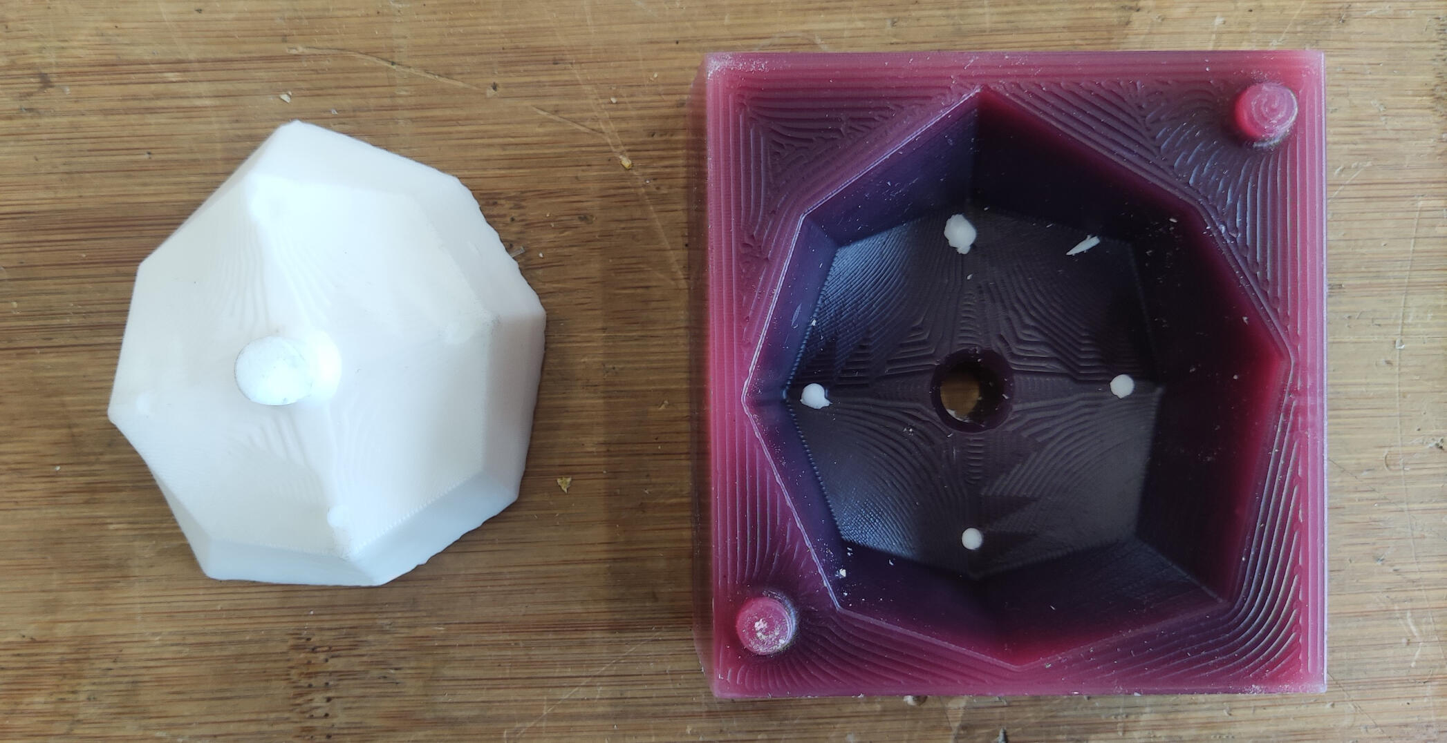
This came out great! The resin got into all the details and cured without any bubbles or deformations, and perfectly showed all of the details and textures of the mold (which was milled on the Roland mill).