- Send a message between two projects
- Design, build, and connect wired or wireless node(s) with network or bus addresses and local input &/or output device(s)
FABACADEMY
FABACADEMY

More cat content, you can see why he needs the cat feeder ;p
Here is a link to the group assignment page.
This week's assignment consists of making two or more PCBs communicate through different protocols.
Reflecting on how I could use this week to progress on my final project, I remembered during Neil's lecture on Wednesday that he mentioned that using a communication protocol can simplify and help make a project modular. Originally, I planned to make my project modular by simply connecting everything to the main board. However, I didn't fully consider the pin limitation of the main board (which would pose a problem because the RFID reader uses up 7 pins). So, I decided to use this week to help me solve this modularity issue.
By making smaller secondary boards that would communicate with the main board through I2C, I could make the project more modular and easier to assemble.
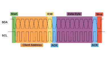
This is a question I still asked myself even after Neil's lecture, so I decided to do some research on the topic to better understand how this protocol works. I2C stands for Inter-Integrated Circuit, and it is a synchronous, single-ended, short-distance, serial communication protocol that uses two lines: one for data (SDA) and one for the clock (SCL). The I2C protocol was invented by Philips in the 1980s, and it is widely used in the industry. One example of its use in our daily lives is how some smoke alarms communicate with each other using the I2C protocol.
I2C communication is a multi-controller/multi-target protocol, meaning that the main board can communicate with multiple secondary boards and vice versa. The data being communicated is sent in the form of a 9-bit packet, which has the following sequence: a start condition, the secondary device address, a read/write bit, an acknowledge bit, the data being sent, another acknowledge bit, and finally a stop condition.
In the idle state, both SDA and SCL are high. The start condition occurs when a node first pulls SDA low and then pulls SCL low. This "claims the bus," meaning that the node is now the main and prevents other nodes from sending data at the same time (taking control of the bus). Now, the main can start sending data to the secondary nodes.
The second part of the byte sent is the address of the secondary node. This is a 7-bit address that is unique to each secondary node. The 8th bit is the read/write bit (R/W). If the bit is 1, the main is sending data to the secondary node. If the bit is 0, the main is reading data from the secondary node.
After the address is sent, the secondary node sends an acknowledge bit (ACK bit), which is a 9th bit sent by the secondary node to confirm that it is ready to receive or send data.
After the ACK bit is sent, the data is sent. This is an 8-bit packet sent by the main to the secondary node. Usually, the MSB (most significant bit) is sent first. After the data is sent, the secondary node sends another ACK bit to confirm that the data was received (this part is always followed by an ACK bit).Lastly, the main sends a stop condition, which indicates the end of data bytes. This happens when SCL goes (and remains) high first, and then SDA goes (and remains) high. This means that the bus becomes idle, and other nodes can now claim the bus. However, in some cases, the secondary boards are programmed to never be able to claim the bus.
In an I2C circuit, the SDA and SCL lines from the secondary nodes are pulled and connected to the main board through pull-up resistors. This is done to prevent the lines from floating when the nodes are not sending data. Usually, the pull-up resistors have a value that ranges from 1kΩ to 10kΩ.
When choosing the pull-up resistors, it is good to check your microcontroller's datasheet and consider what you need for your application.
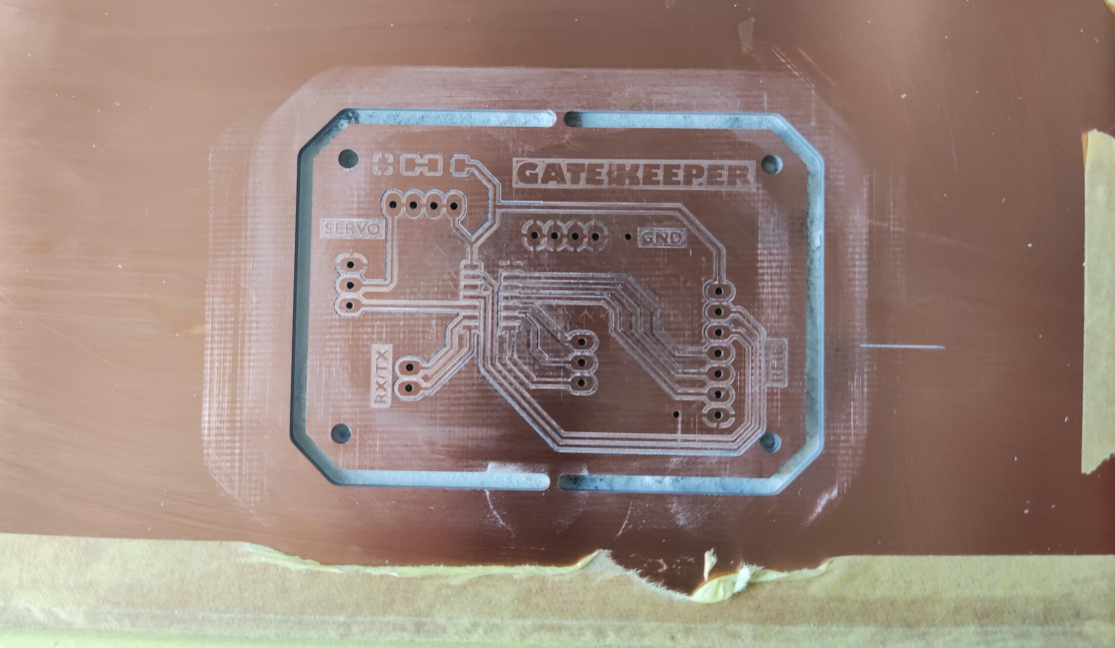
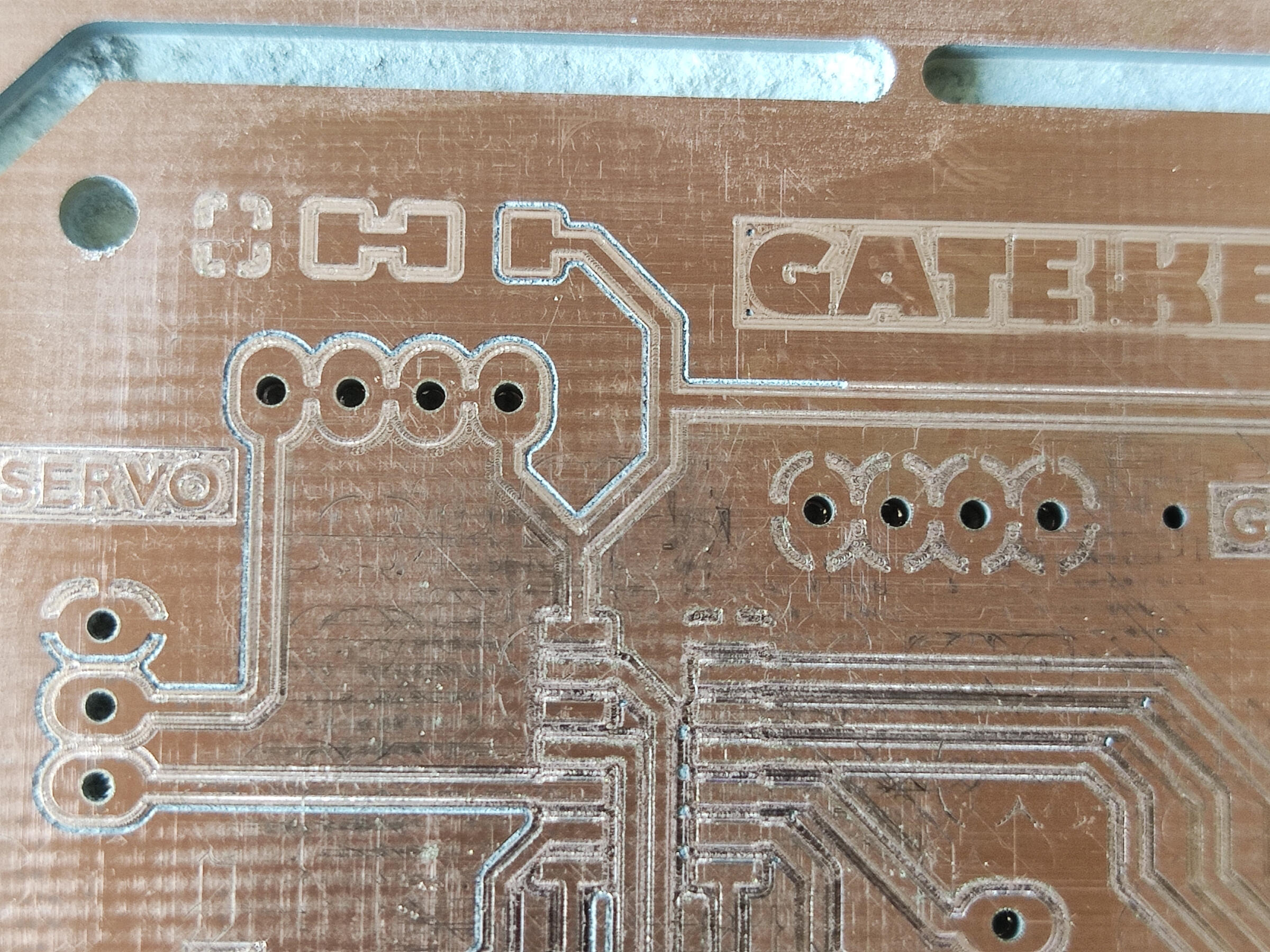
After understanding how the I2C protocol works, I started designing the secondary boards that would communicate with the main board.
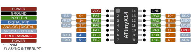
I decided on using a attiny16 microcontroller for the secondary boards because it has 8 pins, which is enough for the I2C communication and the input/output (RFID and servo) devices I want to connect to it. On paper I started planning what this boards requiresments would be:
| Component | Pins |
|---|---|
| pins for I2C communication (SDA and SCL) | pin 8(A6) and 9(A7) |
| pins for the RFID reader | RST(pin4, A2), SDA(pin2, A0), MISO(pin13, A10), MOSI(pin12, A9),VCC,GND |
| pins for the servo motor | pin 5 (A3) |
| power LED | connected to VCC |
| UPDI pin for programming | pin 10 (A11) |
| rx and tx pins | pin 6 (A4) and 7 (A5) |
Since the original SDA pin was being used for the main I2C communication, for the RFID reader, I used a random analog pin which was pin 2 (A0).
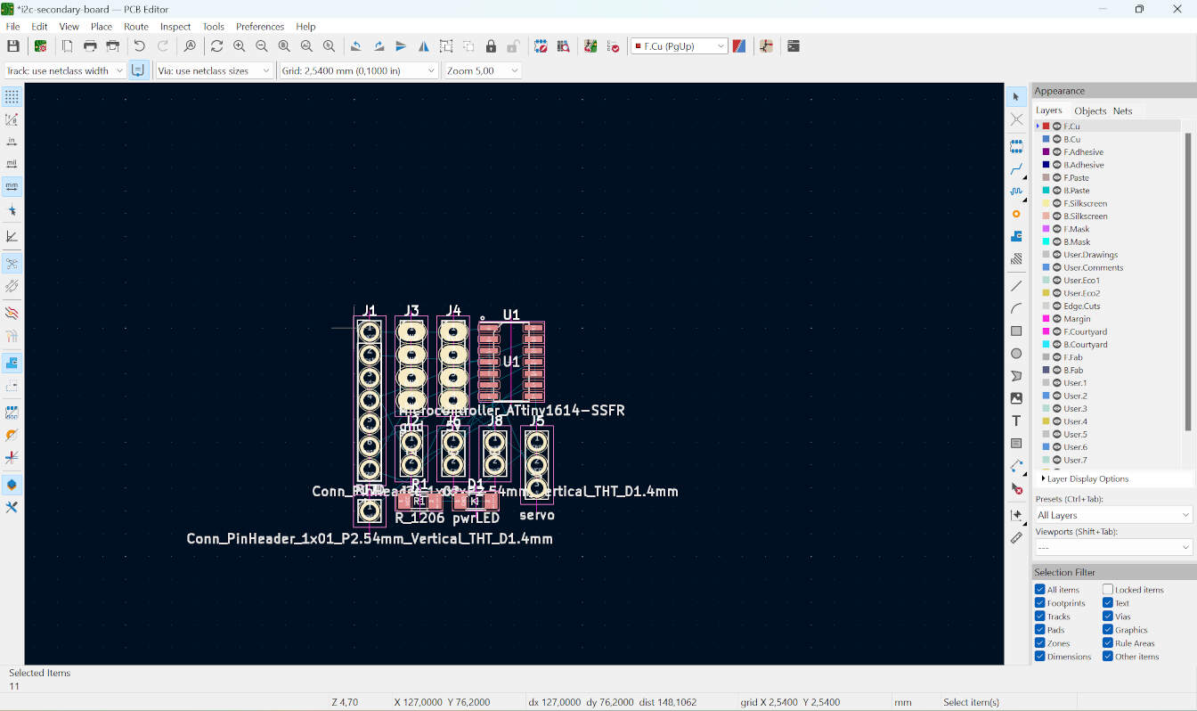
From there, I sketched how things would be placed and the overall look of the board. This helped me realize how certain parts would be wired. Later, I realized that there was a problem with the grounds. There were a few islands. At first, I thought of using a zero-ohm resistor to go over a line, but then I realized that I could make the underside of the board also a ground layer, and then I could just add rivets to connect all of the grounds.
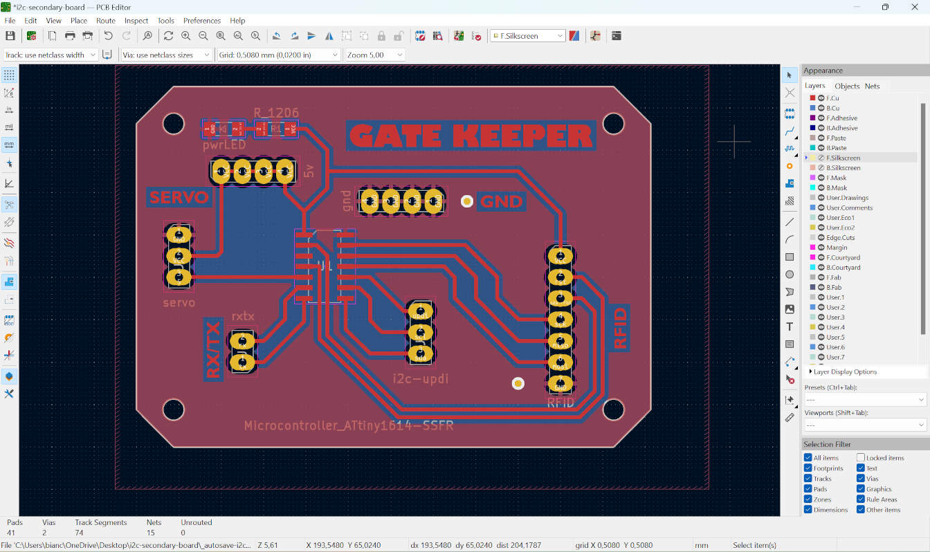
I´m much more familiar with the kikad now, so the design part went by quickly without any significant problems. for a better explanation on how i use kikad, check my week 04 and week 08 assignments.
For some reason, the milling process was a bit more complicated than usual. The first board I milled was beautiful except for the fact that the isolation between the lines was not completely milled through, so there was still a copper layer connecting everything. The next test I tried had a problem before the top layer was milled. This problem occurred during the autofocus part of the process, where the machine makes a small line somewhere on the copper and then, with a specialized camera, it locates this line and auto adjusts the height of the milling bit. The problem was that the line was not being made, so the machine was not able to locate it, putting the milling process on pause.

At this point, my instructor came to help me, and after many tries, we were yet to be able to make the line and have the machine autofocus. This made us suspect there was a problem with the tool bit, so we removed it and put it under a microscope with a newer bit to compare, and lo and behold, the bit was broken. We replaced it with the newer bit and were able to make the autofocus. However, yet again, the board came out beautiful except for the fact that the isolation was not milled through. After this, we tried a few more things, but eventually, even the software was not loading properly, so we decided to call it a day and look at this with fresh eyes the next day.

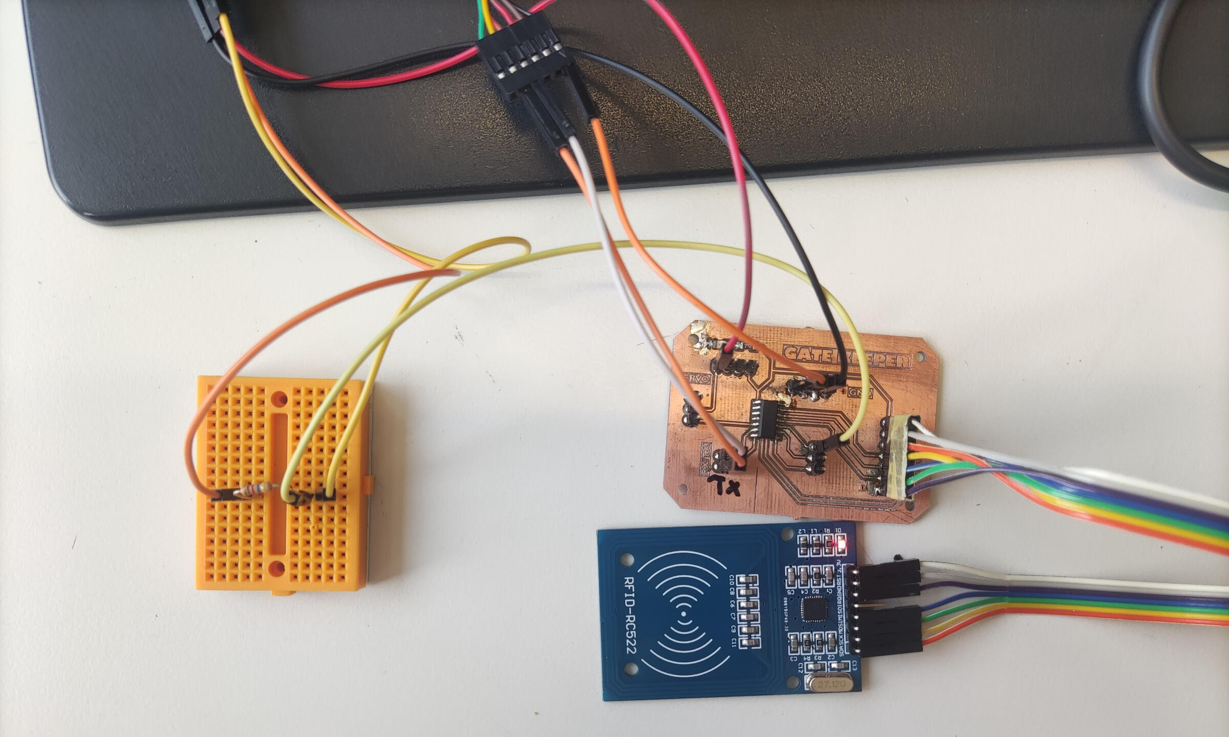
On the next day, I tried again, and eventually, I was able to mill the board. Then, I soldered the components onto the board. The next challenge was to program it. Since I don't have a programmer for this board, I instead used an FTDI cable, a breadboard, and a resistor to program it.
This works by connecting the GND and VCC of the board to the cable, while the UPDI pin is connected to the RX of the cable, and the resistor is connected to the TX of the cable. I had quite a bit of trouble with the next part, which was to program the board, as the ATtiny16 is not supported by the Arduino IDE. However, Spence Conde developed a board package called the megaTinyCore, which allows you to effortlessly program the latest series of ATtiny MCUs via the Arduino IDE. This whole process has to be done on an older version of the Arduino IDE because the board package has not been updated to the latest version of the Arduino IDE.

But... there was a problem with setting this up on my computer, I'm still not sure of the reason. So, I decided to try this on VS Code. To program C++ on VS Code, you need to install the PlatformIO extension. However, I still had problems connecting to my board :(
I was able to temporarily solve this problem by using the Arduino IDE on another computer at the lab to upload the code to the board. After sending a test code to the board, I went ahead and connected the RFID reader to it and sent another test code to see if the RFID reader was working with this board.
To see the serial monitor and receive the data from the RFID reader, I unplugged the wire from the UPDI pin and instead connected the RX of the board to the TX of the cable and the TX to RX. This worked great until I accidentally fried the board. I'm not completely sure how I did this, but I suspect it was when I connected the servo without unplugging the board from the computer :/// HOWEVER! I see this as an opportunity to improve the board design, and I'm already working on a new version of it.
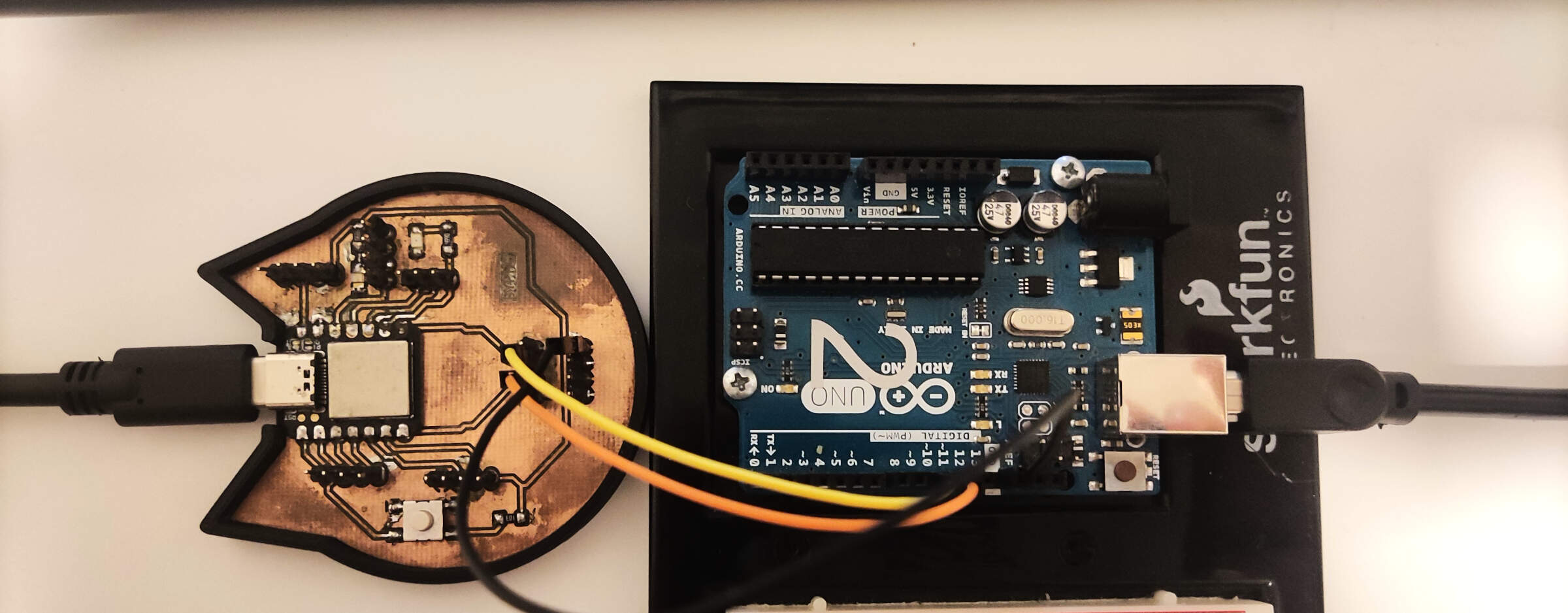
Here I tried some serial communication between two boards. I used the CAT PCB with the Xiao microcontroller from electronics-production week and an Arduino Uno (I used this instead of the board I made from electronics design week because I only have one USB-C cable right now :/ and I need access to two different ports). The wiring is simple, connect the RX from one board to the TX and vice versa, additionally connect the GND of the two boards, then connect the boards to different ports on your computer or another separate computer, to be able to see the different serial monitors for the different boards.
I wanted to test out the chat possibilities between two boards, and I found a simple code with a clear tutorial on how to do it (using Arduino IDE), this website. With this, I changed a few things to make it work with the Xiao microcontroller, and it worked great!
            #include <SoftwareSerial.h>

            SoftwareSerial chat(10, 11); // RX, TX

            int text;

            void setup()
            {
                // open hardware serial, TX = 1, RX = 0
                Serial.begin(9600);
                Serial.println("existentialist chat compiling...");
                Serial.println("loading...");
                // set the data rate for the SoftwareSerial port
                chat.begin(9600);
                delay(1000); // delay 1s to stabilize serial ports
                chat.println("what are your first words?");
            }

            void loop()
            {
                if (chat.available())
                    Serial.write(chat.read());

                if (Serial.available())
                {
                    Serial.print("me:   ");
                    while (Serial.available())
                    {
                        text = Serial.read();
                        chat.write(text);
                        Serial.write(text);
                    }
                    chat.println();
                    Serial.println();
                }
            }
            #include <SoftwareSerial.h>

            SoftwareSerial chat(7, 6);

            int text;
            void setup()
            {
                Serial.begin(9600);
                Serial.println("You are now awake...");
                chat.begin(9600);
                delay(1000);
                chat.println("what are your first words?");
            }

            void loop()
            {
                if (chat.available())
                    Serial.write(chat.read());

                if (Serial.available())
                {
                    Serial.print("me:   ");
                    while (Serial.available())
                    {
                        text = Serial.read();
                        chat.write(text);
                        Serial.write(text);
                    }
                    chat.println();
                    Serial.println();
                }
            }
The code for the two boards is basically the same, but it's important to change the pins for the software serial communication.
This is the song I used in the video, and in case you couldnt read what was on the serial monitor here it is:
In summary, this code sets up a software serial communication channel (chat) alongside the hardware serial communication. It allows bidirectional communication between the Arduino uno and the cat board using their respective RX and TX pins. The chat object receives data from the external device and echoes it back, while the Arduino can also send data to the external device via the hardware serial port.
Since I may or may not have fried the ATtiny for the gatekeeper PCB, and the replacement one is still being redesigned, for the I2C communication, I used the Arduino Uno board, the Cat PCB, and the PCB from Electronics Design Week that I like to call the brain. The wiring for the I2C circuit is very simple since I only need two wires from each board, plus the GND and 5V.

Regarding the code, I wanted to simulate/build a skeleton program for my final project. To do this, I already have in mind what I want the final code to do. The gatekeeper boards will be secondary and basically act as a middleman between the RFID and the brain board. This board will read my cat's RFID tags and send the information to the main board. The main board will then check if the tag is registered for this specific gate. If it is, it will send a signal to the gatekeeper board to move the servo and unlock the door. The reason I want to use I2C is to facilitate the modularity of my whole project. If all of the tag information is stored in the main board, it's easier to change the tags and add new ones. Otherwise, I would have to hard code the correct tag's UID into each gatekeeper board. Imagine if a cat lost their collar with the tag, it would be a pain to have to open up the cat house, remove the PCB, and change the code. With this setup, I would only need to change the tag information in the main board. I could also add an option in the web interface to add new tags.
With all of this said, for this week, what I'm doing is really simple, I built this off the hello.I2C.ino by Neil Gershenfeld, and changed it so that the main board would print the secondaery boards adress and also a letter or number that the secondary board sent. the secondary boarrd code is pretty simple, in the code i can set it´s adress as anything and also there is a line that sends a number or letter to the main board. This number will then be sent to the primary board, which will just print which board sent the number and the number itself.
            // Primary board code, or as I call it, the brain code.
		This program is the first step in my plan to use I2C in my final project.
		Here, I plan to simulate how the gatekeeper board will work with the main board.
		The brain board will receive information from the gatekeepers and print it in the serial monitor.
		This is a very basic and skeletal representation of how the final code will look.

             #include <Wire.h>

            void setup() {
               Serial.begin(115200);
               Wire.begin();
            }

            uint8_t address, count;

            void loop() {
               count = 0;
               Serial.println("start scan ...");
               for (address = 1; address < 127; address++) {
                  Wire.beginTransmission(address);
                  if (Wire.endTransmission() == 0) {
                     count += 1;
                     Serial.print("   found ");
                     Serial.print(address, DEC);
                     Serial.print(" (0x");
                     Serial.print(address, HEX);
                     Serial.println(")");


                     Wire.requestFrom(address, 1);
                     while (Wire.available()) {
                        char receivedChar = Wire.read();
                        Serial.print("   Received data: ");
                        Serial.println(receivedChar);
                     }
                  }
               }
               if (count == 0)
                  Serial.println("   no devices found");
               delay(1000);
            }
		// This is the code for the Gatekeeper PCBs.
		I plan on creating "dumb boards" for each cat house and connecting them to the Brain
		board via I2C.
		In the future, the dummy boards will only receive data from the RFID reader and then send
		it to the Brain board.
		The Brain board will then receive a command from this board to determine whether the servo
		should unlock the cat door.
		For now, this code is very simple and only receives a number from the serial monitor and sends
		it to the main board.

		#include <Wire.h>

		void setup() {
		   Wire.begin(2);
		   Wire.onRequest(requestEvent);
		}

		void loop() {

		   delay(1000);
		}

		void requestEvent() {

		   Wire.write("B");
		}
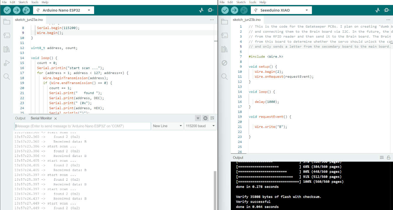
The code and serial monitor for the brain board is on the left, and on the right is the code for the gatekeeper board. "Received data: B" is what the brain board printed, along with the address of the gatekeeper board. Meanwhile, on the gatekeeper board, the code is simple. It just sends a "B" to the brain board.
for adding more boards, you have to change the board's address. I set the main board as 1, and the gatekeepers' addresses just go from there. So, in the code I provided, the address is 2 for the second board. For the third board, it uses the same code as the second one but with a different address.