Computer-Controlled Cutting
Group assignment
Here a link to the group assignment page, where my group and I documented the characterization of our laser
Individual Assignments:
Designing
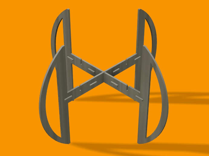
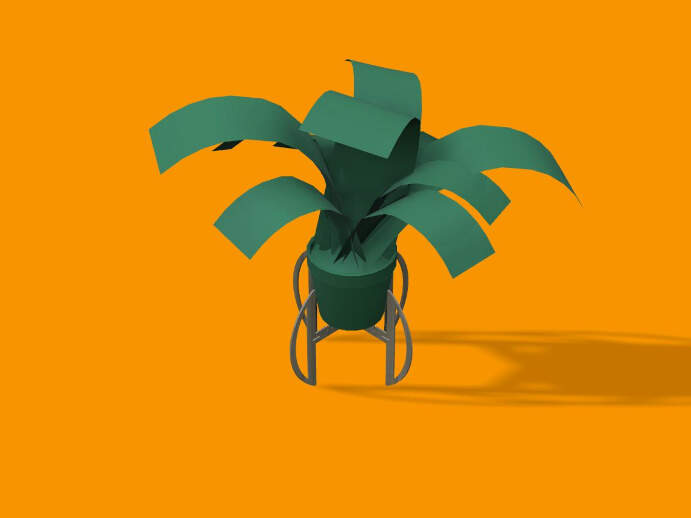
For this week, I decided to create a parametric construction kit for a plant stand that could be assembled in multiple ways. To do this, I used Fusion 360, a software I had already used in the previous assignments.
As I had already used Fusion, I was able to complete this assignment without any major issues. However, I did encounter some minor issues, such as the software crashing a few times, but I was able to resolve them quickly. Overall, I found this assignment to be quite enjoyable, as I was able to create a design that was both functional and aesthetically pleasing.
The design:
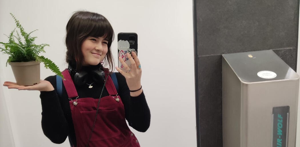
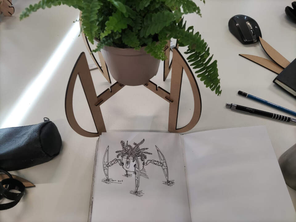
To start off i sketched on paper some ideas and planned out how it world work, I wanted it to look a bit minimalistic but also modern, i was also partialy inspierde by a doodle of a robot i had done the other day while looking at my fern.
once I had established the look and the main parts of the kit, I started sketching them in fusion 360.
In this week's lecture with Niel, he explained the use of parametric design, especially in laser cutting, for cutting joints. After watching a few tutorials on parametric design in Fusion360, I went ahead with it.
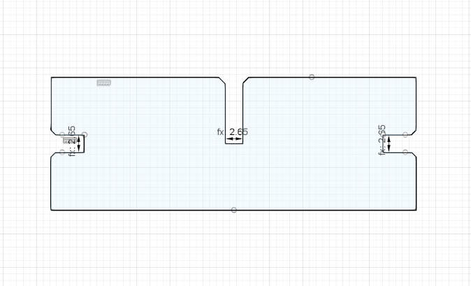
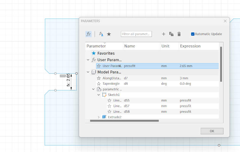
By using the keyboard shortcut "S" for search, I searched for "change parameters". I created a new 'user parameter' for the size of the press fit. After that, to add these parameters to my sketch, I used the dimension tool.
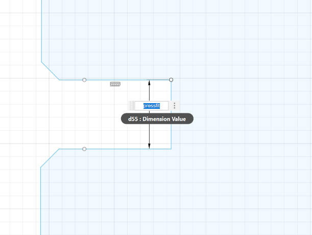
After that, I used the 'extrude' tool (keyboard shortcut E) to extrude the sketch and create the 3D model. I repeted the same process to design the other two parts, and in the end I was left with the 3 components for the plant stand.
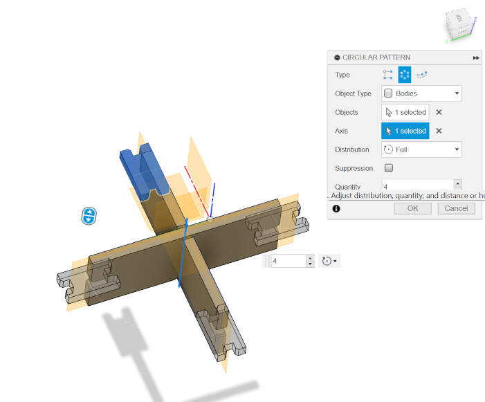
To put it all together I used the align tool, and also the circular pattern tool (see my documentation for this on the previous week)

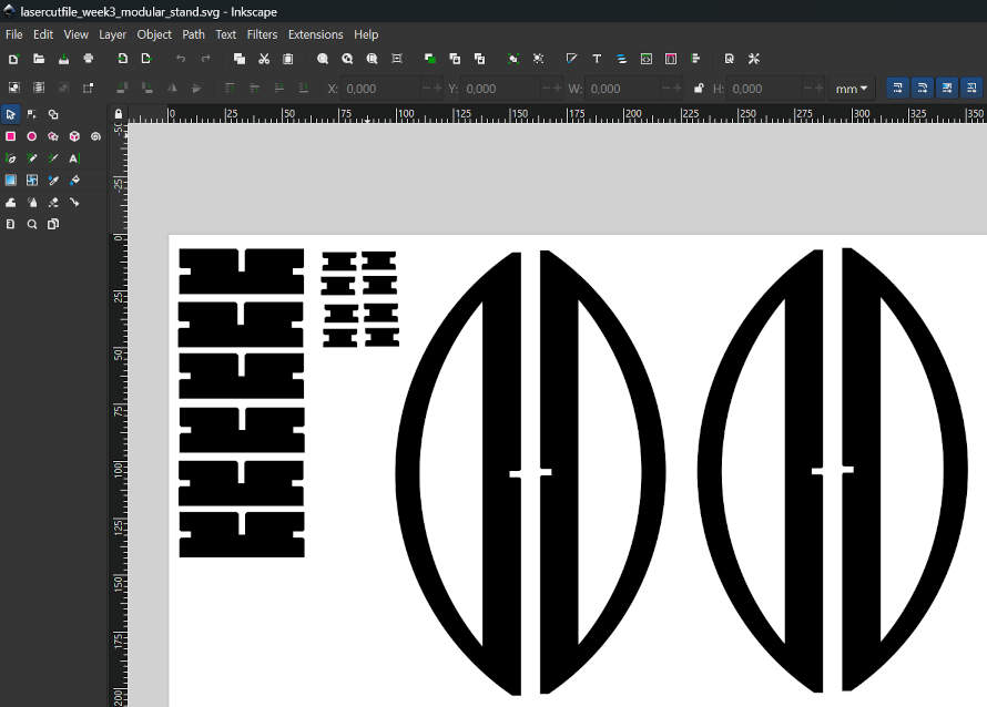
Next I used the fusion add on Shaper Utilities to save the faces of my design as svg files, which I then imported to inkscape to arrange for laser cutting.
Laser cutting
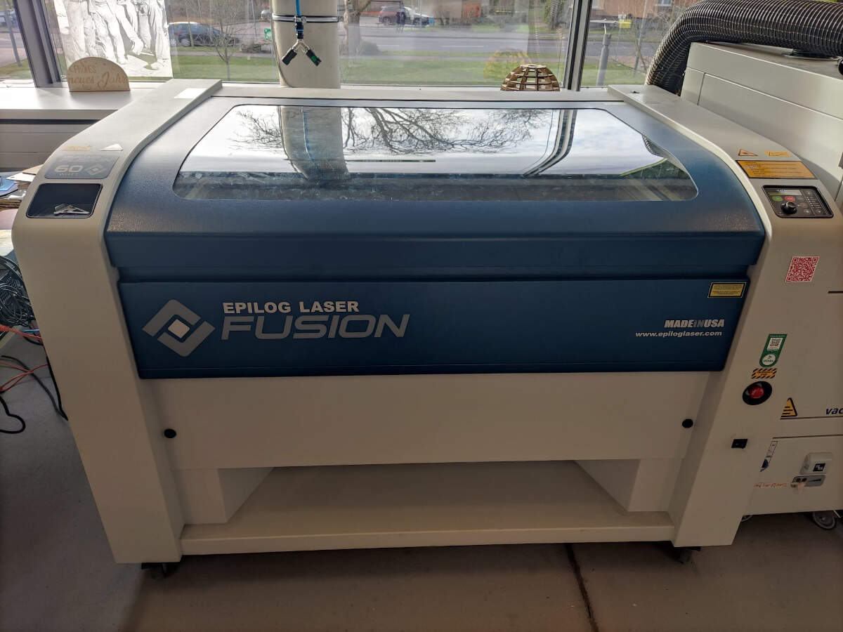
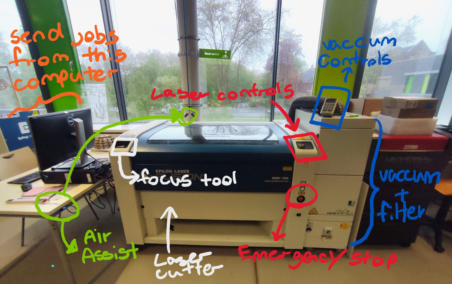
The laser cutter I used here at the lab is the Epilog Laser Fusion equipped with a 60 Watt CO2 laser, and the setup we have for it, is a smoke extractor and filter to the right, they are important because the laser cutter produces a lot of smoke and fumes and it is important to have a good ventilation system to avoid inhaling the fumes especialy when cutting materials like acrylic. The control panel, emergency stop button and the power switch are also located to the right of the machine. The valve for the air assist is located to the left. The air assist is connected to the laser head and it works to keep debris away, cool down the material being cut, and prevent the laser lens from getting dirty or cloudy. It is important to note that before operating and turning the laser on, the air assist and vacuum should be turned on first. These are important for the safety of the machine and the user.
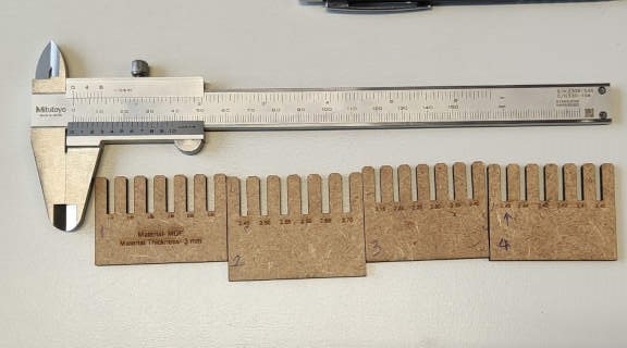
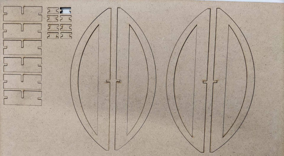
The material I settled on cutting is 3mm mdf, for the cut settings, in the group assignment we found that cutting with a speed of 5%, a power of 70% and a frequency of 30% were optimal for cutting this material.
To send the job to the laser cutter, I first need to open the the inkscape files on the computer connected to the laser, then I "print" the file and this sends the files to the software we use to control the laser.
On the software, I chose the cutting option as a “vector” for all of the parts. Since I want the laser to cut them out completely and not engrave them, I also made sure to set the speed, power, and frequency to the values we found to be optimal for cutting MDF. Lastly, in the software, I ensured that I placed them on the top-left corner and selected the laser cutter to cut the parts using the “Epilog Laser Fusion”. This step is necessary because we have another smaller laser cutter connected to this computer. After completing these steps, at the bottom of the screen in the laser cutter software, I click “print” to send the job to the laser.
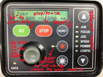
The last step is to ensure that the laser cutter is ready to cut. I made sure the air assist and vacuum were turned on. On the control panel of the machine, I set the focus. This is done by mounting the focus tool on the laser head and selecting the “focus” mode. Using the joystick, I controlled the Z-axis until I achieved the desired focus. Once this was set, I saved this height by pressing down on the joystick. It’s crucial to remember to remove the focus tool from the laser after this step.
Next, I set the zero position using the “jog” mode. Again, using the joystick, I adjusted the X and Y axes to establish the zero point. Once this was done, I could start the job by selecting “job”, checking if the job I sent from the computer was there, and then pressing “go”.
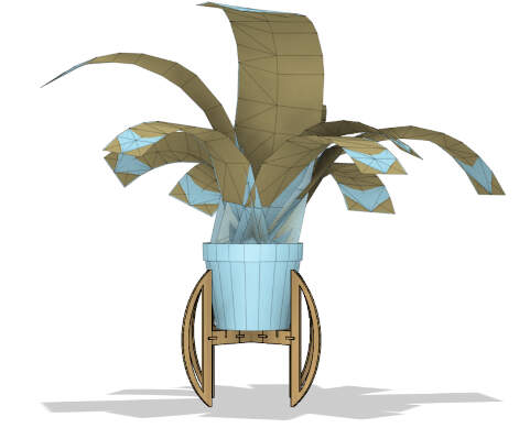
here´s a little stop motion video of the assembly^
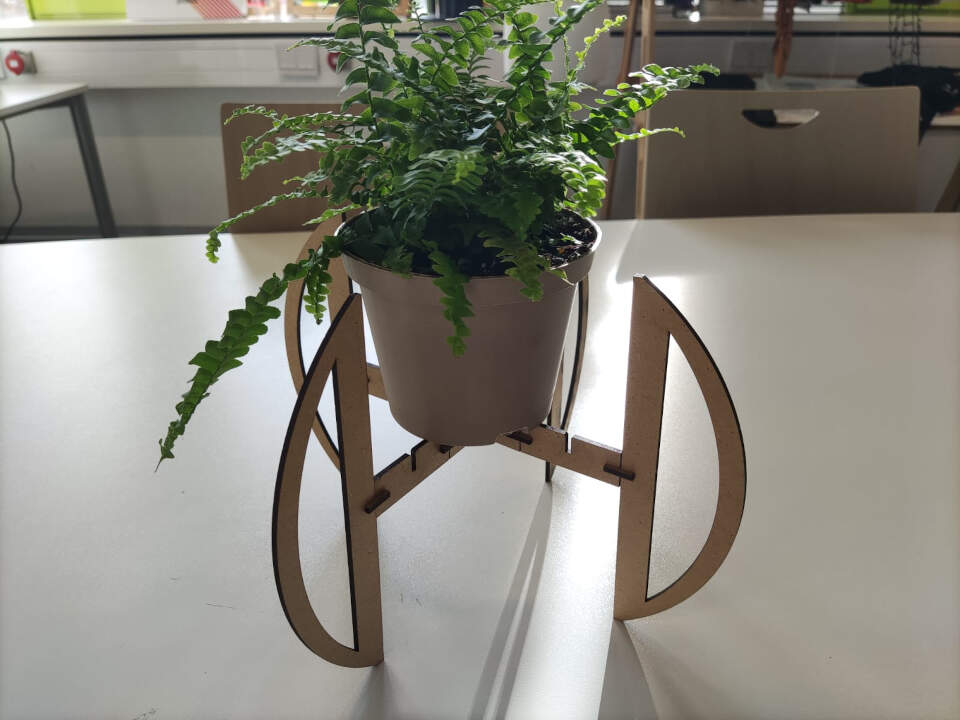
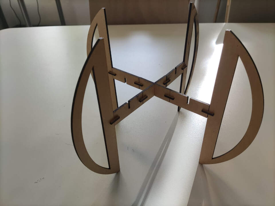
In the end it holds the plant´s weight and the joints fit perfectly! you know what they say "happy plant, happy life" ;)
Laser cutting flexible joints
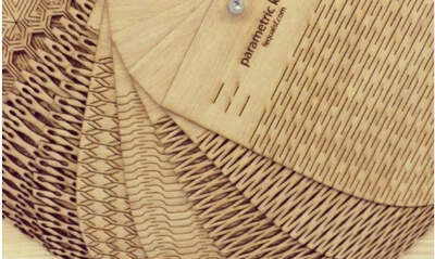
After searching the web, I found some cool ways people used flexture joints to make things like, lamp shade and book covervs, so I decided to try and make a little note book cover. this instructables page has some cool parametric templates and is what I used to make the cover
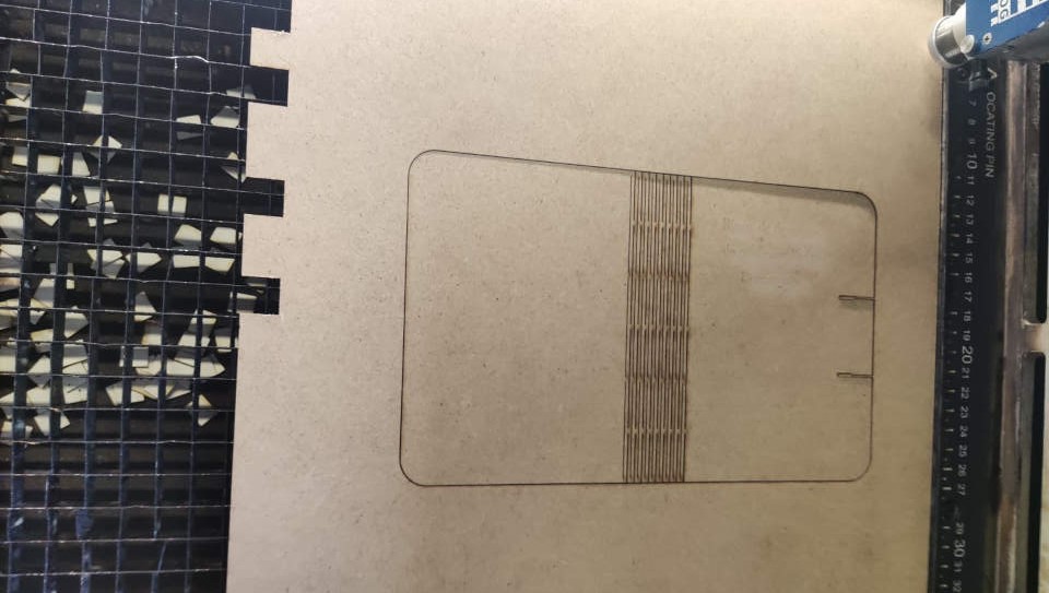
It bends!!
Vinyl Cutting
In Portugal at 'Algarve Fab Farm', I had the opportunity to work with a vinyl cutter, specifically the Silhouette Studio Cameo model. This tool became familiar to me as I enjoyed both collecting and creating stickers. I would often draw something and then use the vinyl cutter to bring my designs to life. so i was already familiar with this part of the assignment and was able to finish it quickly without much issues, mostly because i had already experienced the more annoying moments when the vinly cutter decides to be quriky
Desiging and software

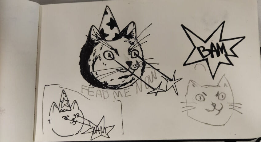
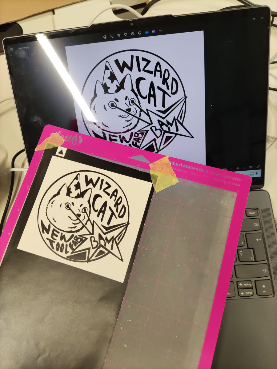
For this week, I found an old picture of my cat, Gary, which I had adorned with a wizard hat. and it inspiered me to create a laptop sticker featuring the image. To accomplish this, I opted to use Krita, the same software I used for previous assignments. My familiarity with Krita, along with it´s versatility, influenced my decision. Additionally, I recalled that in past experiences with the vinyl cutter, I had even designed stickers using a simple drawing app on my phone. Knowing this, I felt confident that the choice of software would not pose significant obstacles.
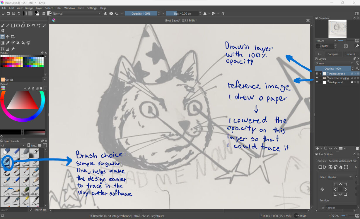
On Krita, I used the sketches I drew on paper to create a digital and more polished version. A tip for this part of the process is to not worry too much about the image format, as it doesn't really matter depending on the vinyl cutter software you use (I will talk more about this later).
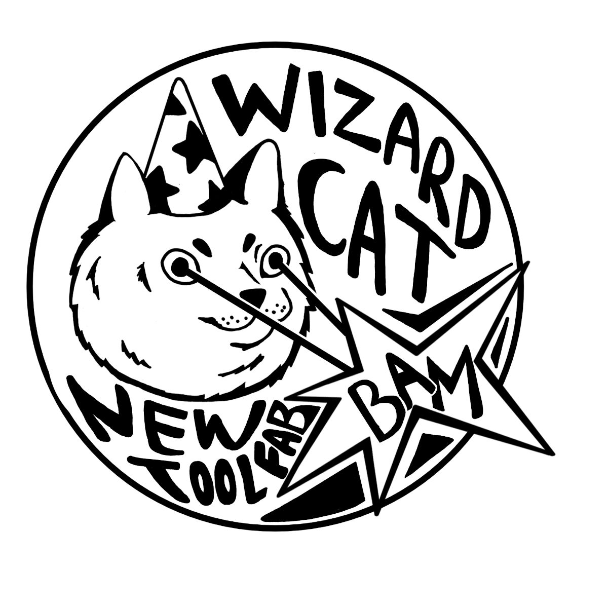
The vinyl cutter I used here at the lab is the Silhouette Studio Portrait 2, and I opted for sticker vinyl with a matte surface. I also used the Silhouette Studio software, where I was able to open my design and use the automatic tracing tool to get the outline of my design.
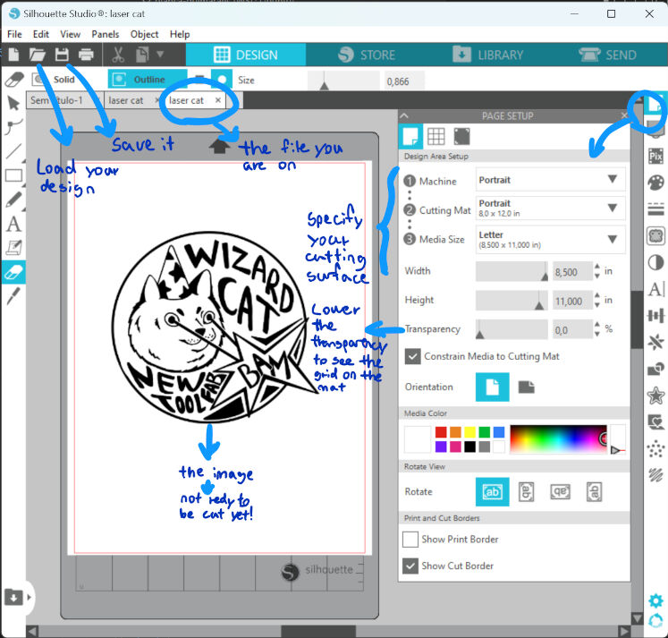
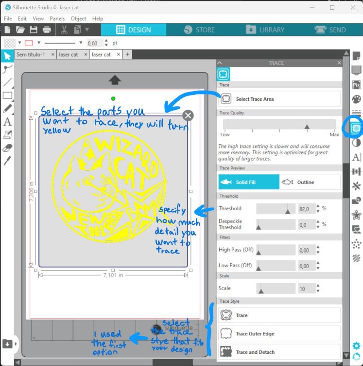
Returning to the point I made previously, here I show how I traced my design (I imported it as a jpg) and got the outline that the vinyl cutter will be able to cut, depending on the type of trace you use you will get different outcomes to cut
Cutting
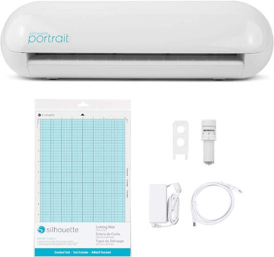
Here is a picture of the model of vinly cutter I am using^
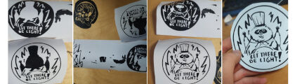
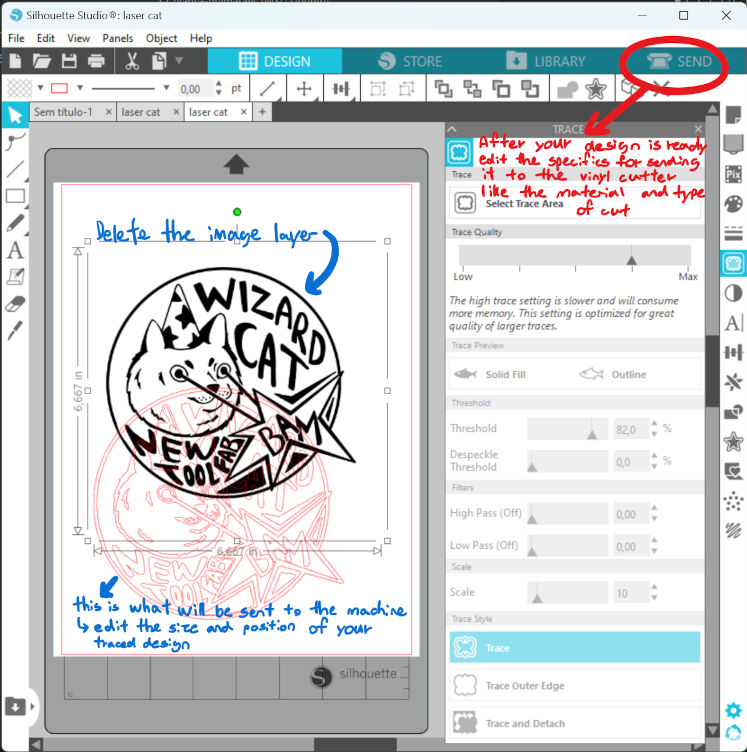
With my design prepared I clicked "send" to send the job to the machine and without any issue I got my sicker, one thing to note is that there were some flaws to my design, as the wisker dots on the cat were too small for the type of blade the vinly cutter used, so in the end they didn´t stay on the sticker.

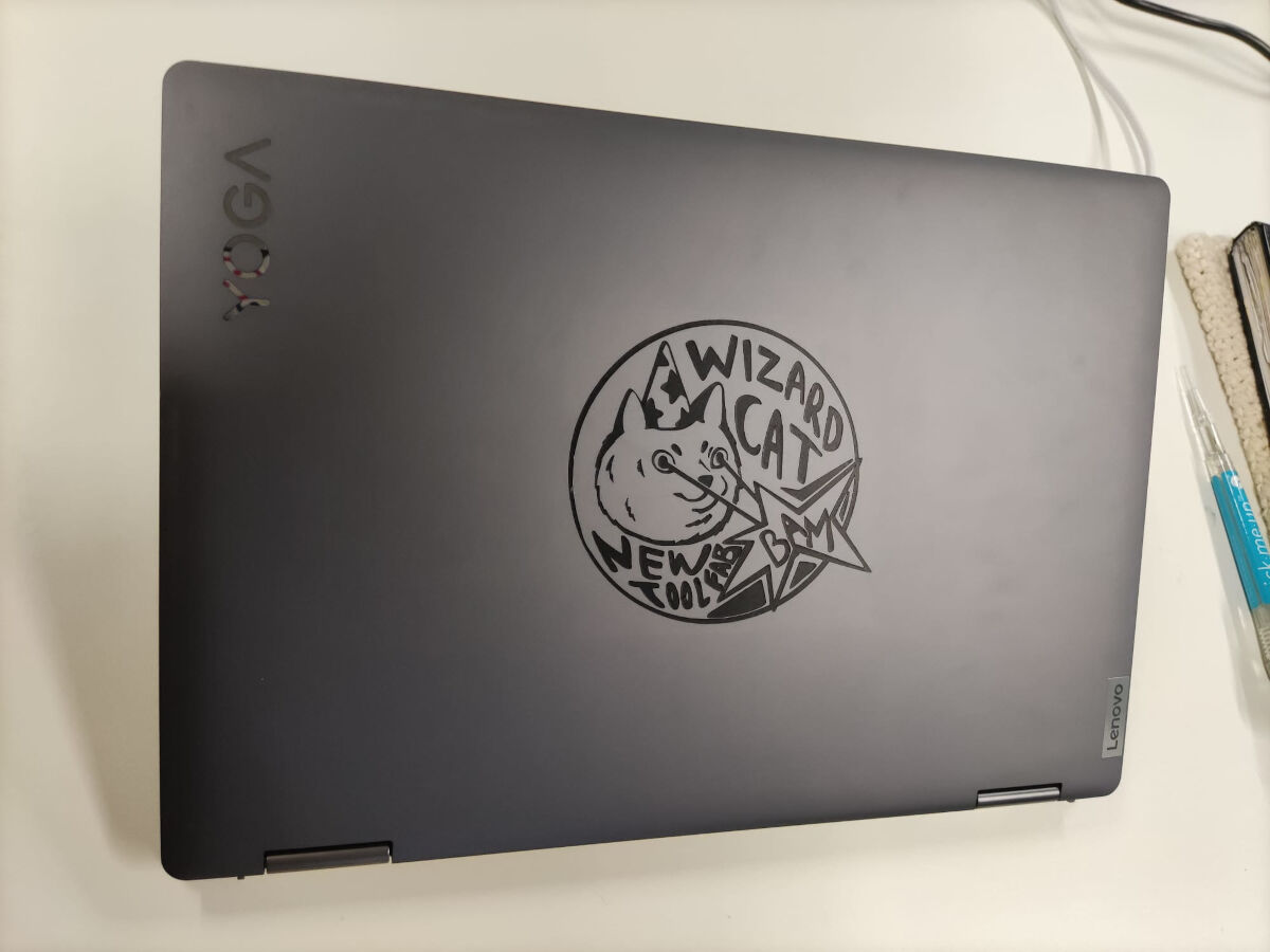
In the end I´m very happy with the end result!