Focus
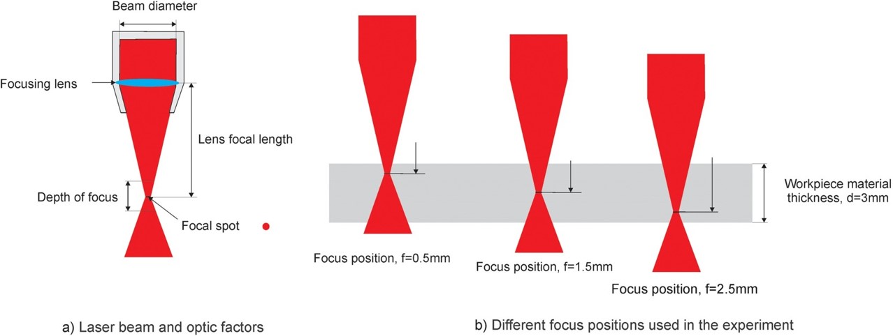
In laser cutting, focus refers to the concentration of the laser beam at a specific point, known as the focal point. Achieving the correct focus is important for the precision and quality of the cutting or engraving process. The focal point is where the laser beam attains its maximum power density, resulting in the highest temperature and energy concentration. This focused energy is what allows the laser to efficiently cut through or engrave materials.
The distance between the laser nozzle and the material's surface determines the focus. This distance is carefully calibrated to ensure that the laser beam converges to a sharp point. A well-defined focal point is essential for achieving fine details and preventing excessive heat dispersion that could affect the material.
Adjusting the focus becomes especially important when working with materials of varying thicknesses. Different materials may require slight alterations to the focal point.
Explanation of the focal point by Madić et al. 2021
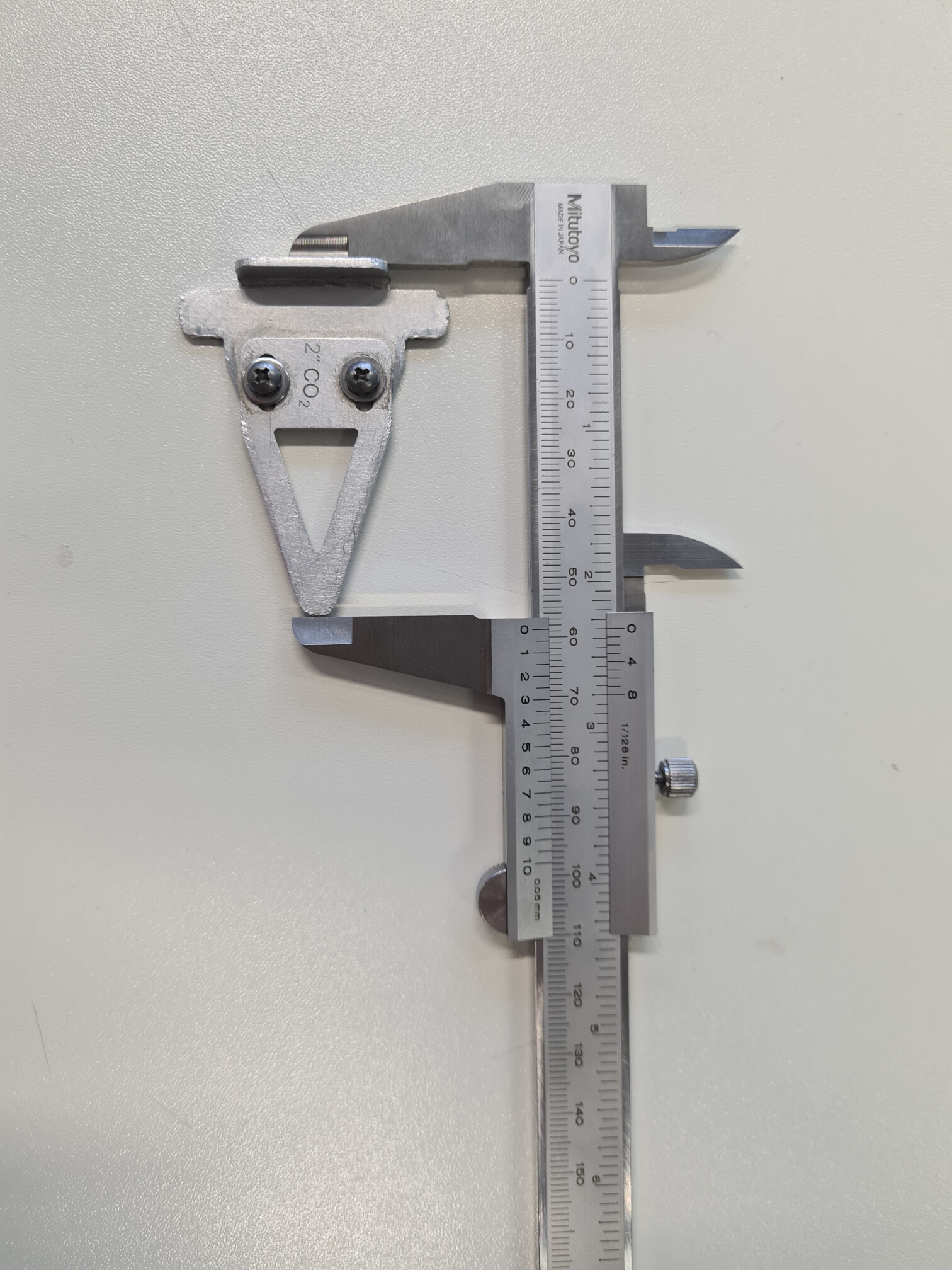
The first part of our group assignment was setting the focal point of the lasercutter right. For the lasercutter that we used, a small focussing tool is available that can be attached to the laser head. The z-axis of the machine then has to be moved such that the surface of the material on the bed touches the bottom of the tool slightly. By this, the laser should focus exactly on the top of the material. In case somebody uses thicker materials, it can be compensated by manually moving the z-axis by half of the thickness such that the focal point is in the middle of the material.
The last time, the focus of this lasercutter was calibrated and the tool adjusted accordingly, was probably some time ago. However, in order to calibrate it, we used the length of the tool which measured 58.75 mm in total as a rough estimate.
From this height as the origin, we moved the lasercutter's bed up and down and did some cuts. With this, it can then be assessed which height corresponds to a focal point on the top of the material by evaluating the thicknesses of the cuts. In case the cut is out of focus, the thickness is increased. Only if the focal point is exactly on top of the material, the cut will have a minium thickness.
For the first series of cuts, we started with a relatively rough range of movements, namely from -5 mm to +5 mm with 1 mm steps. For each of the eleven heights, we created a vertical path with a unique color in Rhino with a length of about 2.5 cm in a distance of 0.5 cm to each other.

From Rhino, this file was sent to the lasercutter via the network by using the printing dialog. In addition to choosing the right lasercutter as a "printer" there were two other settings that were important for this task: The scale had to be set to 1:1 and the colors had to be transmitted because after pressing "Print", the file opened in the lasercutter software where the vertical paths were identified as different objects due to their different colors. This allowed us to selectively turn the paths "On" and "Off" and by this only cut a selected path.
In preparation for the cuts, we used the focussing tool on a 3mm MDF board to find the zero position of the laser head. Then we started the series of cuts with the leftmost vertical path corresponding to a distance of +5 mm relative to the zero position. Firstly, we positioned the laser bed to -5.00 mm by moving the joystick down and pressing set. Then, in the lasercutter software we only turned the leftmost path on with a "vector" cut and a speed/power/frequency of 30/60/20 as the manual recommended for 3 mm thick wood. We then sent the lasercutting job to the lasercutter, where we then started the job by pressing "Go".
We repeated these steps for the remaining lines. Between each cut however, we decreased the distance of the laser head to the material by 1.00 mm and switched all paths to "Off" apart from the desired one. In the end, we obtained the following cuts:
-------------- Insert Image of cuttings from +5.00 to -5.00 mm (could not find this image)
From this photo, it is really easy to say, that a distance of -5 mm relative to the focussing tool length results in a really bad focus as the line is relatively thick and very much burnt. The cut is better for a height of +5 mm but the thinnest and cleanest lines are between a distance of +3 mm and +1 mm. Hence, we selected this range as a second series of cuts with steps of 0.25 mm between them.
For the second series, including nine cuts, we repeated the steps from above starting at a distance of +3.00 mm to +1.00 mm while moving the laser bed by -0.25 mm between different cuts. In total, we obtained the following cuts:

As you can see, this series of cuts was already a lot cleaner as the first series. The cut for a distance of +3.00 mm however was the worst. However, determining the best cut is relatively tricky as it is hard to see which one really is the thinnest line. Nevertheless, after a bit of discussion in our group, we selected the cuts of +1.50 mm, +1.75 mm and 2.00 mm as the bests. In the end, we increased the length of the focussing tool by 1.75 mm to ensure that the focal point is at the bottom end of the focussing tool and thus on the surface of the material.
Kerf
The kerf is the width of the laser. As this dimension is relatively small, measuring errors must be decreased by measuring a length consisting of multiple kerfs in a row. This can be done by cutting out multiple bars that are separated by a single path and thus a single laser width. We created this file by drawing a horizontal line with a width of 2.5 cm. It was duplicated 14 times, moved below it and distributed vertically with even vertical gaps. The ends were furthermore connected by a line, such that a rectangle with a height of about 10 cm consisting of 14 horizontal bars was created.

As the kerf varies for materials as different settings for speed/power/frequency are used. Therefore, we cut the paths from Inkscape on 4mm plywood, 3mm cardboard and 3mm MDF with the optimal settings that we characterized for each material in the previous section. As the laser traveled 15 times horizontally separating the bars, the height of the material cut away by 15 paths can be assessed by measuring (A) the inner height of the rectangle and (B) the height of all rectangles vertically pushed together. To obtain the kerf k, the difference between A and B must be divided by 15, i.e. kerf = (A - B)/15.

With this method, we obtained the kerf to be the following:
| Material | A [mm] | B [mm] | Kerf [mm] |
|---|---|---|---|
| Plywood 4 mm | 100.60 | 98.01 | 0.17 |
| Cardboard 3 mm | 101.8 | 96.7 | 0.34 |
| MDF 3 mm | 100.0 | 97.75 | 0.15 |
As shown, the kerf is relatively small for plywood and MDF which is a typical value. However, for cardboard, the kerf is relatively high. This might be caused as cardboard is material consisting of thin paper-like sheets. The lasercutter hence might easily burn away the sheets inducing a high kerf.
Materials
To determine the optimal laser cutting parameters for various materials, we employed a sample testing approach using an Inkscape files. The first featured a matrix design of rectangles using different colors to make the rectangles distinguishable for the epilog software and manually assign different power and speed settings while maintaining a constant frequency. The second file was used after determining the parameters, to determine the kerf for every material.
Overview of the Optimal Settings
The following table concludes the optimal settings for the materials with respect to speed, power and frequency of the laser.
| Material | Speed [%] | Power [%] | Frequency [%] |
|---|---|---|---|
| Plywood 4 mm | 17 | 90 | 20 |
| Cardboard 3 mm | 45 | 85 | 20 |
| MDF 3 mm | 5 | 70 | 30 |
MDF
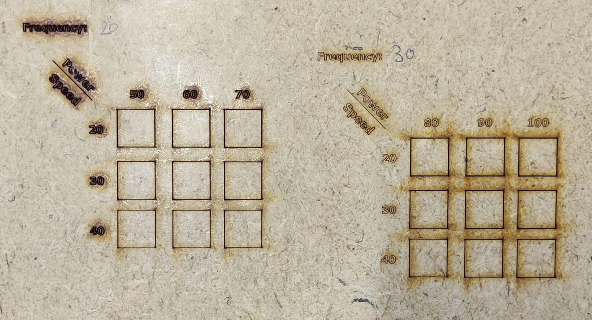
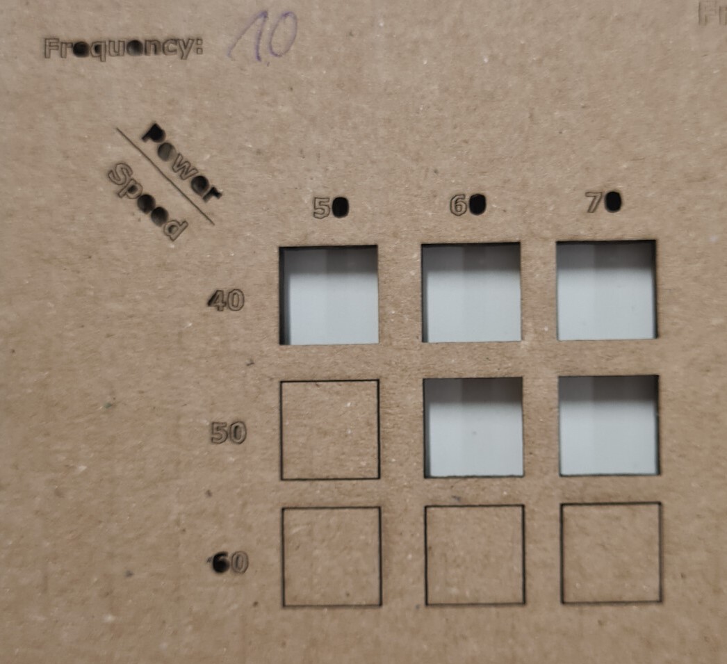
To assess the optimal speed, power and frequency, we started with an estimate for these parameters from the manual. As there was no MDF present in the table, we went with the values for wood with a thickness of 3 mm, namely 30, 60 and 20 for speed, power and frequency. Hence, for the sample test, we started with a frequency of 20 and values for the speed of 20, 30 and 40 and for the power of 50, 60 and 70.
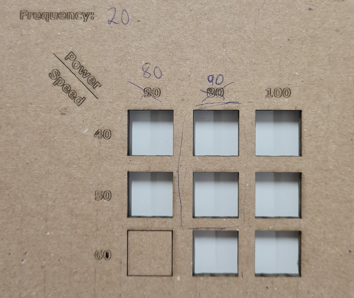
However, we noticed that none of the squares were actually cut. Therefore, we repeated the sample test fo the same speed with a slightly higher frequency of 30 and a power of 80, 90 and 100.
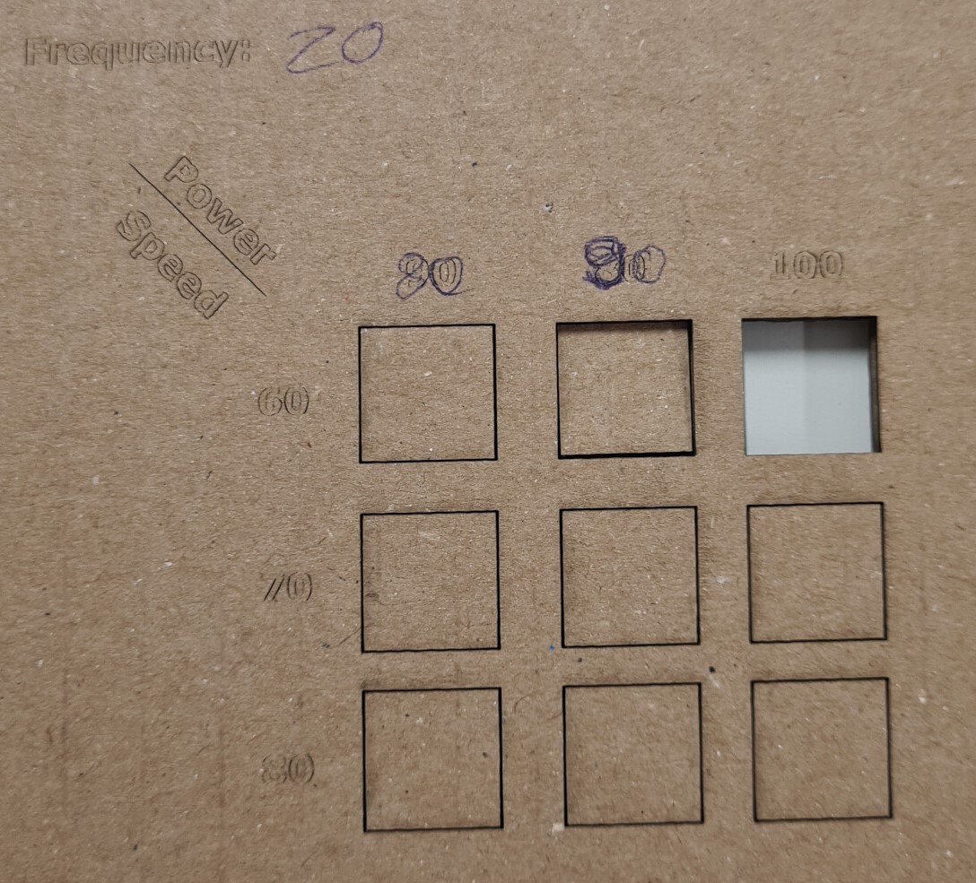
But... not even with these settings were were able to cut through. Hence, we decreased the speed to 5, 10 and 15 and tried different settings. In the end, did one test sample with a speed to 5, 10 and 15, power of 70, 80 and 90 and a frequency of 30.

And this gave us really good results. The cuts were relatively clean and not really burned. So in the end, we decided that a speed of 5, a power of 70 and a frequency of 30 were optimal.
Cardboard
We started with Cardboard (thickness: 3 mm) and used some settings we assumed would work to help us determine the right values for cutting: 40,50 and 10 for speed, power and frequency. so for the sample test, we started with a frequency of 10 and values for the speed of 40, 50 and 60 and for the power of 50, 60 and 70.
From this first test we learned that the cardboard was being cut with more power and slower speeds, but also burnt on its under side
In the second test, we maintained the same frequency of 10, but increased the power to 80, 90 and 100, and the speed to 60, 70 and 80. Here the only two parts that cut through we also observed burning on the underside.

For the third run, we decreased the speed, maintained the power, and increased the frequency to 20. The result was mostly clean cuts. But to be sure, we ran another test increasing the speed and maintaining the power and frequency. In this test, the results we got were that for the most part, the cardboard wasn't completely cut through.
By re-analyzing the third test, we found that the cleanest cuts were between speed=40, power=80 and speed=50, power=90. So we concluded that the optimal setting for cutting 3mm cardboard is speed=45, power=85, and frequency=20.
Plywood:
We started with plywood (thickness: 4 mm) and used the settings recommended by the epilog manual as guideline for our cutting test.
In the first run with the shown settings, the laser cutter did not cut the plywood.


In the second run, we increased power and decreased speed. The plywood was almost cut through and we only needed little power to push one sample out of the plywood.
For the third run, we decreased the speed and increased the power. The result was a clean cut with a little bit of burn marks.

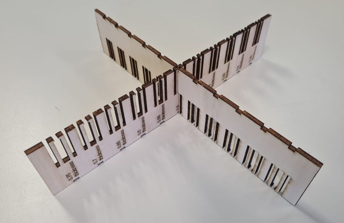
Joint clearance: Press Fit, Chamfer, and Finger Joints
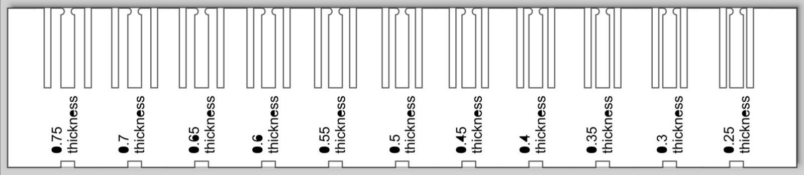
To achieve optimal fits for press fit, chamfer, and finger joints, it is crucial to determine the right clearances. This can be facilitated through the use of a parametric comb, featuring slots with varying widths based on the kerf of the laser cutter and the thickness of the material. We applied this approach to MDF sheets with thicknesses of 1.5 mm (using a 0.15 mm kerf) and 4 mm (with a 0.17 mm kerf).
- Input the parameters in Fusion 360
- Right-click on the sketch and select "Save as DXF"
- Open the DXF file in Inkscape and organize operations by assigning consistent colors to group different elements
- Remove projection lines
- Send the file to the laser cutter software
When working with plywood, we found that a fit of Thickness + 0.5 Kerf provided the best results. Alternatively, for a slightly looser fit that facilitates easier disassembly, Thickness + 0.25 Kerf proved to be a suitable option. By following this methodical process, we ensured precision and adaptability in our joints, leading to successful outcomes in both MDF and plywood applications for our individual projects.


Press Fit With Chamfer Joint for MDF
As a first test, we started with the width of the 3mm MDF and reduced it by 0.5mm 24 times. We found that some were too tight and others were too loose. With these tests, we narrowed down to a clearance between 2.59mm (which was a bit too tight) and 2.71mm (which was just the tiniest bit loose). Further tests revealed that the optimal clearance was 2.65mm for 3mm of MDF.
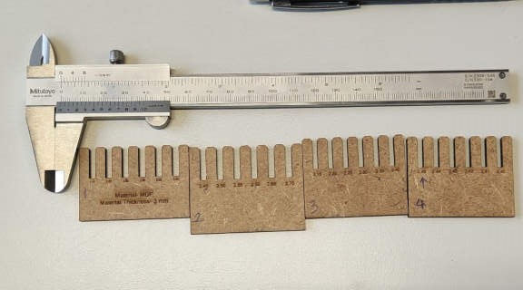
these were the faild first tests^ where none fit just right
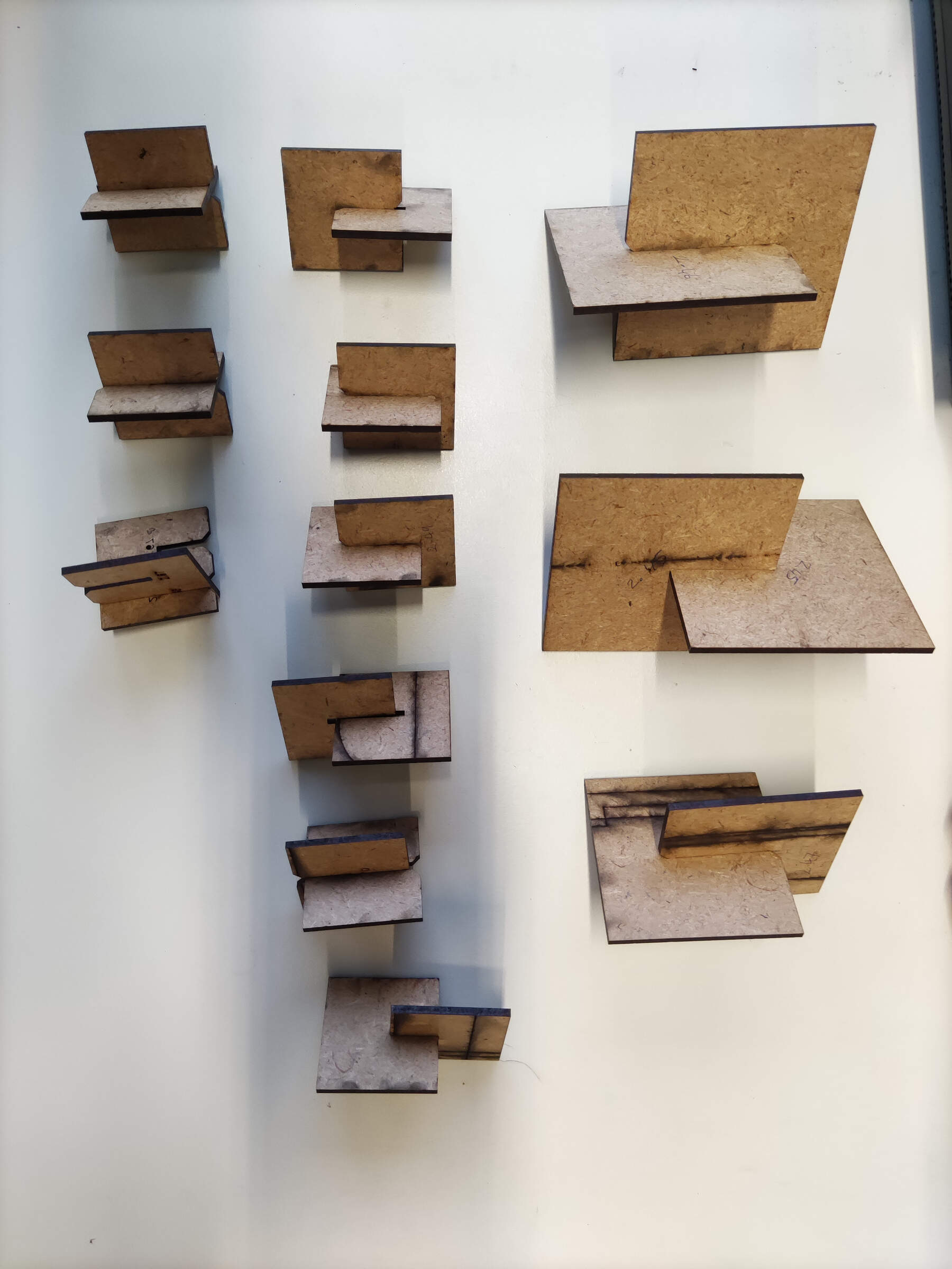
^second batch of tests where we went from 2.75 and kept decreasing
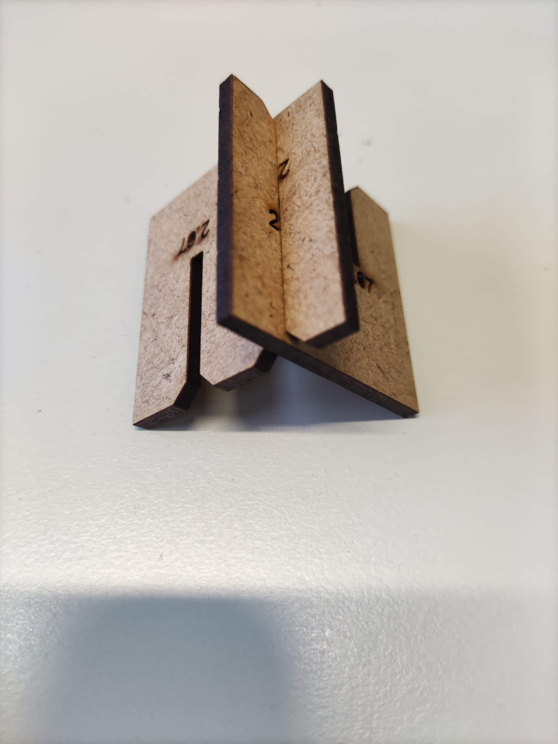
^Perfect fit! 2.65mm
Joint Type: Flexures
As a second type of joint, we picked the flexure fit, which consists of two flexible structures extending from the bulk material with a bulge on the end to secure it in place. As we did not know, what thickness the flexures had to be, we designed a comb with different thicknesses of the flexures in relation to the thickness of the material.
In Fusion 360, we designed the sketch for the comb parametrically accounting for kerf and the clearance. Specifically, the slots between the flexures had a height of the thickness plus 0.5 times the kerf of 0.17 mm, which we discovered to guarantee a good an tight fit for press fits. The flexures were between 1 mm and 3 mm wide which is equivalent to a width of 25% and 75% of the thickness of the material (4mm). From Fusion, the sketch was exported with the add-in "Shaper Original" as an .svg file.
We opened the .svg file on the computer connected to the lasercutter, where we selected a "vector" cut and set the speed, power and frequency to 17, 90 and 20. These are the optimal settings for the material we will be cutting, namely plywood with a thickness of 4 mm. The settings for the text were a speed, power and frequency of 100, 20 and 20 which should yield marking. With "Print", we send the job to the lasercutter.
Lastly, we set the focus of the lasercutter, moved the laser head to the right position and started the job. This resulted in these two pieces. Apart from the fact, that only one piece has text on it, they are identical.

Then we tested the flexure joint by joining the slots with the same flexure widths. Here, we found that widths of 1 mm are already very small such that the flexures are easily bent but also broken. For widths of about 3 mm, the flexures were too stiff and did not bend a lot. For thicknesses of about 2 mm, say from 45 % to 55% of the material's thickness, the flexures' behavior was realtively good. They were easy to bend but not too fragile.