Printed Circuit Boards
designing, producing, progrmming and burning boards...
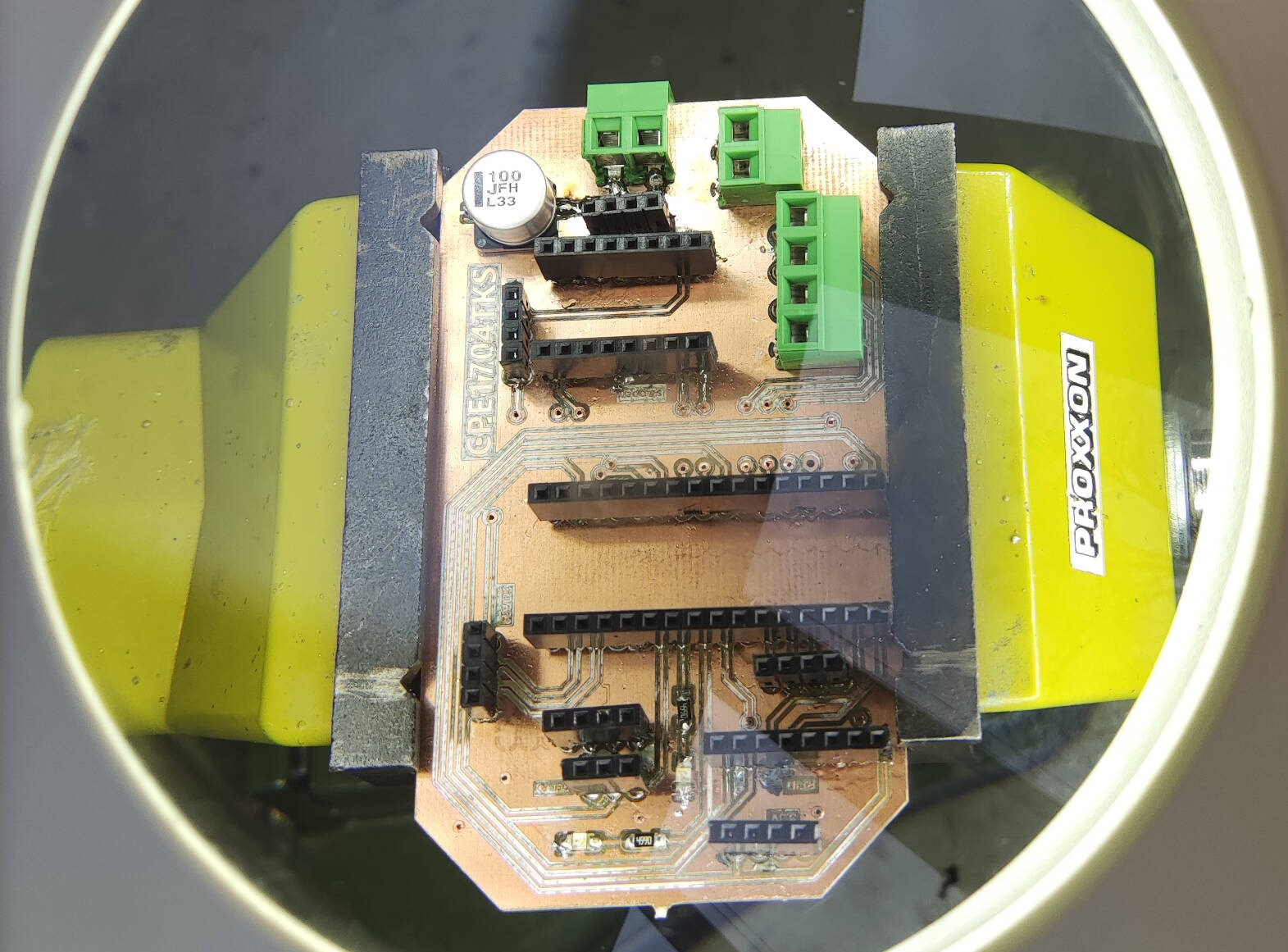
the final pcbs

Regarding the PCBs I made for my final project, I went through a few iterations, ideas, and microcontrollers. Initially during networking comunications week I designed and made a PCB that housed the Arduino Nano ESP32 as the microcontroller for the main board

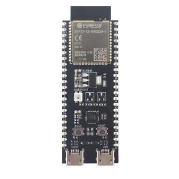
However, this board was not very reliable, and I ran into some issues with it regarding libraries and compatibility with setting up the programming environment in PlatformIO. This led me to look at other alternative boards that still allowed for Bluetooth and WiFi capabilities without having to add any additional modules. I settled on using an ESP32. At the lab, I tried to use some boards we already had, but they were not functioning properly, and I was unable to program them. This led me to search online, and I found a cheap ESP32S3 on Amazon. From there, I designed a board with this as the "brain" and produced it.
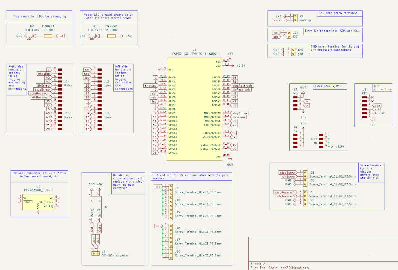
the main board
- esp32-s3 wroom 1
- two LEDs: power status and a programmable one
- 16 pin headers on each side of the board for easy connection and rewiireing incase of treck problems or the need for diferent pins to be used
- End stop screw terminal (gnd and digital pin)
- extra i2c connetion(sda and scl)
- uart connection (tx and rx)
- extra pins for gnd, 5v and 3.3v
- RTC connection pin header(sda,scl,gnd, 5v)
- screw terminals for the step and dir pins of the two stepper motors
- 9 screw terminals for SDA and SCL connections each, for i2c connections with the gate keeper boards
- dc buck converter for the power to the board and tthe rest of the project
refelcting on this board now, I realise many mistakes and improvements that could be made here, so i made a list of them:
- Microcontroller problems
- There is a problem with almost all ESP32 boards. This problem is that there are millions of different versions of the same board that use the same ESP32 module but are wired differently. Therefore, they have different pinouts, and it's tricky to find the correct one for the board you get. With the board I settled on, I only ran into this problem later on when I was already developing most of the code. The datasheet I got from Amazon was only for the module and not the board, so I had to look up this board. I found a pinout of the same board but made by a different company. At first, I thought there was no problem. However, I ran into many problems with the connections, and it got to the point where I had to test the actual connection between the module and the pins on the board. I found out that the pinout was different, and I had to change all the connections on the board and the code. But by this point, I had already made the board, and time was running out, so I had to make a lot of jumpers. This is to say that I'm already working on a much better board. However, the one I have, although it does not look the best, still works and does its job for now.
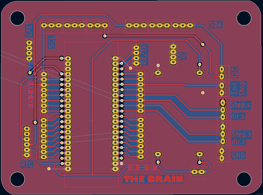
- PCB design problems
- There are a few problems with the PCB design. Firstly, the board is too big. I could have made it smaller, but at the time I had not truly noticed how big it was, and the inclusion of many screw terminals made it even bigger.
- Secondly, the board is not very well organized. I could have made it much better. For example, positioning the screw terminals in a more strategic way so that it would be easier to wire and rewire in a small space for the future.
- Thirdly, the board is not very well labeled. Although this problem stemmed from the fact that almost all of the connections had to be changed because of the pinout problem, I could have also put the label on the other side of the board, the side where the screw terminals are, so that I could read it easily when the board is in use.
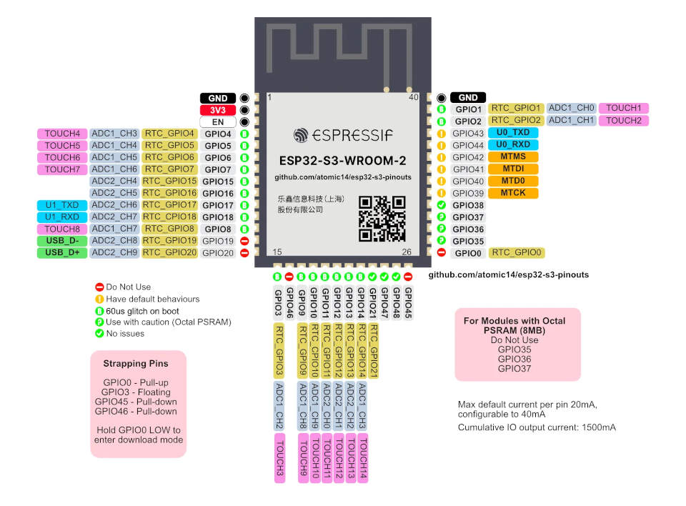
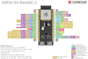
this is the pinout of the actuall module I used, I found this site that explains this better and informs which pins you should avoid and which ones are safe to use. here is the link to the site.
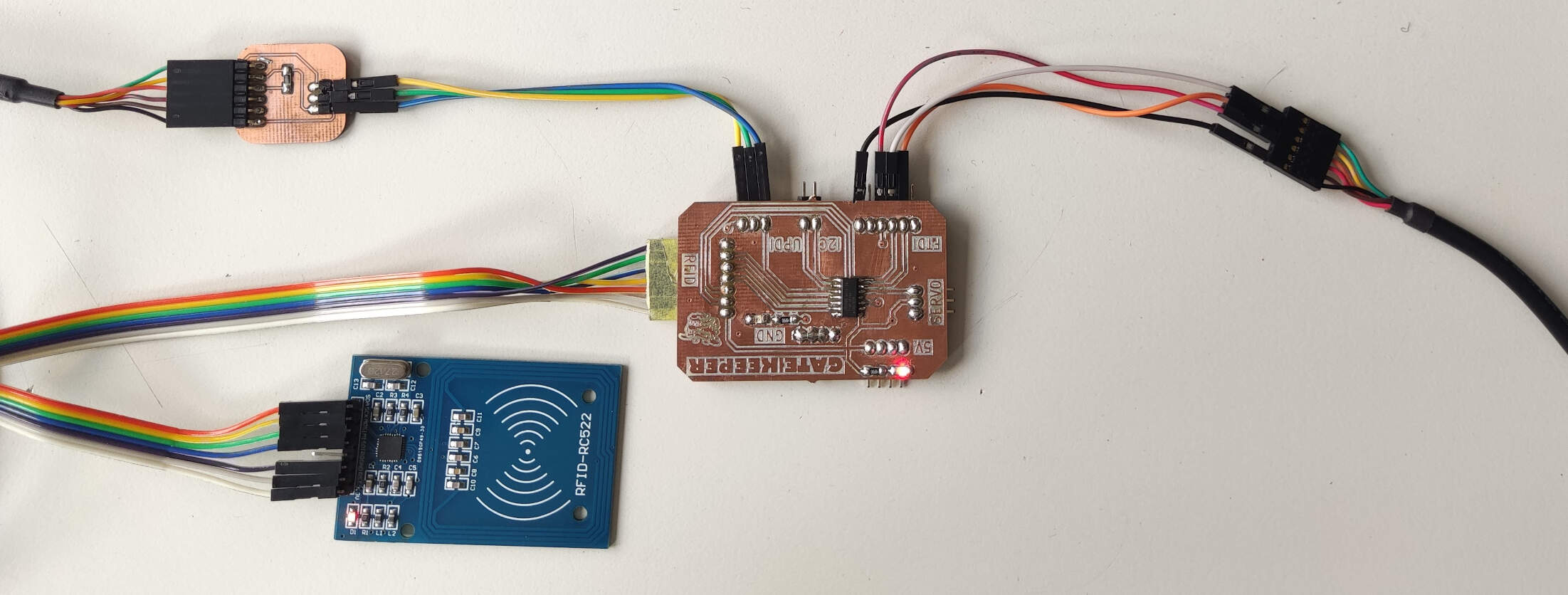
the gate keeper
Regarding the cat door mechanism and its PCB, I had already designed it during inputs week. I decided upon a "dummy board" system, meaning that each cat house/module would have its own small PCB, and these would connect to the main one via I2C or already contain the simple code for the RFID and servo. I called the dummy boards "the gate keeper" (as a reference to the Ghostbusters movie ;P).
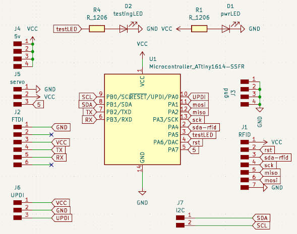
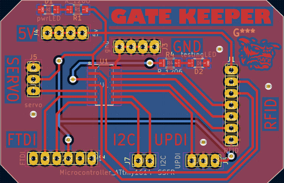
the gate keeper features:
- ATtiny1614
- RFID reader connection
- servo motor connection
- two LEDs: power status and a programmable one
- I2C connection for communication with the main board
- extra pins for gnd and 5V
- UPDI connection for programming and debugging
- FTDI connections for bridging the USB port to a UART peripheral interface(ex: acessing the serial monitor)
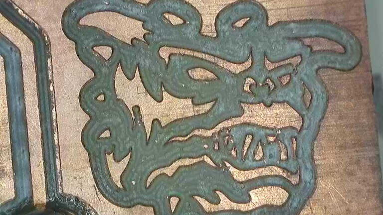
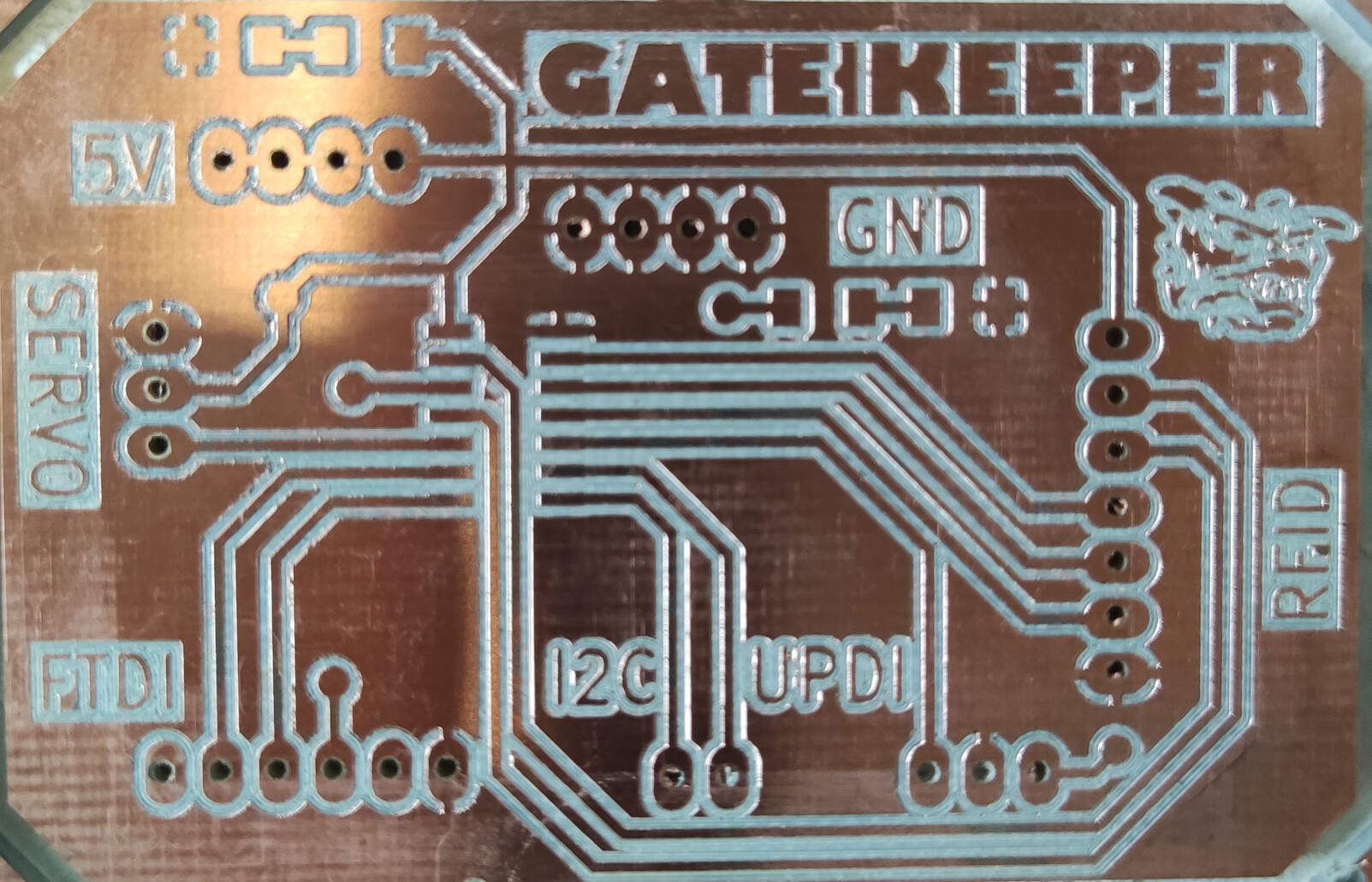
- I also added a little drawing on the board of the character "zuul" from the movie Ghostbusters, as a reference to the "gate keeper" name, it makes it look pretty cool and I wanted to see how much detail I could get on the board
To programm this board I also had to make a little adaptor to connect the the updi pins to a FTDI cable, so I could program it using the Arduino IDE. and to connect to the serial monitor i dont need to use the adaptor I can just connect the FTDI cable to the FTDI connection pins on the board. for this I followed Adrian Torres ATtiny docummentation.
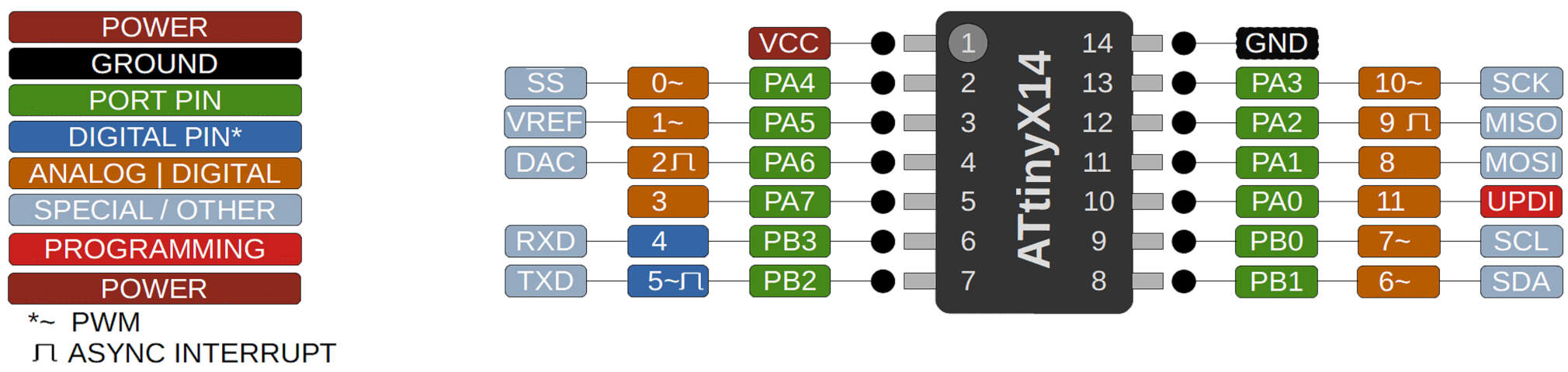
About the ATtiny 1614
The ATtiny1614 is a low-cost microcontroller featuring the 8-bit AVR® processor with hardware multiplier, running at up to 20 MHz and with 16 KB Flash, 2 KB SRAM and 128B of EEPROM in a 14-pin package.
this microcontroller is pretty good, however programming it was a bit of a challenge, since i made this board first, I was still programming with arduino IDE, and as I read on Adrian's documentation, I had to install the megaTinyCore to be able to program it. this however did not work on my computer, I tried many diferent ways but it didnt seem to work.
To summarize what needs to be done in order to program the ATtiny1614 in Arduino IDE (although it's best to check out the SpenceKonde/ATTinyCore GitHub page for the most recent information), here is a list of the steps I followed:
- First things first, unfortunately, the most recent versions of Arduino IDE do not work with the megaTinyCore, so you have to download an older version of the IDE. You can find the previous versions here.
- Then you have to install the megaTinyCore. The megaTinyCore, created by Spencer Konde, is an Arduino Core platform for tinyAVR 0, 1, and 2 Series MCUs that were released by Microchip between 2017 - 2021. The megaTinyCore allows users to use those Modern AVR chips like an Arduino under the Arduino IDE. In my opinion, it's pretty great. What isn't great is that it hasn't been updated in a while, thus the problems with the most recent versions of the IDE and why you need to download an older version. The core installation, as instructed on the installation page, is pretty simple. You can either install it through the boards manager or manually. Because I ran into some trouble, I actually tried both methods. However, the one I recommend is through the boards manager. It's much easier, and you don't have to worry about the files being in the right place, which gets a bit difficult when you have two different versions of Arduino downloaded on your computer. The boards manager URL is: http://drazzy.com/package_drazzy.com_index.json.
- Go to "File" -> "Preferences" -> enter the above URL in "Additional Boards Manager URLs".
- Then go to "Tools" -> "Boards" -> "Boards Manager...".
- Next, you need to select "ATTinyCore by Spence Konde" and click "Install". That should now allow you to choose which ATtiny board you want to use.
- From here it's business as usual and you can now select which boards you have and all of that and start programming it. The problem I later realized I was having with my computer is that I had initially downloaded an older version that I thought still worked with the megaTinyCore. However, this did not work. Later, during open time on a Saturday, I explained my problem to Adrian Torres, who suggested that I try downloading version 1.8.13, and that worked.
The programm I uploaded to this board was the same one I used for the input devices week assignment,