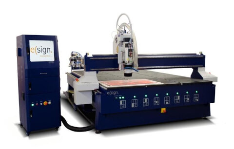
ABOUT OUR MACHINE
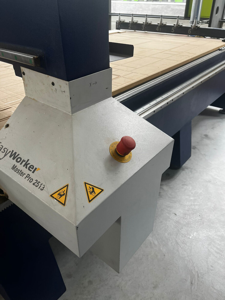
The big CNC in our lab is the "eLsign EasyWorker
MasterPro 2513".
The technical data for the CNC is as follows:
- The machine has a working area of 2500mm x 1300mm x 200mm.
- The machine operates at a speed of up to 19,000mm/min, ensuring swift movement and
processing.
- Precision linear guidance is utilized for accurate and smooth guidance.
- In terms of data formats, the machinery is compatible with G-Code and HPGL.
- Last but not least, the power supply requirements are versatile, accommodating either 3
Phases or 1 Phase with a voltage of 400V or 230V.
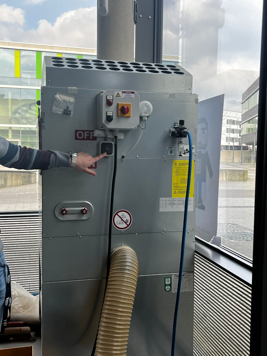
Additional modifications:
- an extension to the vacuum/ dust collection system plus the structure mounted to hold up
the tube, plus the actual vacuum
- Automatic tool exchange
CAM with Fusion 360
In our CAM processes, we employed Fusion 360. To thoroughly assess runout, alignment, fixturing,
speeds,
feeds, materials, and toolpaths, we designed test pieces for comprehensive testing.
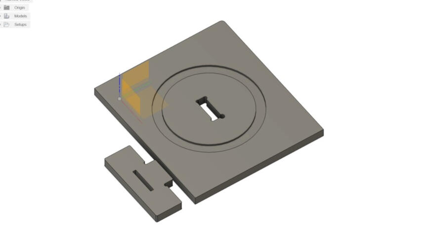 The test components include a plate designed for 2D carving (a concentric circle to assess
carving precision), a rectangular hole is
incorporated to conduct fitting tests with various types of dog bones, and an outcut. A
corresponding piece is provided
to insert into the hole, facilitating an examination of the fit. This piece additionally,
includes a line in the middle to test drilling.
The test components include a plate designed for 2D carving (a concentric circle to assess
carving precision), a rectangular hole is
incorporated to conduct fitting tests with various types of dog bones, and an outcut. A
corresponding piece is provided
to insert into the hole, facilitating an examination of the fit. This piece additionally,
includes a line in the middle to test drilling.
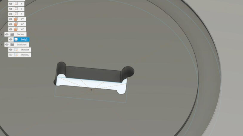
Depending on individual preferences and design constraints, various types of dogbones
can be incorporated. These considerations are particularly crucial, as CNC machines are
unable to cut angles under 180°. IT is crucial to consider the tool diameter in the design
of the dog bones as the dog bone diameter should be equal are more than the tool diameter.
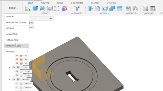 The next step is to switch the workspace to "Manufacturing".
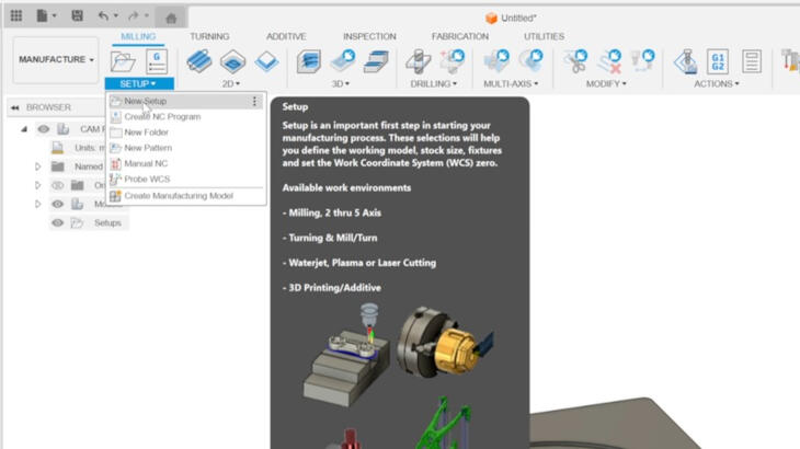
A new setup has to be created.
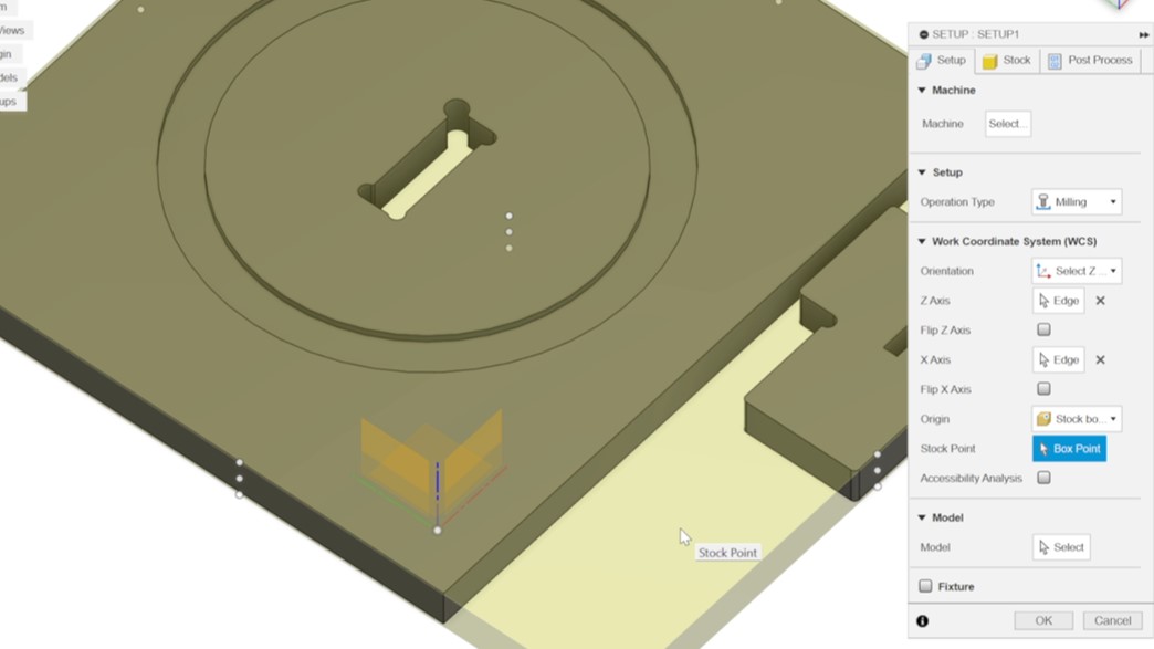 In the setup process, you have the option to select a machine from the library, provided it is
available. Additionally, it is
recommended to set the origin at one of the edges of the stock and place it at the bottom of the
design for optimal
results. Alternatively, you can choose specific models to include in the manufacturing process.
By default, all bodies are
In the setup process, you have the option to select a machine from the library, provided it is
available. Additionally, it is
recommended to set the origin at one of the edges of the stock and place it at the bottom of the
design for optimal
results. Alternatively, you can choose specific models to include in the manufacturing process.
By default, all bodies are
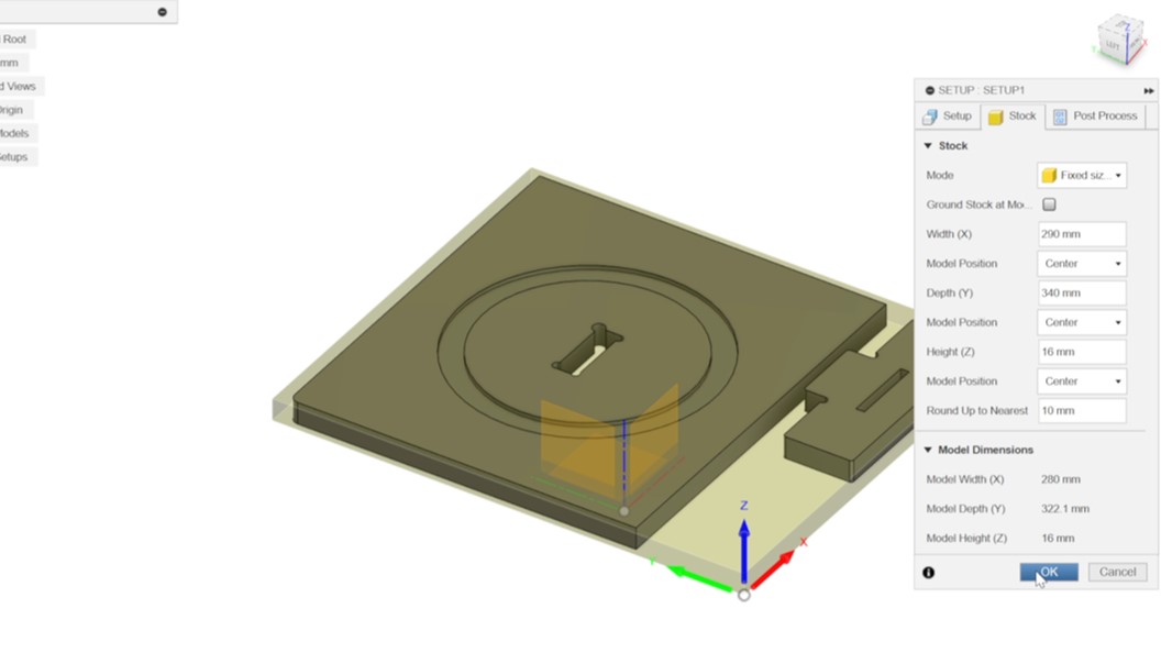
Go to the tab "Stock". In default the mode is "relative size box", change it to "absolute
size box" and set the
preferred values. Height should be the material thickness. After that, you can click on
"OK".
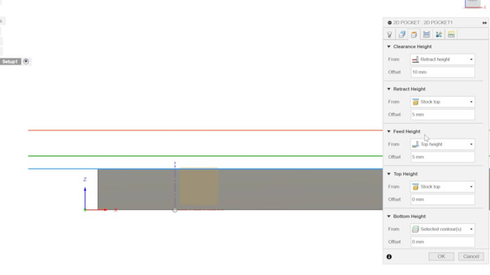
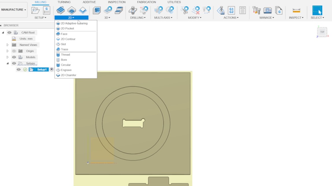 ThClick on "2D" and choose "2D Pocket", which will open a window on the right side.
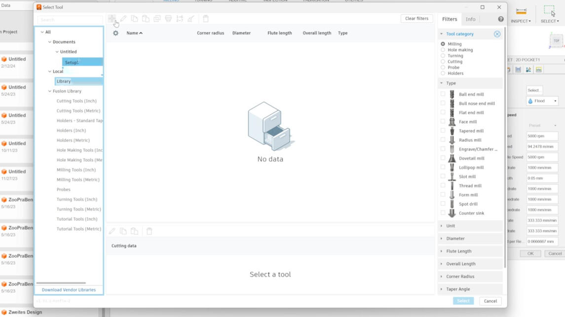
Click on "Select" next to the tool. A window occurs. Click on "Library" and the "plus
symbol" in the right upper corner of the window.
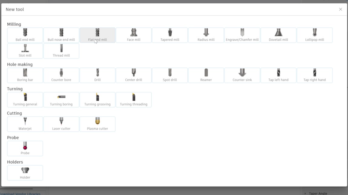 You can choose a tool profile. We used the "Flat end mill" profile.
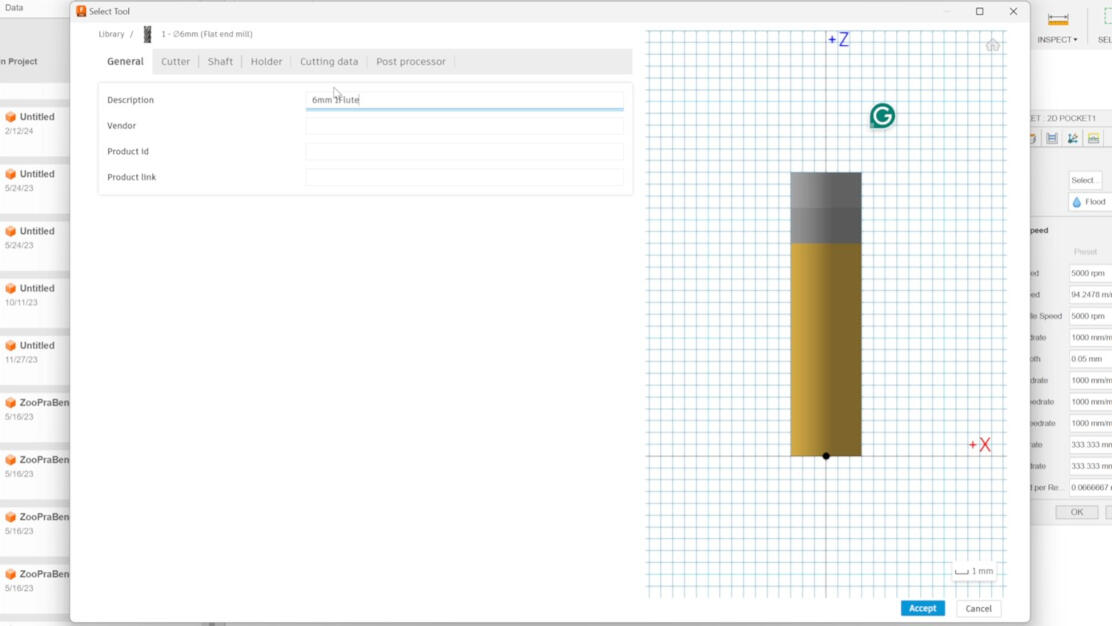
Next step is to describe the tool in a way you are able to identify the tool easily. A good
way is to start with the diameter, then the flute, and the type of material to cut.
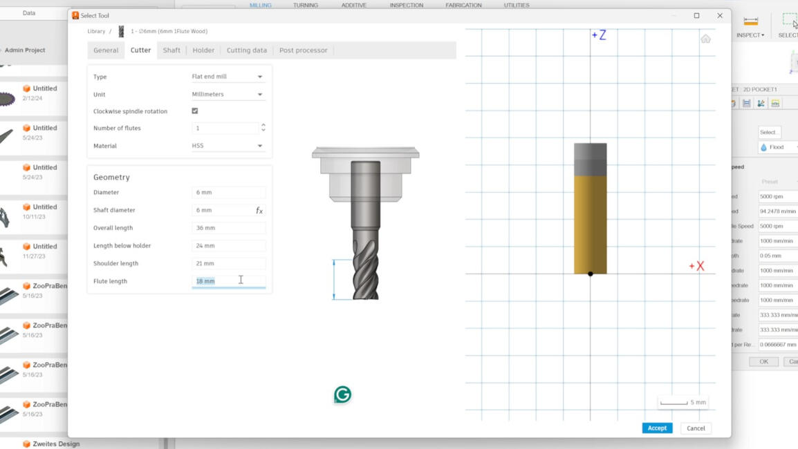 Go to "Cutter" tab. Here you can specify the parameters of the milling tool and tool holder. We
used the parameters shown in the picture.
Go to "Cutter" tab. Here you can specify the parameters of the milling tool and tool holder. We
used the parameters shown in the picture.
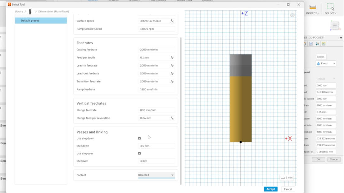
Go to the tab "Cutting data". Here you can enter the rpm, the feeding rate, etc. We used the
parameters shown in the picture. After that, click on "Accept".
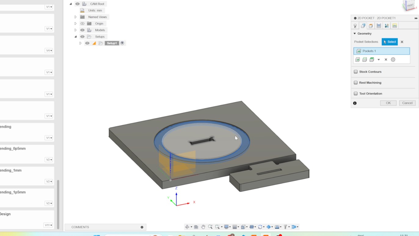 Go to the tab "Geometry" Tab and click on the face you want to create a pocket out of.
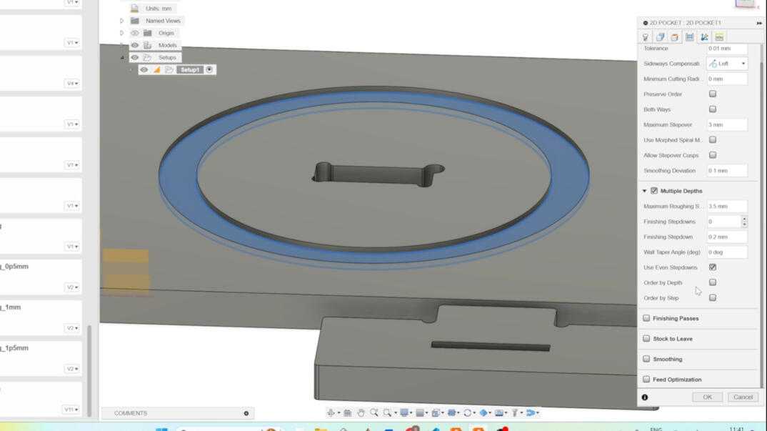
Navigate to the 'Passes' tab and adjust the tolerance as needed. Enable 'Multiple Depths'
and customize the parameters
according to your preferences. Reducing the step-down can enhance the cut
quality and extend the tool's lifespan. After choosing the right parameters for your cut,
you click on "OK".
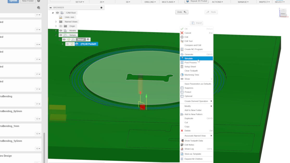 To check, if the cut works out in theory, you can open the Simulation by going "right click" to
"Simulation".
To check, if the cut works out in theory, you can open the Simulation by going "right click" to
"Simulation".
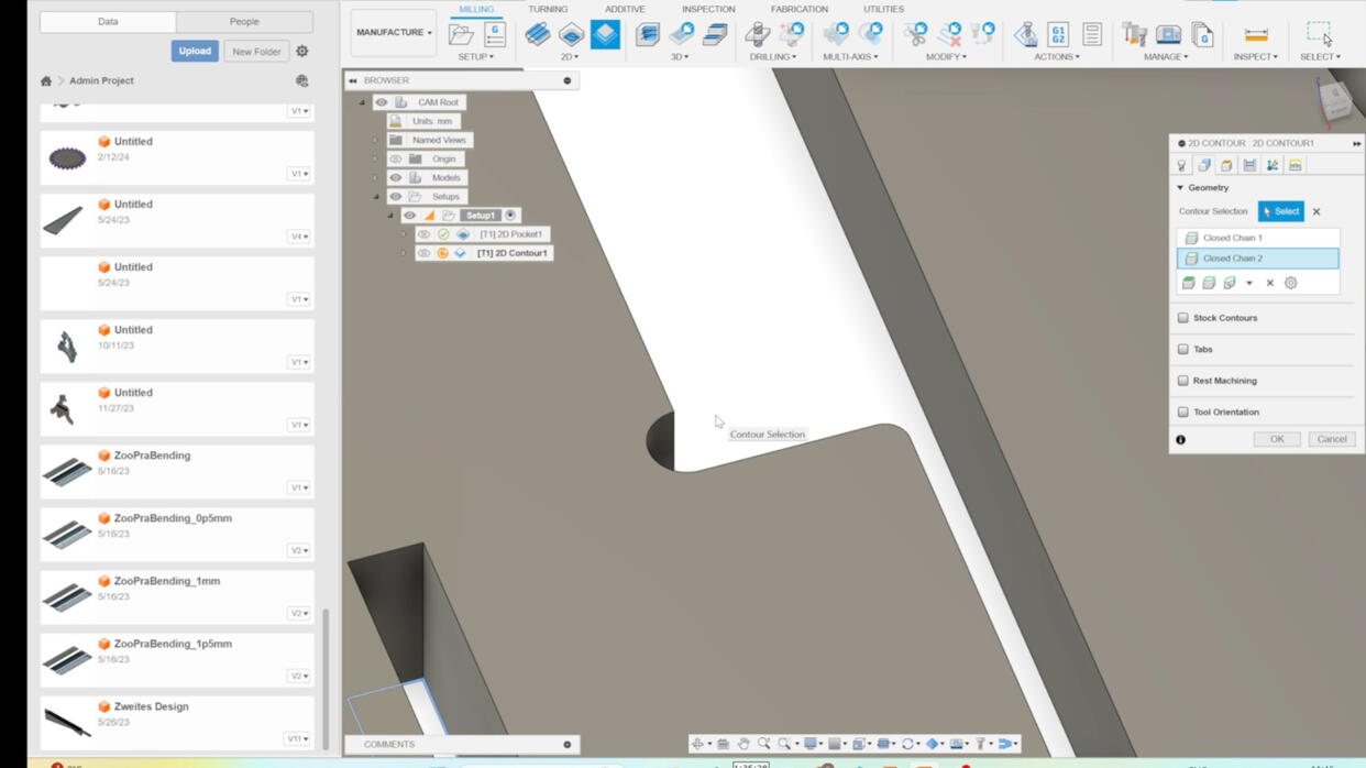
The next step was to create th cut through that are no cutouts of a whole object. To start
you go to "2D" and click on "2D Contour".
Choose the faces you want to contour. I just created a contour that has the width of the
tool to test runout.
 Navigate to the "Heights" tab and select "Bottom Height." Set the distance as "relative to
contour" to -0.1 mm to ensure a precise cutout
Navigate to the "Heights" tab and select "Bottom Height." Set the distance as "relative to
contour" to -0.1 mm to ensure a precise cutout

Check if "Multiple Depths" is activated and then click on "OK".
 After that you can duplicate the last created setup by "right click" on it and select
"duplicate".
After that you can duplicate the last created setup by "right click" on it and select
"duplicate".

Open the duplicated job and choose a different contours for the final cutout.
 Activate tabs to secure the workpiece. Design the tabs so that they are strategically placed
along the contour,
avoiding corners. If needed, manually position them next to straight lines of the contour for
optimal results.
Activate tabs to secure the workpiece. Design the tabs so that they are strategically placed
along the contour,
avoiding corners. If needed, manually position them next to straight lines of the contour for
optimal results.

The final step involves creating a slot to test for runout. Click on '2D' and choose 'Slot.'
Next, select the contour or line of the slot.
Double-check to ensure that 'Multiple Depths' is activated and then click 'OK' to proceed.
 To ensure that each setup adheres to the intended settings, navigate to the simulation tab and
carefully review the tool path for any errors. Furthermore, you have the option to
rearrange the order of setups by simply dragging and dropping them on the right side of the
window for better organization.
To ensure that each setup adheres to the intended settings, navigate to the simulation tab and
carefully review the tool path for any errors. Furthermore, you have the option to
rearrange the order of setups by simply dragging and dropping them on the right side of the
window for better organization.

Once you have verified that the simulation yields the intended outcome, proceed to create
the post-processing file. Simply right-
click on the "Setup" located on the right side of the window and select "Post Processing".
 Click on the "folder" icon next to "post" . In the new window, select "Local", then click on
"Import" at the top. Choose the required file (depending on your machine) and click "Select".
Click on the "folder" icon next to "post" . In the new window, select "Local", then click on
"Import" at the top. Choose the required file (depending on your machine) and click "Select".

Navigate to the output 'folder' icon, choose your desired destination, and then click 'Post'
to create the post precessing file.
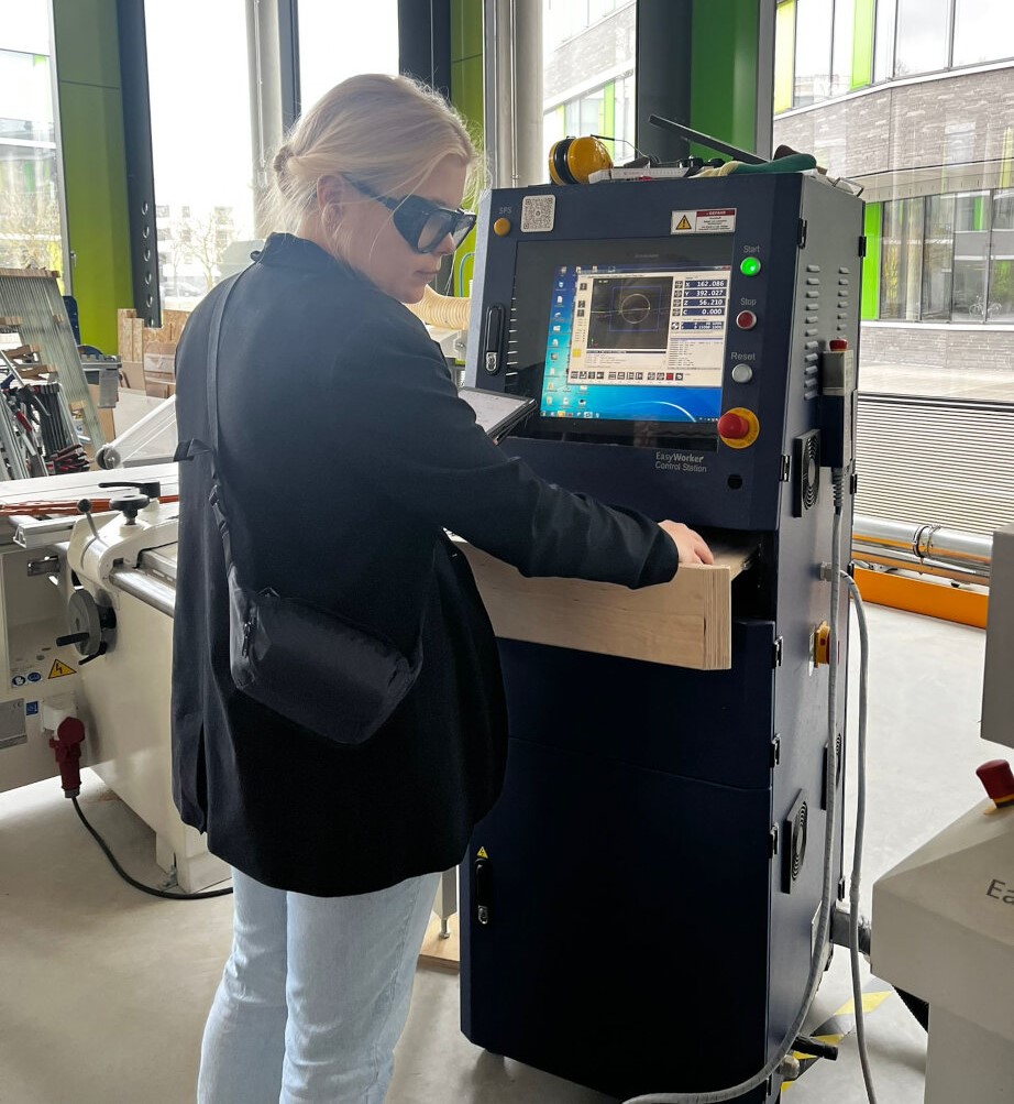
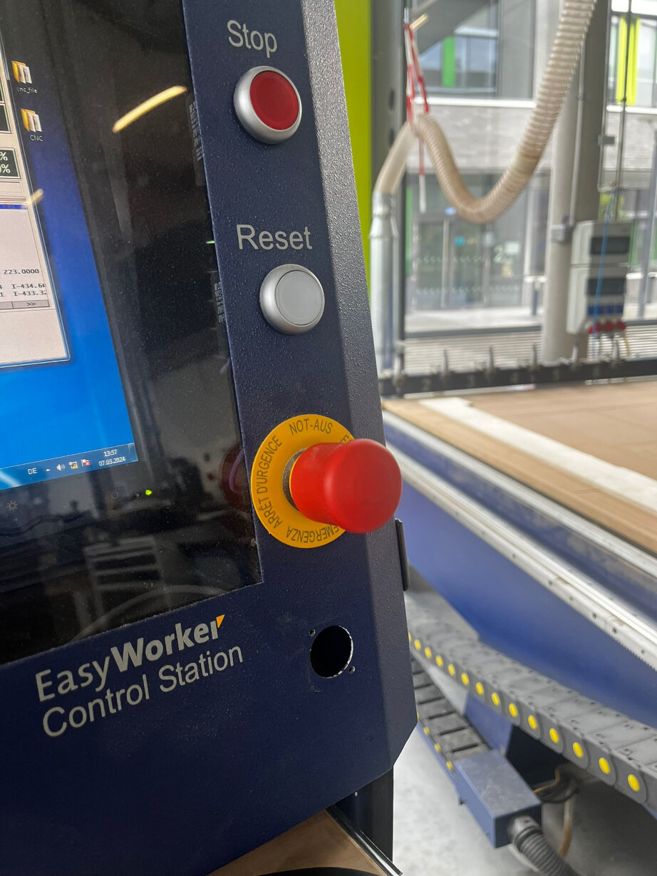
Machine Safety
The CNC machine is a powerful tool that can be dangerous if not used properly.
It is important to follow the safety guidelines to ensure that you and others are safe while using
the machine.
First thing first; If you are alone in the Lab, do not run the CNC.
Before the machine starts;
- To protect our ears from the loud sound of the machine, we should wear either headphones or earplugs.
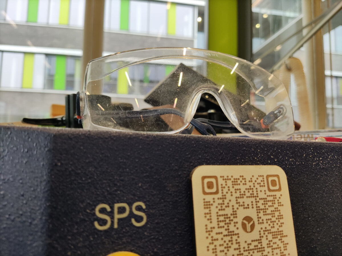
- Glasses must be worn against any harm from the machine.
- Keep the machines and surrounding clear. You can use vacum cleaner for collecting the dust and rest of the wood.
- Be aware place of the fire extinguisher.
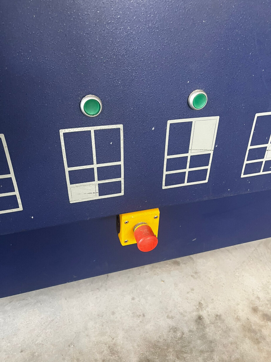
- Be aware where are the safety buttons! There are buttons on the bottom part, on the left side, and the right side of the machine.
While the machine working;
- If you hear any strange voice or see an unexpected situation on the machine, use the safety button to turn off the machine.
- Do not cross the safety band. Set a distance between the machine and you.
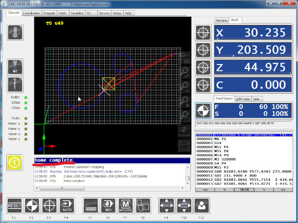
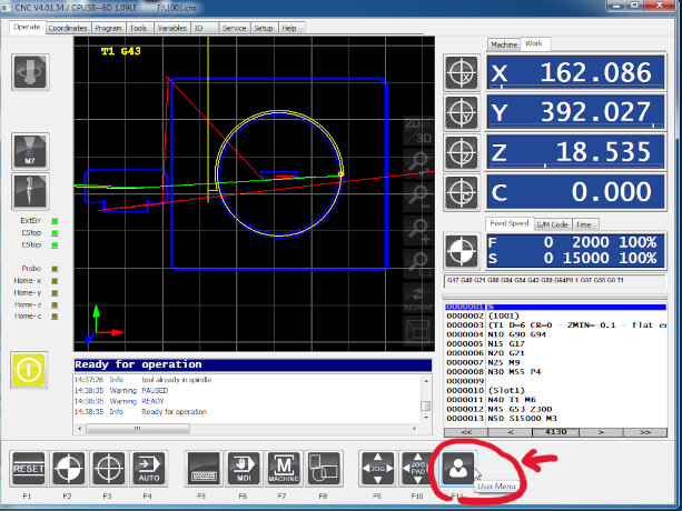
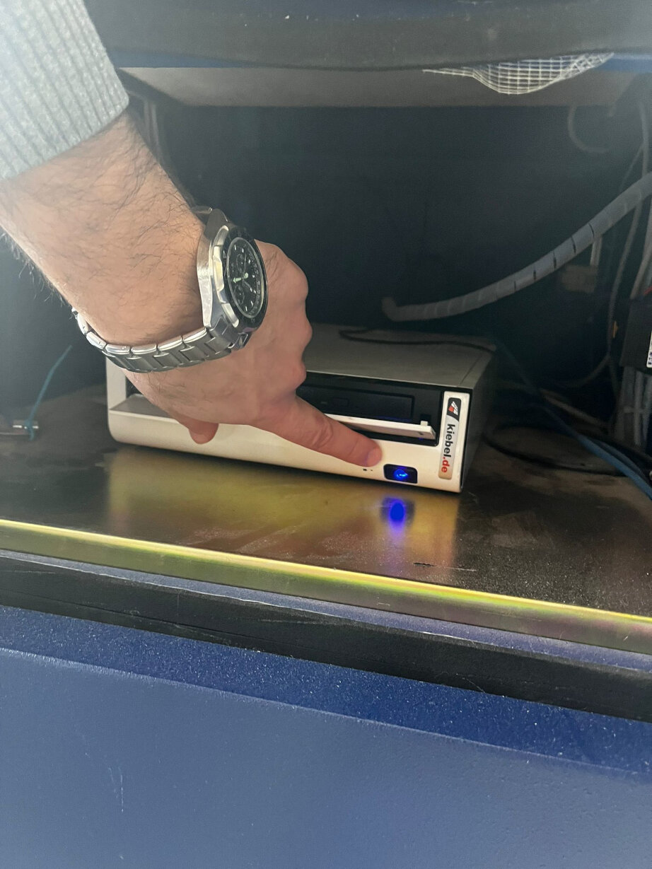
Operating the Machine
- Turn on the high-pressure valve.
- The machine's power is connected, but it is typically locked with a padlock on the main switch.
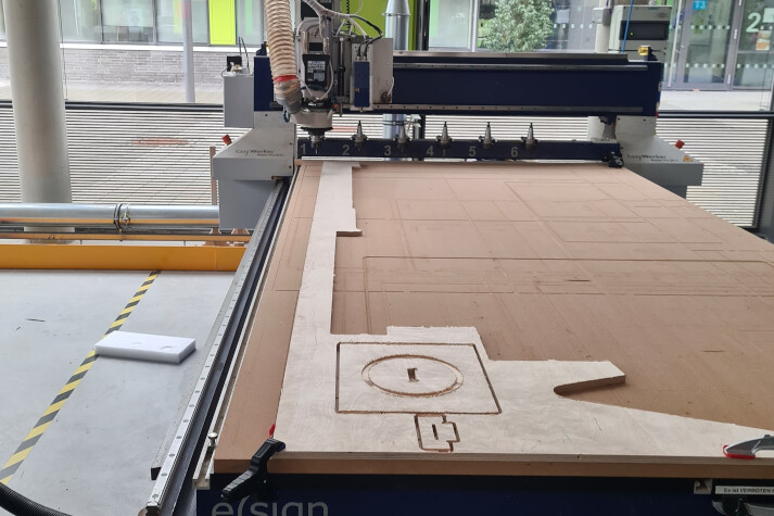
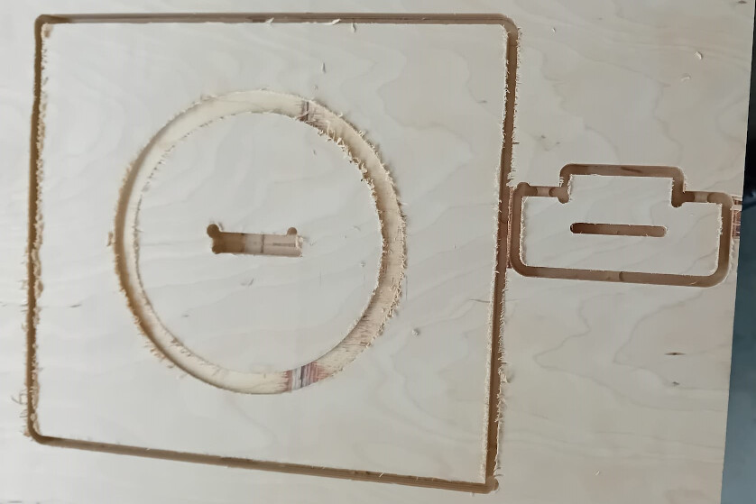
Results
Milling the part did not take long, only about 10 minutes. As we used an upcutting tool, the edges
were
relatively rough. However, a bit of sanding solves this issue.
Milling this part was not only conducted to sow us how we can use the CNC to fabricate parts we
designed but also
to test special parameters for the CNC. These are in principle the
fixturing of the material and
the speeds during cutting and after the milling was completed, the runout, alignment and tolerances
of
finger joint press fits.
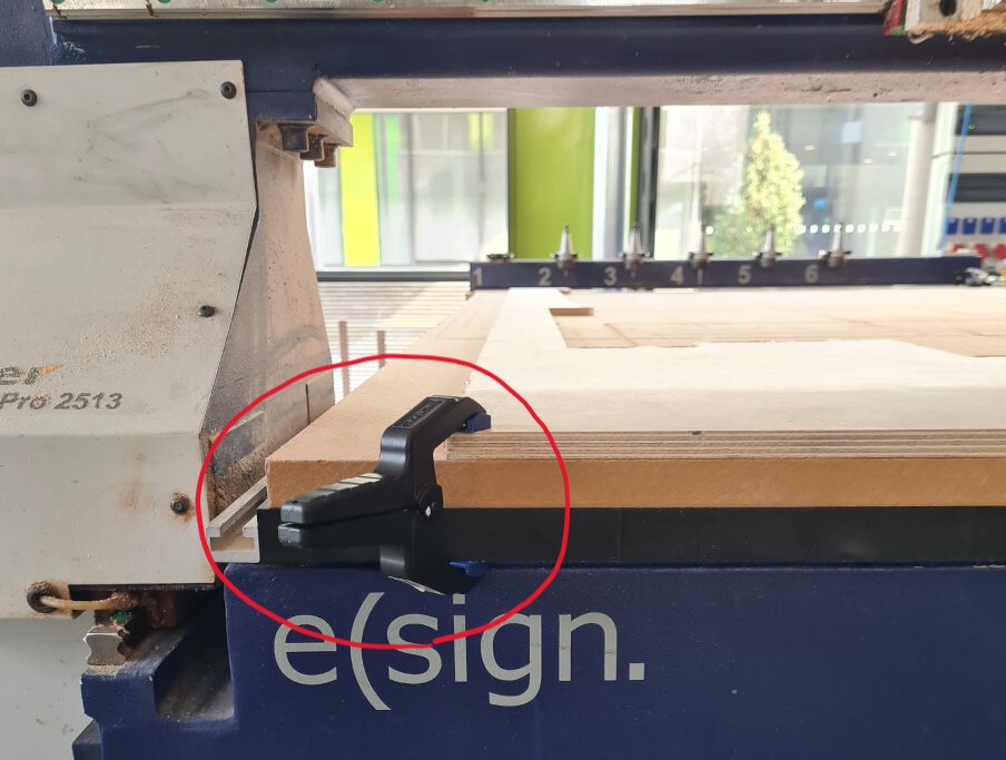
Fixturing
The fixturing was achieved by a vacuum bed with clamps for additional security. The vacuum bed alone
would have been enough for the
part as even hitting the wood slightly from above in an angle did not appear to move it. Of course,
additional clamping is always
recommended.
Spindle Speed
During the milling, we manually decreased the spindle speed from 15000 rpms to 12000 rpms. However,
only
by listening to the machine,
we assessed that lowering the spindle speed is not a good idea. The sound is difficult to describe
but
it could be described
as "ugly". Instead of a purring cat the machine was screaming at the lowered spindle speed.
Therefore,
we increased it
to 20000 rpms which definetly made "happier" sounds.
Runout
The runout is the deviation of the actual cutting width from the diameter of the milling bit. We
tested
this with the pocket on the
smaller part of the test piece. Here, the slot was designed to be 6 mm wide, exactly the width of
the
tool. Therefore, the CAM
generated a toolpath of only one pass such that the milling bit only passed this pocket once. Also
depth-wise the cut was accomplished
in a single pass as the depth of the pocket of 3 mm is less than the stepdown size of 3.5 mm for
this
tool, as we defined in the settings
for the tool in the CAM.
By using a calliper, we measured the width of the pocket to be 6.00 mm. With the precision of the
calliper of 0.05 mm (or plus and minus 0.025 mm) we concluded that the runout is less than 0.025 mm
deviating from 6.00 mm.
Alignment
Testing the alignment means to test whether the axis of the CNC are exactly orthogonal and by this
whether a rectangle in the design is also exactly rectangular in reality when milling it. For this,
we used the two orthogonal sides of the larger
part of the test piece and an "L"-shaped tool called a machinist's square. This tool has two
orthogonal sides which can be
used to investigate if other presumably 90° corners are actually 90° or not. Simply by positioning
it on the corner and looking at it against the
light can show whether the edges deviate from the tool's edges.
In our case, no light was visible between the test piece and the square tool. Therefore we conclude
that the
alignment af the x- and y-axes are prefect.
Joint Tolerances
During CAM for this test piece, we defined the tolerance to be 0.01 mm. This CAM tool however always
subtracts more
material defined by this tolerance. Hence, for a loose fit, the tolerance must be increased. To test
the tolerance
we used, the two parts can simply be joined together - or lets say it can be tried. Sometimes the
fit is too tight
and it cannot be joined. This was actually not the case for us but we did a design mistake. Due to
it, the length
of the slot was shorter (48 mm) than the length of the finger (50 mm).
However, the tolerance can still be tested with the width. Here, we just joined a corner of the
finger instead of the
whole finger with the slot as shown in the image. This fit was quite loose but also not too loose as
the joined pieces
can be lifted up only by touching the smaller piece. A tolerance of 0.01 mm is therefore a good fit.


.jpg)